
International Research Journal of Engineering and Technology (IRJET) e-ISSN: 2395-0056
Volume: 11 Issue: 05 | May 2024 www.irjet.net p-ISSN: 2395-0072
International Research Journal of Engineering and Technology (IRJET) e-ISSN: 2395-0056
Volume: 11 Issue: 05 | May 2024 www.irjet.net p-ISSN: 2395-0072
1Assistant Professor, Department of Electronics & Communication Engineering,Chaitanya College of Engineering, JNTU-GV University, Vishakhapatnam, India
2Assosciate Professor, Department of Electronics & Communication Engineering,Chaitanya College of Engineering, JNTU-GV University, Vishakhapatnam, India
3Assistant Professor, Department of Electronics & Communication Engineering,Chaitanya College of Engineering, JNTU-GV University, Vishakhapatnam, India
4 Professor, Department of Electronics & Communication Engineering, MVGR College of Engineering Autonomous, Vizianagaram, India
Abstract Antennas with these qualities are in high demand these days: they must be compact, low profile, multiband, or broad band. Since communication technologyhasadvancedoverthepast10years,therehas been a rise in the need for wideband, multiband, affordable,andcompactantennas.Thesespecificationscan be met with the use of fractal antenna designs. Patch antennasinthecurrent worldusefractal shapesto obtain hugebandwidthandvariousotherbeneficialproperties.In wireless communication, Ultra-Wideband Patch antennas are in high demand. This paper presents a low profile Sierpinski fractal antenna for wide band applications. The suggested antenna's design increases its impedance band width and radiation efficiency by enclosing Sierpinski Fractals within a 1 mm-wide circular ring. A micro-strip feed line supplies the suggested antenna, which has dimensions of 29 x 28 x 1.6 and a radiation efficiency of 92%.Theantennaoperatesinthefrequencyrangeof2.0to 14.3 GHz. Over the working WB range, the radiation pattern remains constant. High Frequency Structure Simulator (HFSS) is used for the design and simulation of theSierpinskifractalWideband antenna.FR-4Substrateis used for fabrication, and Vector Network Analyzer is used for testing. Ultimately, Wind-Driven Optimization (WDO) wasto beusedinorder tocreatethis proposed Sierpinski FractalWidebandAntenna.
Index Terms Fractal Antenna, Ultra Wide Band (UWB), SierpenskiFractals,WindDrivenOptimization
Using radio transmission, broadband technology usesverylittlepowertosendlargevolumesofdigitaldata over short distances over a wide band width of 7.5 GHz, which varies from 3.1 GHz to 10.6 GHz. It meets the requirements for wireless applications, including highspeed data transfer and short-range radars. For a Wideband antenna to provide excellent impedance matching and generate high gain radiation in the desired direction, a broad operational band width is required.
Many resonances are available with a self-similar fractal antenna The characteristics of fractal WB antennas are low resonance, unidirectional radiation pattern, and wide band phenomena. Fractal Wideband antennas are utilized extensively for ultra wide band applications because of their appealing properties. The narrow band width operationisfirstprovidedbydesigningacircularringwith a width of 1 mm. Radiation is created when fractals are added to antennas, allowing for the existence of unique current distributions. Consequently, the presented fractal antenna willhaveanextremelywideband width.Utilizing Sierpinski Fractals within the circular ring yields an exceptionally broad band. Improved radiation properties arealsoobtainedbyincludingsierpinskifractalswithinthe ring.Thecoreregionofthepatchhasfractalsetchedintoit, which may not have a significant impact on the radiation properties.Morefractalsareincorporatedtoachievegood radiationpropertiesandawidebandwidth.
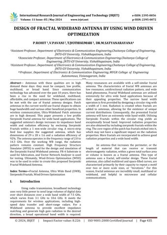
An antenna that increases the perimeter, or the length of material that can receive or transmit electromagneticradiation,withinagiventotalsurfacearea or volume is known as a fractal antenna. This type of antenna uses a fractal, self-similar design. These fractal antennas,alsocalledmultilevelandspace-filledcurves,are characterizedprimarily bytheircapacitytorepeata motif over two or more scale sizes, or "iterations." For this reason,fractalantennasareincrediblysmall,multibandor wideband, and helpful in microwave and cellular communications.
International Research Journal of Engineering and Technology (IRJET) e-ISSN: 2395-0056
Volume: 11 Issue: 05 | May 2024 www.irjet.net p-ISSN: 2395-0072
Oneeffectiveexampleofafractalantennausedas aspacefillercurveisashrunkenfractalhelix.Inthiscase, a copper line is merely a small fraction of a wavelength. Because fractal antennas can operate at multiple separate frequencies simultaneously with good to exceptional performance, their response differs greatly from that of traditional antenna designs. Because standard antennas must be "cut" for a certain frequency, they are typically only effective at that frequency. The fractal antenna is therefore a great design for multiband and wideband applications. Furthermore, the antenna's fractal nature reduces its size without the need for any external parts, suchascapacitorsorinductors.
Based on wind movement in the surrounding environment, Wind Driven Optimization (WDO) is a revolutionary bio-inspired global optimization technique. This method's initial concept, which entailed simulating wind flowing from high pressure zones to low pressure areas, was developed by Z. Bayraktar. It mimics the travel of a group of tiny air packets following Newton's second lawofmotionthroughoutasearchspace.Themovementof airthroughtheearth'satmosphereiscomparabletothis.It is comparable to the optimization process, in which moving from poorly performing to good performing combinations within a search area is the aim. When comparedtootherparticle-basedmethods,WDOisrobust and provides more process optimization degrees of freedom. The WDO method has also been used to the electromagnetic field. It has been used to design dual resonance,highgainmicrostripfractalantennas.
The proposed Sierpenski Fractal Wide-band antenna is created on a FR4 substrate with a relative permittivity of 4.4 and a thickness of 1.6 mm (h). Circular
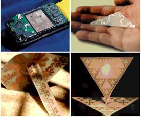
patch antenna with a resonance frequency of 6 GHz is intended for wideband applications due to its appealing radiation properties. Equation (1) is used to compute the circularpath'sradius.
Theradiusofthepatchis r,thespeedoflightis c, andtheresonancefrequencyis fr
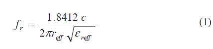
Thecircularpatch'sradiusof8.5mmcanbefound using equation (1).The micro-strip feed line with an impedance of 50 ohms feeds the circular patch antenna. Eqn(2)isusedtocalculatethemicro-stripfeedlinewidth.
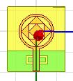
Thewidth(w)ofthemicro-stripfeedline,whichis 3 mm, may be found using equation (2). As a result, by etching a circle patch with a radius of 7.5 mm from a circularpatchwithan8.5mmradius,acircularringwitha width of 1 mm is created. In order to enhance radiation propertiesandbandwidth,Theintroductionofthreeorder SierpinskiFractalsinsidethecircularringisdemonstrated in Figure 2. The first order Sierpinski Fractal measures 10.6mm,thesecondordermeasures7.6mm,andthethird order measures 4.5 mm. The substrate is fed through a micro-strip feed line that measures 11.1 x 3 mm2, and is situated beneath a partial ground plane with length and width(LgxWg)of10x28mm2.
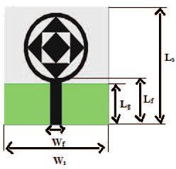
2: ThegeometryofSierpenskiFractalAntenna design
International Research Journal of Engineering and Technology (IRJET) e-ISSN: 2395-0056
Volume: 11 Issue: 05 | May 2024 www.irjet.net p-ISSN: 2395-0072
a) Simulation Using HFSS: HFSS (High-Frequency Simulation Software) version 13.0 is used to model and analyze the aforementioned antenna design, as illustrated in Fig. 3 below.
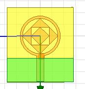
IV. Simulation Results of Sierpenski Fractal Antenna using HFSS
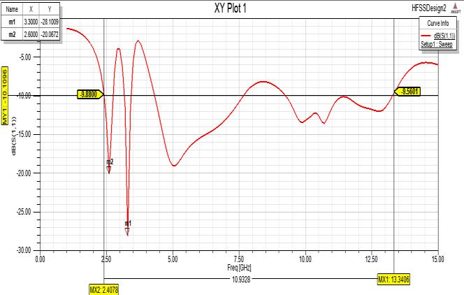
a) S11
Figure 4 displays the S11 for the Sierpinski Fractal antenna that corresponds to Figure 3. This chart shows that the 10.93GHz band width, which is between 2.4GHz and 13.34GHz, has a return loss of -28 at 3.3GHz andfallsbelow-10dB.
b) VSWR
A perfect match requires a VSWR of at least unity. picture 5 displays the VSWR of the Sierpenski Fractal Antenna with an integrated HFSS, which correspondstopicture3.Anantenna'sVSWR rangesfrom 1toinfinity.Inreal-worldapplications,itoughttobeinthe range of 0 and 2. This graph shows that the appropriate bandwidthislessthan-10dBandthattheVSWRat3.3GHz is1.08.
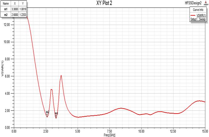
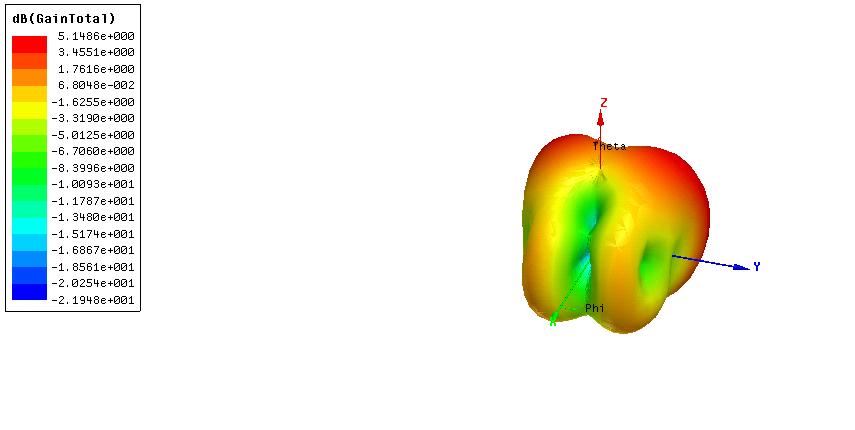
Figure 5:VSWRofSierpenskiFractalAntenna c) Gain
The power transmitted per unit solid angle is all thatconstitutesgain.The3-DgainoftheSierpenskiFractal Antenna integrated into the HFSS is shown in Figure 6 in comparisonto Figure3. Anyantenna hasa gainof greater than 3dB for all uses. This antenna has been observed to havea5.14dBgain.
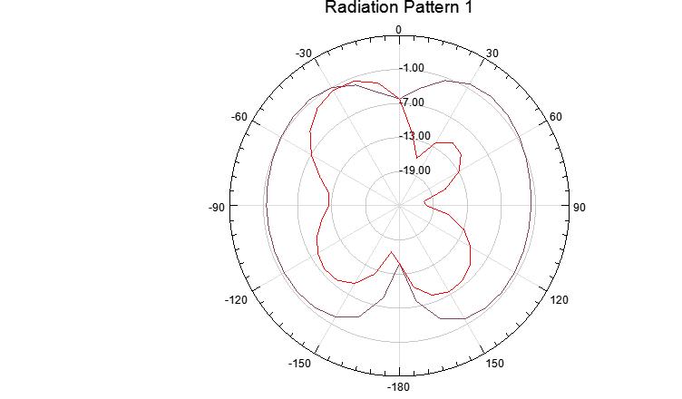
d) Radiation Pattern
A radiation pattern is the fluctuation in power of an antenna with respect to direction away from the antenna.Thispowerchangeasafunctionofarrivalangleis observedintheantenna'sfarfield.Theradiationpatternof theSierpenskiFractalAntennaisshowninFigure7,which correlatestoFigure3andplotsgainagainstthetaandphi.
International Research Journal of Engineering and Technology (IRJET) e-ISSN: 2395-0056
Volume: 11 Issue: 05 | May 2024 www.irjet.net p-ISSN: 2395-0072
V. Fabrication Model of Proposed Antenna

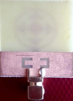
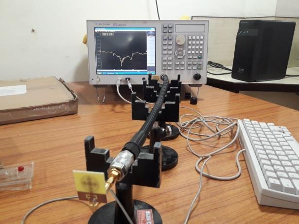
The graphic depiction below compares the theoreticallyachievedresultsfromtheconstructedmodel, such as return loss and VSWR of the Sierpenski Fractal Antenna,withthesimulatedresultsoftheplannedantenna inHFSS(High-frequencySimulationSoftware).
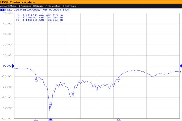
a) S11
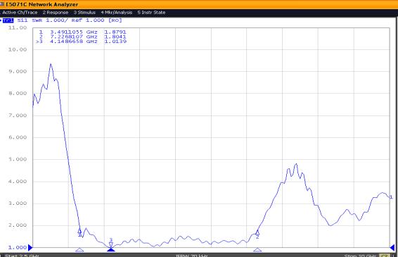
b)VSWR
International Research Journal of Engineering and Technology (IRJET) e-ISSN: 2395-0056
Volume: 11 Issue: 05 | May 2024 www.irjet.net p-ISSN: 2395-0072
II) Comparison Results
c) S11
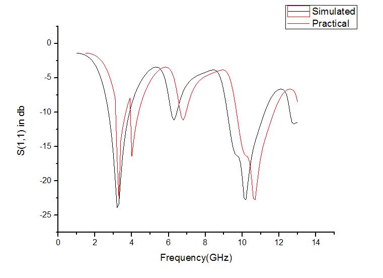
12: ComparisonofS11
d) VSWR
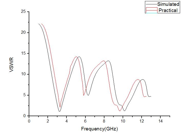
Figure 13: ComparisonofVSWR
Using a network analyzer, the Sierpenski Fractal Antenna's practical results are achieved, and the parametersofreturnlossandVSWRarechecked.
V RESULT ANALYSIS
*ProposedWork
The reference papers compare return loss, VSWR, and antenna gain in relation to fractal antennas for wideband applications and above result analysis. When comparing the suggested work's antenna gain to Fractal Antennas,whichservedasthemodel,itishigher.
Due to the device's restricted area, nearly all contemporarywirelesscommunicationdevicesrequirethe integration of multiple wireless communication protocols into a single unit Multi-band antennas are therefore desperately needed for WLAN, Wi-Pro, Bluetooth, PCS/LTE, WiMaX, UWB, and US Public Safety Band applications.Thisisbecausetheseantennascanbeusedin nearly all commercial communication devices, including medical devices, tablets, smart phones, portable laptops, digital cameras, and medical equipment. The proposed 10.6 GHz Sierpinski Fractal Wideband Antenna has a radiation efficiency of 92% and a bandwidth that spans from 2.0 GHz to 14.3 GHz. The volume of the suggested antennaisrathersmall,measuringonly29x28x1.6mm3, in contrast to other fractal antennas that are currently in use. You can add more sierpinski fractals to improve radiationefficiencyandbandwidth
[1] S. Suganthi, S. Raghavan, D. Kumar and S. H. Thilagar, "Planar fractal antennas for wireless devices,"2011 3rd International Conference on Electronics Computer Technology, Kanyakumari,India,2011,pp.98-102,doi: 10.1109/ICECTECH.2011.5941568.
[2] M. R. Jena, B. B. Mangaraj, and R. Pathak, “A Novel Sierpinski Carpet Fractal Antenna with Improved Performances” American Journal of Electrical and Electronic Engineering, Vol. 2, Issue 3, pp. 62-66, January2014
[3] M.R.Jena,G.P.MishraandB.B.Mangaraj,"Microstrip Patch Antenna Design Using Fractal Slot Geometries for Multiband &; Wideband Applications,"2018 International Conference on Recent Innovations in Electrical, Electronics & Communication Engineering (ICRIEECE), Bhubaneswar, India, 2018, pp. 485-488, doi:10.1109/ICRIEECE44171.2018.9008457.
[4] M. Tarbouch, A. El Amri, H. Terchoune and O. Barrou, "A compact microstrip patch antenna based on fractal geometry on the ground plane,"2018 International ConferenceonAdvancedCommunicationTechnologies and Networking (CommNet), Marrakech, Morocco, 2018,pp.1-8,doi:10.1109/COMMNET.2018.8360245.
International Research Journal of Engineering and Technology (IRJET) e-ISSN: 2395-0056
Volume: 11 Issue: 05 | May 2024 www.irjet.net p-ISSN: 2395-0072
[5] M.F.Mosleh,S.A.ShandalandN.A.Salam,"Wideband Fractal Circular-Shaped Microstrip Patch Antenna for Recent Wireless Applications,"2019 2nd International Conference on Electrical, Communication, Computer, Power and Control Engineering (ICECCPCE), Mosul, Iraq, 2019, pp. 56-61, doi: 10.1109 / ICECCPCE46549.2019.203748.
[6] P.GianvittarioJohnandYahyaRahmat Samil,"Fractal Antennas:ANovel Antenna Miniaturization Technique and Applications ",IEEE Antennas and Propagation Magazine, vol.44,no.1,pp.20-36,2002.
[7] CarlesPuente-Baliarda etal.,"Onthe behaviourofthe Sierpinski Multiband Fractal Antenna",IEEE TransactionsonAntennasandPropagation, vol.46,no. 4,pp.517-523,1998.
[8] Rowdra Ghatak et al., "Perturbed Sierpinkski Carpet Antenna with CPW feed for IEEE 802.11 a/b WLAN Application",IEEE antennas and Wireless Propagation Letters,vol.7,pp.742-744,2008.
[9] Yukio Iida et al., "One-dimensional Fractal Broadband Antenna for Demand Expansion in RFID Systems",IEEE,pp.3221-3224,2007.
[10] LiuYing etal.,"MicrostripFractal patchantenna for Multi-Band Communication",IEEE 23rd International Conference on Microwave and Millimeter Wave TechnologyProceedings,pp.600-602,2002.
[11] NoorAsinizaMuradetal.,"FractalPatchAntennafor GPS Application",IEEE Student Conference on Research and Development Proceedings, pp. 102-104, 2003.
[12] Gagandeep Kaur, Chahat Jain and Munish Rattan, "A novel multiband Psi (Ψ) slotted fractal antenna for Sband applications",2016 International Conference on Computing Communication and Automation (ICCCA), 2016.
[13] S. Akkole and N. Vasudevan, "Compact Multiband Microstrip Fractal Antenna Design for Wireless Applications –An Overview," 2020 4th International Conference on Electronics, Communication and Aerospace Technology (ICECA), Coimbatore, India, 2020, pp. 554-558, doi: 10.1109 / ICECA49313.2020.9297629.