
International Research Journal of Engineering and Technology (IRJET) e-ISSN: 2395-0056
Volume: 11 Issue: 05 | May 2024 www.irjet.net p-ISSN: 2395-0072
International Research Journal of Engineering and Technology (IRJET) e-ISSN: 2395-0056
Volume: 11 Issue: 05 | May 2024 www.irjet.net p-ISSN: 2395-0072
Shreyash Patil1 , Vaishnavi Thakre2 , Deven Marathe3 , Shreyas Shankarshete4
1234 UG Students, Dept. of Mechanical Engineering, D. Y. Patil College of Engineering, Maharashtra, India
Abstract - Belt conveyors are one of the most commonly used equipment for transporting bulk materials in various industries. They are versatile, efficient, and reliable, making them suitable for a wide range of applications. Optimizing the current Belt Conveyor System was the goal and purpose of our project. We applied analytical and numerical methods to this. A key factor in reaching the goals was the process used to choose the best material. The dimension constraints for this project, as well as economic considerations, are taken into account in all processes and activities. We attempted to guide our approach in light of India's expanding industrial sector and deliver the best possible solution.
Key Words: Optimizing, Dimension constraints, Economic considerations
Large volumes of coal can be handled effectively by belt conveyors used in coal applications. The type of coal, the amounttobeconveyed,thedistancetobetravelled,andthe terrainoftheroutearesomeofthevariablesthataffectthe conveyorsystem'sdesign.Abelt,pulleys,idlers,andadrive systemmakeupabeltconveyorsystem. Sinceitbearsthe weight and supplies the required traction, the belt is the mostimportantpartoftheconveyorsystem.Thesizeand weightofthecoalthatneedstobetransporteddetermine thekindandwidthofthebelt.Thebeltissupported,guided, andkeptinalignmentbythepulleysandidlers.Therequired powerissuppliedbythedrivesystem.
1.1 Following are some of the key components of a belt feeder conveyor system
Frame: Theconveyorbeltandotherpartsaresupported bytheframe.Theframeservesasthefoundationforthe system'scontinuousandeffectiveoperation,preventing anyvibrationfromenteringthesystem.
Conveyorbelt:Thepartthatactuallymovesthematerial istheconveyorbelt.Itisusuallyconstructedofsynthetic or rubber material andis intended to endure material deteriorationduringtransportation.
Idlers: Idlersarerollersthatsupportandmaintainthe smoothmotionoftheconveyorbelt.
Drive system: Theconveyorbeltismovedbythedrive system's power. Pulleys, a gearbox, and a motor are usuallyitscomponents.
VariousTypesofresearchstudiesbydifferentauthorsare:
Devendra Kumar et al., reviewbeltconveyormodifications forvariousindustries,highlightingtheimportanceofdesign modifications and safety measures to reduce failures, maintenancecosts,and equipment-relatedaccidents. They discuss the latest technologies and methodologies used in these applications, covering coal mines, cement, and food industries[1]
Chudasama Pratik Naresh etal.,discusstheoptimizationof belt conveyor systems for coal applications, focusing on reducing vibrations, increasing fatigue cycles, minimizing weight, and reducing drive shaft deflection. It details the design, analysis, and optimization procedures, including simulationsandreferencestorelevantresearchstudies[2].
Sayali Todkar et al., discussthedesignprocedureofathreerollertypebeltconveyorsystemforheavydutyapplicationin thecoalprocessingindustry.Thepaperprovidesadetailed studyofthedesigncalculations,stressesonpulleyduetobelt tensions at head side, tail/take up and snub side, and experimentationcarriedouttoverifytheselectedspeedon variousloadconditions[3].
Ankit Gupta et al.,presentsadetailedstudyonthefailure analysisofthebeltintheconveyorsystemforcoalhandling in thermal power plants. The study analyzes the technical characteristicscausingdeviationinthebeltandtheoperating characteristicsofrelevantmachinerycausingdeviation.The authors propose various methods to reduce failure due to deviationduringuse. Overall,thispaperprovidesvaluable insights into the factors causing belt failure and proposes practicalsolutionstoimprovethelifeofthebeltandreduce rackwear[4].
A.W. Roberts et al., describedcomprehensiveguideonthe design and application of feeders for bulk solids handling. The paper reviews the overall requirements for designing gravity flow feeding systems for bulk solids handling with particularemphasisonthefeedingoperationsinassociation withbeltconveying[5].
International Research Journal of Engineering and Technology (IRJET) e-ISSN: 2395-0056
Volume: 11 Issue: 05 | May 2024 www.irjet.net p-ISSN: 2395-0072
Todevelopabeltconveyorsystembyusingsuitablematerial. The newly designed conveyor should have capacity to transport 150 TPH (Tons per hour) of crushed coal and shouldcostlesstomanufacture.
The first step in the design process for our project is identifying any flaws in the current design so that adjustmentsmaybemade.Theproject'sstagesarefinishedin theordershownbelow.
4.1 Identification of needs
We have to reduce the weight of the shaft assembly and lessenthevibrationsintheframeinordertocomplywiththe specifications.Todothis,wefirstlookatthecurrentdesign, thenweruncalculationstochangetheshaftandframedesign andcomponentanalysistochangethematerialoftheshaft andchassis.
4.2 Material Selection
Thematerialselectionconsistsoffollowingsteps:
4.2.1 Screening
1.Function:tosupportmaterialload.
2.Objective:toreducetheweightbyincreasingthefatigue strength.
3.Variable:Material.
4.Constraint:Lengthofshaft.Force.
4.2.2 Property chart
WiththehelpofFunctionandObjectiveswe consideredtheASHBYStandardpropertyChart,Young’s ModulusvsDensityChart.
Plottingtheguidelines:Young’sModulus-100to250GPa, Density-7to8Mg/m3
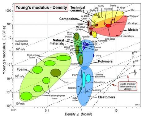
Fig -1:ASHBYStandard property Chart,Young’s ModulusvsDensityChart
Table -1: Potentialcandidatesforframe
4.2.3 Final material selection
After selecting the candidate materials, we calculate the performance index of each material by digital logic method and the material with highest performance index is selected.
Here, Carbon steel, AISI 1141 with performance index 99.65 isselectedfortheframe.
Similarly, Stainless steel, austenitic, AISI 202 with performanceindex 97.31 isselectedfortheroller.
Westartbyfiguringouthowbigthebeltconveyorhastobe. Next,wecalculatetheoverallforcesactingonthedifferent components of the drag chain conveyor as well as the tensions acting on the tight and slack sides of the belt conveyor.Wecalculatetheactualcapacityoftheconveyor andfinallythemotorpowerrequiredtorunoursystemis ascertained
International Research Journal of Engineering and Technology (IRJET) e-ISSN: 2395-0056
Volume: 11 Issue: 05 | May 2024 www.irjet.net p-ISSN: 2395-0072
The conveyor capacity should satisfy the load carrying capacitywithminimalamountofenergyusage.Theconveyor motor's power must overcome the difference between the tightandslacksidetensions.
InputData
C=Conveyorlengthfactor
F = Conveyor coefficient friction factor as per the followingdata
(i) 0.02foreasyconditionforconveying
(ii) 0.024forlesseasyconditionforconveying
(iii) 0.03fordifferentconditionforconveying
Lh=Lengthinmeterhorizontallength (28m)
H=Conveyorlifti.e.(headpulleylevel +tail pulley level)
Hm=Conveyormateriallift(inmm)(20mm)
Mm=Materialmass(kg/m)
Mt=Beltmass(kg/m)ofbeltlength
Mc=Carryingidlerrotatingmassofconveyor(kg/m) (21.78kg/set)
Mi=Returnidlerrotatingmassofconveyor(kg/m)
Uoc=0.4
Ce=0.4for30degreethroughidler
0.434for35degreethroughidler
0.5for45degreethroughidler
o=Conveyoraverageinclination
i.eo=tan^-1(H/Lh)
LITc=Conveyorlengthwhichhastiltedsiderollers
(IfConveyorlengthfortiltsiderollerisnotmentioned takeLITc=Lh)
OmegaWc=2Degree
Dynamicu2=0.5(Friction,rollerandshaft)
I=Material; m^3/sec
Y=bulkdensitykg/m^3
v=beltspeedm/sec
b1=0.666xbeltwidth
g=gravity9.81
Lsk=3meter
Mm=designcapacity/(3.6xV)
Crosssectionalareaofthebelt=0.0678m^2
Total cross sectional area on = 0.0678 x 0.91 =0.55528m^2
Maximum possible capacity for 1000mm belt
i.e.crosssectionalareax3.2x3600x(1000/1000) =60.769>60mtph
Availablecrosssectionalarea=0.111xareareduction factorxbeltfillingfactor
=0.111x0.91x0.9 = 0.090909m^2
Capacity of conveyor
Capacityat1mps=crosssec area x(1.0x3600)x( width–1000)
=0.090909x1.0x3600x(1000/1000) =327.27mtph
5.2 Speed required for 600 mtph
=1.0m/s x(600/327.27)
=1.833(theoretical)
=1.924(5%increased)
=1.924m/s
Thusthedesignspeedislessthantheallowablespeed i.e.3.65mps
Henceitissafeforworkingcondition.
Powercalculationfordriveshaft = PxV/1000 =(15026.383x2.023)/1000 =30.3983KW
Poweratmotorshaft =Poweratdrivepulleyshaft/Driveefficiency =30.3983/0.9
=33.775KW
=40KW
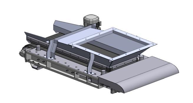
Thewholerepresentationofthesystemorproductutilizing both graphical and non-graphical data is referred to as modeling. Geometric modeling is another word for it. In a computerdatabase,itproducesamathematicaldescriptionof the product or system's geometry and nongeometry in addition to a graphical representation of it. Through modeling,adesignercancreateagraphicaldepictionofan objectonacomputerscreen.
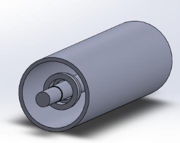
We created a 3D model of the components using SOLIDWORKSdesignsoftware,providinganaccurateviewof eachpart.Modifyingtheproject'sfeaturesduringthedesign phase is easier and reduces the risk of post-completion losses. The base frame, shaft, drive mechanism, belt, and rollerweremodeledaccordingtospecificrequirementsand calculations. Once the components were completed, we assembledthebeltconveyor.
International Research Journal of Engineering and Technology (IRJET) e-ISSN: 2395-0056
Volume: 11 Issue: 05 | May 2024 www.irjet.net p-ISSN: 2395-0072
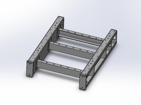
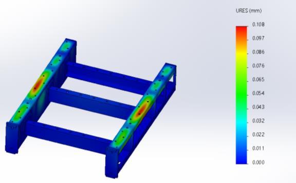
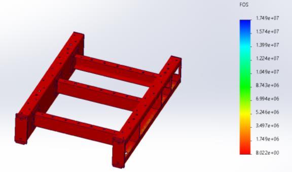
Afterthecompletionofthe3DCADmodel,weanalysedthe part of the product that they should meet to the basic parameter’s which will validate the product configuration whicharestressdistribution,deformation,factorofsafety. Most of the power and torque is been transmitted by the rollershaftso,bothstaticanddynamicanalysisisdoneonit. Alongwiththatweanalysedthestaticloadcarryingcapacity ofthebaseframe.Driveshaftsneedtobestrongenoughto bear the pressure without gaining weight since they are pronetostressesandtorsion.Iftheydo,morematerialwill be consumed, increasingthecost,and more power will be neededduetotheincreasedinertia.
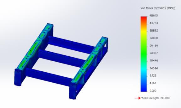
Sr No. Parameter Result
1. YieldStress 390Mpa
2. StaticDisplacement 0108mm
3. Factorofsafety 8
International Research Journal of Engineering and Technology (IRJET) e-ISSN: 2395-0056
Volume: 11 Issue: 05 | May 2024 www.irjet.net p-ISSN: 2395-0072
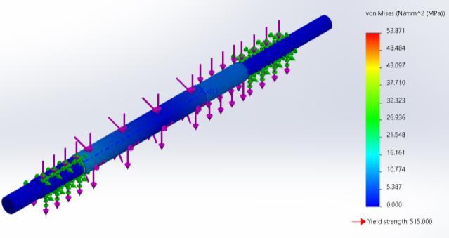
Fig -8:TorsionalStressAnalysis
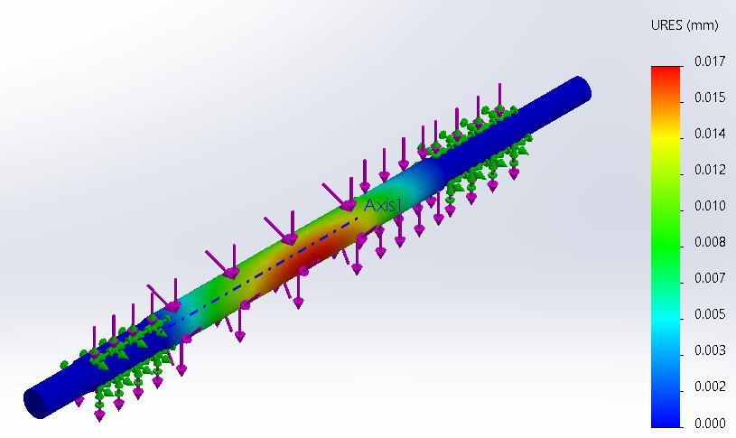
Fig -9:TorsionalDisplacementAnalysis
Table -3: ResultforAnalysisofRoller Sr.
7. RESULTS AND DISCUSSION
a) The capacity of coal at the outlet is increased due to designmodifications
b) Due to optimum material selection, the overall cost of manufacturingtheconveyorhasbeenreduced.
[1] Devendra kumar (2021) “Analysis & Prospects of ModificationinBeltConveyors”InternationalJournalof Engineering Research and Applications (IJERA) ISSN: 2248-9622.
[2] Chudasama Pratik Naresh & Darji Jaydeep Kanubhai, (2021),”Design, Analysis and Optimisation of Belt ConveyorforCoalApplication” ,InternationalJournalOf Engineering Research & Technology (IJERT) NTASU –2020(Volume09–Issue03)
[3] SayaliTodkar,(2018)“DesignofBeltConveyorSystem” International Journal of Science, Engineering and TechnologyResearch(IJSETR) Volume7,Issue7,July2018,ISSN:2278-7798
[4] Gupta,Ankit.(2015)"Failureanalysisofbeltinconveyor system for coal handling in thermal power plant.” SAMRIDDHI:AJournalofPhysicalSciences,Engineering andTechnology.3.10.18090/samriddhi.v3i2.1621
[5] AlanW.Roberts(2022),“Bulksolidsflowatthehopper feederinterfacewithspecialplaneflowconfiguration,” Powder Technology, Volume 403,2022,117372,ISSN 0032-5910,