
International Research Journal of Engineering and Technology (IRJET) e-ISSN: 2395-0056
Volume: 11 Issue: 05 | May 2024 www.irjet.net p-ISSN: 2395-0072
International Research Journal of Engineering and Technology (IRJET) e-ISSN: 2395-0056
Volume: 11 Issue: 05 | May 2024 www.irjet.net p-ISSN: 2395-0072
Pushkar Bendre1, Suyash Kadam2 ,
1,2 Department of Mechanical Engineering, Smt Kashibai Navale College of Engineering, Pune, Maharashtra, India
Abstract – The purpose of this paper is to select,design,and analyze an open differential for EFFIQUE-ADAS vehicle for Team Stallion Effi-cycle.EFFIQUE-ADASisasingle-seaterfourwheeled electric vehicle equipped with advanced drive assistance systems. The differentials play a crucial role in the power transmission of the vehicle at cornering conditions, improve stability enhance overall performance, thus improve vehicle dynamics which is essential in the competition. To focus on designing an efficient open differential, optimal standard design principles are used that eventually integrate with vehicle needs. The Design procedure is strictly followed from the SAE-NIS Effi-cycle’s 2024 rulebook, ensuring overall compliance with restrictions and guidelines throughout the entire design procedure.
Key Words: Open Differential, Effi que – ADAS, Stallion Effi cycle, Bevel Gear, Pinion, Centrepin, SOLIDWORKS, ANSYS.
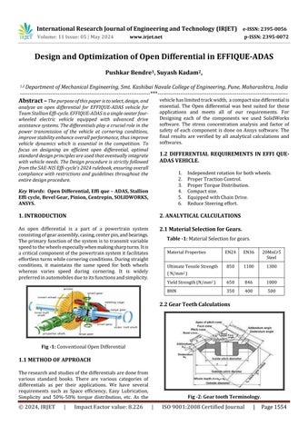
1. INTRODUCTION
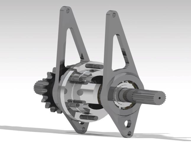
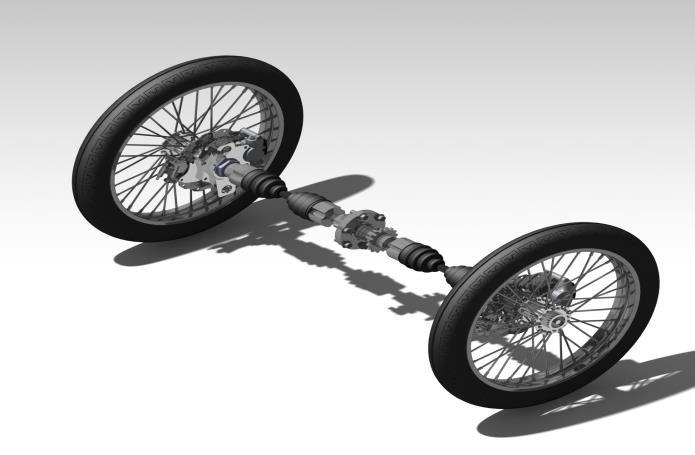
An open differential is a part of a powertrain system consistingofgearassembly,casing,centerpin,andbearings. Theprimaryfunctionofthesystemistotransmitvariable speedtothewheelsespeciallywhenmakingsharpturns.Itis acriticalcomponentofthepowertrainsystemitfacilitates effortlessturnswhilecorneringconditions.Duringstraight conditions, it maintains the same speed for both wheels whereas varies speed during cornering. It is widely preferredinautomobilesduetoitsfunctionsandsimplicity.
1.1
Theresearchandstudiesofthedifferentialsaredonefrom various standard books. There are various categories of differentials as per their applications. We have several requirements such as Space efficiency, Easy Lubrication, Simplicity and 50%-50% torque distribution, etc. As the
vehiclehaslimitedtrackwidth, acompactsizedifferentialis essential. The Open differential was best suited for those applications and meets all of our requirements. For Designing each of the components we used SolidWorks software. The stress concentration analysis and factor of safety of each component is done on Ansys software. The final results are verified by all analytical calculations and softwares
1. Independentrotationforbothwheels.
2. ProperTractionControl.
3. ProperTorqueDistribution.
4. Compactsize.
5. EquippedwithChainDrive.
6. ReduceSteeringeffort
2. ANALYTICAL CALCULATIONS
2.1 Material Selection for Gears.
Table -1: MaterialSelectionforgears.
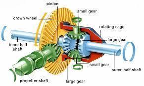
2.2 Gear Teeth Calculations
International Research Journal of Engineering and Technology (IRJET) e-ISSN: 2395-0056
Volume: 11 Issue: 05 | May 2024 www.irjet.net p-ISSN: 2395-0072
Module(m)=2mm
Power(P)=0.6kw
Np=450rpm
Material–20MnCr5Steel
BHN=500
Sut=1300N/mm2
Zp=12
Zg=16
Diameterofpinionandgear.
Dp=Zp×m=12×2=24mm
Dg=Zg×m=16×2=32mm
µp=tan-1 (Zp/Zg)=tan-1 (12/16)=36.38
µg=53.13
Virtualno.ofteeth.
Zp’=Zp/cos(36.86)=15
LewisFormFactorY=0.289fromStandardTable
σb=Sut/3=1300/3=433.33N/mm2
K=0.16×(BHN/100)2 =0.16×(500/100)2 =4
Q=2×Zg/Zg+Zptan(36.86)
=2×16/16+12tan(36.86)
=1.28
Ao=√(Dp/2)2+(Dg/2)2 =√(24/2)2+(32/2)2 =20mm
B=10morAo/3=20/3=6.67mm
Takewhicheverissmaller
P=2πNpT/60
0.6×103 =2π×450×T/60×103
T=9610.32Nmm
TangentialLoad
Pt=2T/Dp =2×9610.32/30
=720.38N
BendingStrengthofPinion
Sb=m×b×σb×Y×(1–b/Ao)
=2×6.67×433.33×0.289×(1–6.67/20)
=1326.46N
WearStrengthofPinion
Sw=0.75×b×Q×K×Dp/cos(36.86)
=0.75×6.67×1.28×4×24/cos(36.86)
=1038.29N
V=π×Dp×Np/60×103
=π×24×450/60×103
=0.56m/s
C=11400N/mm2 ,e=0.0125mm
DynamicLoad, Pd=21×V×(√C×e×b×Pt)/21×V+√(C×e×b×Pt)
=21×0.56×(√(11400×0.0125×6.67+707.38)/21×
0.56×√(11400×0.0125×6.67+707.38)
=228.33N
Peff=Cs×Pt+Pd
=1×720.38+228.33
=948.71N
ForBendingfailure,
Sb=Peff×Fos
1326.46=948.71×Fos
Fos=1.4
ForWearing/Pittingfailure, Sw=Peff×Fos
1038.46=948.71×Fos
Fos=1.10
MeanRadius,
Rm=(Dp/2–b×sinµ/2)
=24/2–(6.67×sin(36.86)/2)
=9.99mm=10mmapprox.
Tangentialload, Pt=T/Rm
=9610.32/10
=961.032N
Radialload,
Pr=Pttanα×cosβ
© 2024, IRJET | Impact Factor value: 8.226 | ISO 9001:2008 Certified Journal | Page1555
International Research Journal of Engineering and Technology (IRJET) e-ISSN: 2395-0056
Volume: 11 Issue: 05 | May 2024 www.irjet.net p-ISSN: 2395-0072
=961.32×tan(20)×cos(36.86)
=279.86N
Thrustload,
Pa=Pt×tanα×sinβ
=961.32×tan(20)×sin(36.86)
=209.88N
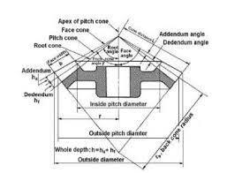
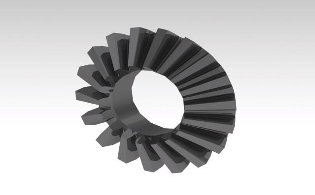
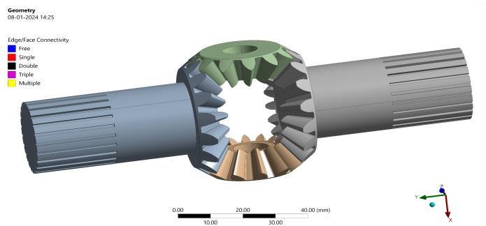
3.1 Gear and Pinion
Themodelwaspreparedbasedonthespaceavailabilityin thetransmissionsystem,aftergettingtheanalyticaldataby calculations. The gear pairs of bevel gears were designed thatgenerallyconsistoftwogearsandtwopinionsforbetter torque distribution. The material selected for bevel gear manufacturing is 20mnCr5 steel due to its numerous advantages that include Ultimate Tensile strength, yield strength BHN, etc. The length of the gears was decided consideringtheavailablespaceinthetransmissionsystem. Splinesareprovidedattheendofthegearforoutputspeed
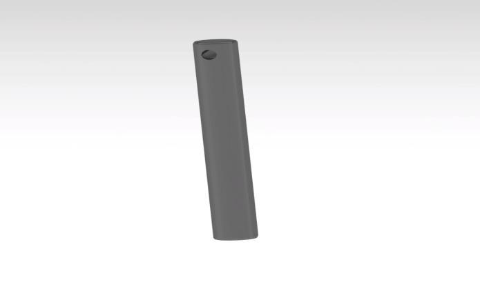
Wemadethecenterpintofitneatlyamongthegearpairs andbeeasytofixifneeded.Tokeepitlightbutstrong,we used20MnCr5steel.Wealsoaddedasmallholeatoneend sowecanattachitsecurelytothedifferentialcasingwitha nutandbolt.Thatway,itstaysinplaceandwon'tslipout.
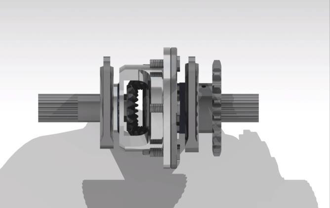
Thedecisionwasmadetodesignthecasingintwopartsfor easierassemblyandservicing.Webasedtheoveralldesign onhoweverythingfitsinside.Thelengthofthecasingwas determinedbythesizeofthesidegearsandtheplacementof thesprocket.Thetwocasingswereconnectedtoeachother usingpairsofnutsandbolts,andthenthecasingassembly was mounted onto a pair of bearings in the differential mountplates.
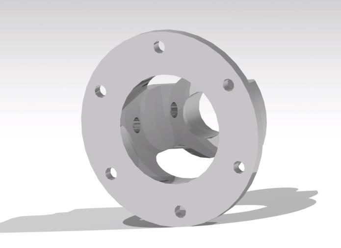
Fig -5 Differential Casing
TheMaterialusedformanufacturingthecasingisEN24.
International Research Journal of Engineering and Technology (IRJET) e-ISSN: 2395-0056
Volume: 11 Issue: 05 | May 2024 www.irjet.net p-ISSN: 2395-0072
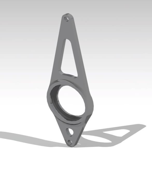
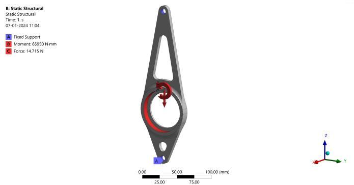
The design of the differential plate took into account the spaceconstraintsimposedbythesprocketandtheavailable mountingpointsonthechassisforattachingthedifferential. To ensure secure mounting, weadded a small holeat one endofthedifferentialplateforattachingaboltthatwould pass through both mounting plates, keeping them firmly alignedinoneplane.
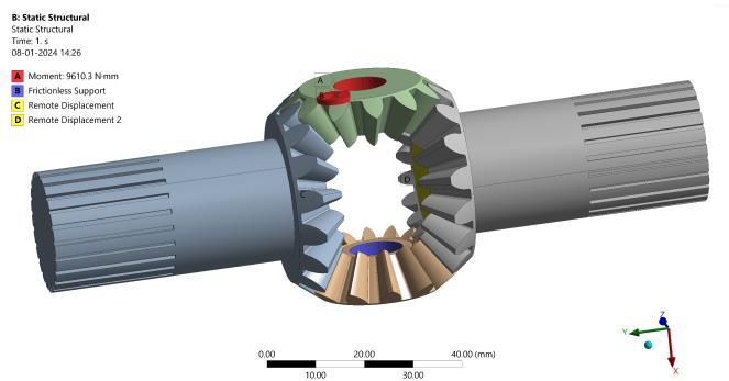
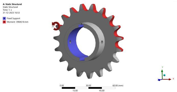
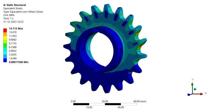
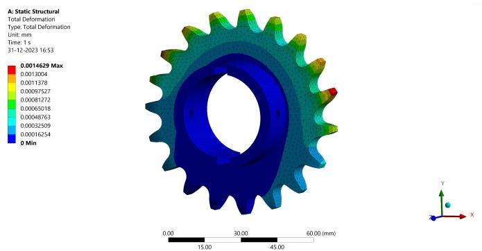
4.
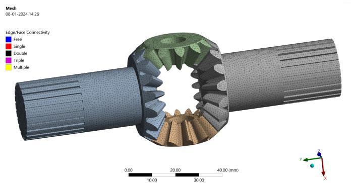
We conducted static structural simulations for all the components.Sincethesoftwaredidn'tautomaticallyselect material properties, we inputted them manually. Once we determinedthematerialproperties,weimportedtheCAD modelintoANSYSWorkbench.Then,wecreatedthemesh andappliedanalyticalforcestothecomponents.Wechose thedesiredsolutions,suchasvonMisesstressesandtotal deformation,andobtainedtheresultsweneeded.
International Research Journal of Engineering and Technology (IRJET) e-ISSN: 2395-0056
Volume: 11 Issue: 05 | May 2024 www.irjet.net p-ISSN: 2395-0072
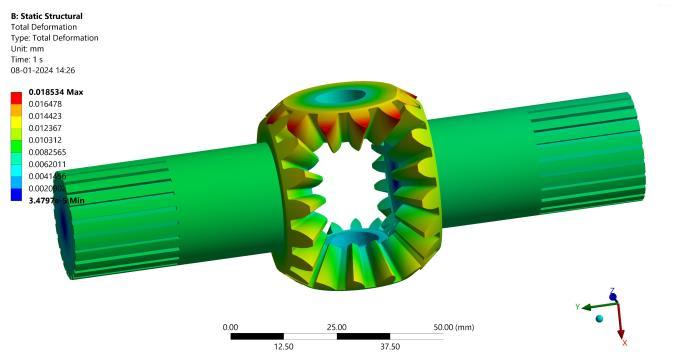
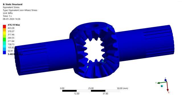
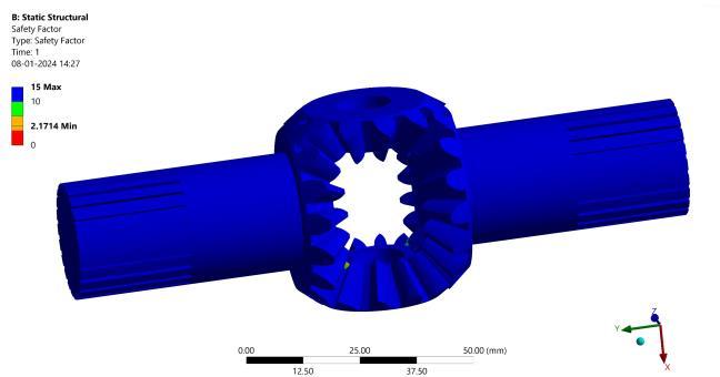
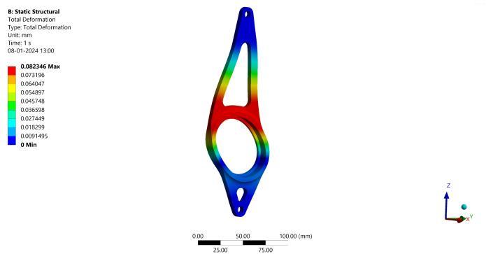
4.2 Casing of Material EN 24
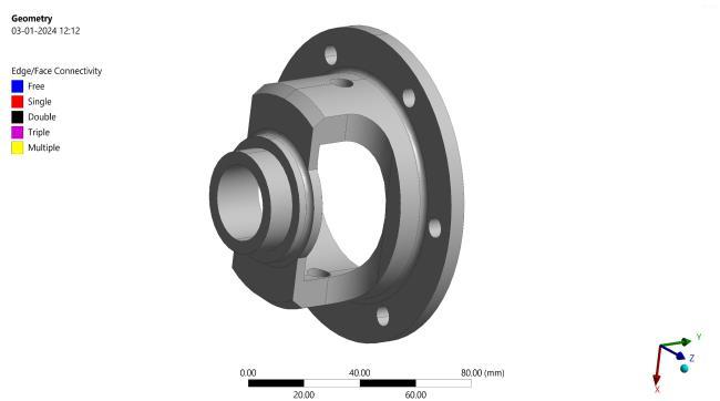
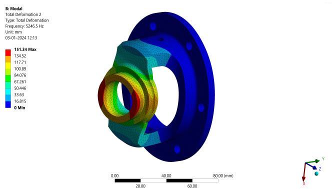
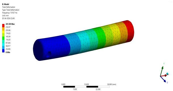
Fig – 16: Deformation in Differential Casing 4.3 Centre Pin of Material 20MnCr5 Steel
International Research Journal of Engineering and Technology (IRJET) e-ISSN: 2395-0056
Volume: 11 Issue: 05 | May 2024 www.irjet.net p-ISSN: 2395-0072
4.4 Differential Mount Plate of Material Aluminum 6061 T6
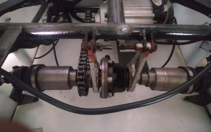
5. EXPERIMENTAL SETUP AND TESTING
Thepinionmaterialwastougherthanthedifferentialcasing, soweinsertedbushbetweenthepinionsandthecasingto prevent wear from metal-to-metal contact. Both the differentialcasingandmountplatesweremachinedusinga computer-controlled Vertical Machining Centre (VMC). Whenwemeasuredthecompleteassemblyona weighing machine,ittotaled2.6kg.Wethenassembledtheentireunit ontotheEffi-queADASvehicle.
We putthedifferential throughrigorous testingfor30-40 days on off-road terrain, subjecting it to sharp corners, obstacles,sand,gravel,bumps,anddepressionsfor6-7hours eachday.Duringtesting,weobservedthevehiclenavigating sharpcornersandvisuallyinspectedthetreadpatternofthe tiresandthewearofthegearteeth.
International Research Journal of Engineering and Technology (IRJET) e-ISSN: 2395-0056
Volume: 11 Issue: 05 | May 2024 www.irjet.net p-ISSN: 2395-0072
6. CONCLUSION
Thedifferentialassembly,onceinstalledintheEffi-queADAS vehicle,meetsallthedesignrequirements.Itdemonstrates remarkable durability on rough terrain and under critical operatingconditions.Throughouttesting,wedidn'tobserve any traction issues, and the vehicle could navigate sharp turnswithoutlosingtraction.Thisconfirmsthattheinitial objectiveofthedifferentialforthetransmissionsystemof the Effi-que ADAS vehicle has been successfully achieved. This outcome paves the way for further research and developmentonthesaidsystem.
7. ACKNOWLEDGEMENT
IamprofoundlygratefultoTeamSTALLIONEFFI-CYCLEand mycollege,SKNCOE,fortheirinvaluablesupportinfinalizing thispaperwithinashortperiodandintegratingitintotheir Effi-queADASvehicle.Theirdedicationandassistancehave beeninstrumentalinbringingthisprojecttofruition,andI amtrulythankfulfortheircollaborationandexpertise.
[1] V.B.Bhandari,‘DesignofMachineElements’
[2] V.D.Kodgire,‘MaterialScienceandMetallurgy’
[3] Darle W. Dudley, 1954, Hand book of practical gear design Maitra, G.M, 2004, Hand Book of Gear Design, TataMcGrawHill,NewDelhi
[4] Milliken, William F., Milliken, Douglas L, “Race Car VehicleDynamics,”1985.
[5] CarrollSmith,”Tunetowin,”,1989.


Mr.PushkarA.Bendre BEMechanical, SKNCOE,Pune Maharashtra INDIA
Mr.SuyashV.Kadam BEMechanical, SKNCOE,Pune Maharashtra INDIA