
International Research Journal of Engineering and Technology (IRJET) e-ISSN: 2395-0056
Volume: 11 Issue: 05 | May 2024 www.irjet.net p-ISSN: 2395-0072
International Research Journal of Engineering and Technology (IRJET) e-ISSN: 2395-0056
Volume: 11 Issue: 05 | May 2024 www.irjet.net p-ISSN: 2395-0072
Prof. R.H. Tike1,Atharva V. Shembavnekar2 , Jay M. Desai3 , Siddharth S. Boralkar4
1 Faculty of Mechanical Engineering, Pune Vidyarthi Griha’s College of Engineering and Technology, & GKPIOM, Savitribai Phule Pune University, Pune, Maharashtra, India
2,3,4 Student of Mechanical Engineering, Pune Vidyarthi Griha’s College of Engineering and Technology, & GKPIOM, Savitribai Phule Pune University, Pune, Maharashtra, India
***
Abstract - Theproject's goal is to improvevehicledrive shafts by investigating performance characteristics, materialchoices,andstructuralintegrity.Torque,stress, and vibration are all examined to meet safety criteria throughtheoreticalcalculationsandsimulations.Surface treatmentsareusedtoimprovethelongevityofmaterials by reducing wear and corrosion. Iterative optimization and validation through testing ensures reliability. The findings provide useful information for improving drive shaft designs in a variety of technological applications. Thereislittleresearchintooptimaldesigncharacteristics like as motor placement and torque distribution, which can improve overall vehicle dynamics and energy economy.Investigatingthesegapscouldprovidevaluable insights into the field, and most budget vehicles lack hybrid technology and rear wheel drive. In this project, therear wheel is powered by an electric motor, for which a drive shaft has been designed and manufactured. Exploring trailing arm modifications while retaining the original equipment manufacturer (OEM) knuckle and shaft provides a nuanced option for improving vehicle performance. This adjustment allows for fine-tuning of suspension dynamics, such as camber and toe angles, which improves handling, traction, and responsiveness. The basic objective is to create a rear wheel drive shaft with an optimized diameter to improve power transmission efficiency while minimizing energy loss through the electric motor. The alteration of the vehicle will aid in maintaining and managing fuel usage effectively. Overall vehicle performance might be improved to cut emissions, representing a substantial leap in hybrid technology.
Key Words: Drive shaft, FEA Analysis, Material Study, EV Kit, Testing Specimen.
Thisprojectentailsathoroughevaluationofthecurrentaxle systemtoidentifyopportunitiesforimprovementandthe incorporation of hybrid components. It emphasis on improving the axle's structural integrity while also introducing a drive shaft and knuckle to power the rear wheels,weightdistributionachievedbycenteringthemotor,
and compatibility with electric drive components. Design changes,materialselection,andtechnicalintegrationsmay be made to assure the Swift Dzire's smooth hybrid functionality,increasedefficiency,andoverallperformance. The project also includes the creation of a versatile shaft with variable discontinuities that can adjust to diverse loadingconditions,assuringoptimalperformance.[2].Solid shaftsarepreferredoverhollowshaftsbecauseof:
MoreStrengththanhollowshaftunderbendingforces.
Less diameter shaft could be used to make a compact assembly.
Easymachining
Costefficient.
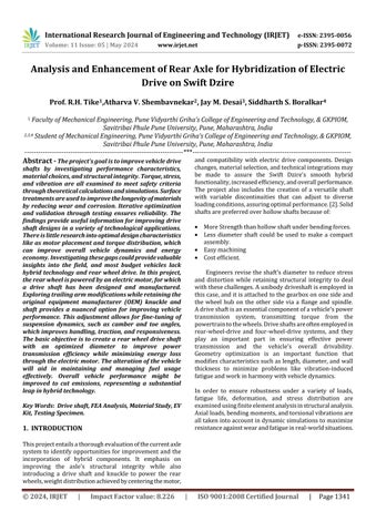
Engineers revise the shaft's diameter to reduce stress and distortion while retaining structural integrity to deal withthesechallenges.Aunibodydriveshaftisemployedin thiscase,anditisattachedtothegearboxononesideand the wheel hub on the other side via a flange and spindle. Adriveshaftisanessentialcomponentofavehicle'spower transmission system, transmitting torque from the powertraintothewheels.Driveshaftsareoftenemployedin rear-wheel-drive and four-wheel-drive systems, and they play an important part in ensuring effective power transmission and the vehicle's overall drivability. Geometry optimization is an important function that modifiescharacteristicssuchaslength,diameter,andwall thickness to minimize problems like vibration-induced fatigueandworkinharmonywithvehicledynamics.
In order to ensure robustness under a variety of loads, fatigue life, deformation, and stress distribution are examinedusingfiniteelementanalysisinstructuralanalysis. Axialloads,bendingmoments,andtorsionalvibrationsare alltakenintoaccountindynamicsimulationstomaximize resistanceagainstwearandfatigueinreal-worldsituations.
International Research Journal of Engineering and Technology (IRJET) e-ISSN: 2395-0056
Volume: 11 Issue: 05 | May 2024 www.irjet.net p-ISSN: 2395-0072
1. P.Jayanaiduet.al,hadreportedthatTi-6Al-7Nbtitanium alloysareusedinplaceoftraditionalsteeldriveshaftsin the case study in this research because of its strong toughness and small weight. The ANSYS software was used to perform the simulation and impose a fixed boundaryconditionononeendoftheshaftandatorque of3000rpmontheother.Theshaftmodelwasmadein Pro-E. The study produced the maximum stress and equivalent stress parameters after computing deformation.Thisindicatesthatthetitaniumalloy(Ti6Al-7Nb)isabetterchoiceforadriveshaftduetoitslow weightandcompletedeformationofsteelandtitanium alloy.
2. Dr.B.P.Patel1et.al,hadexaminedthatthecoreofthis study was a detailed analysis of shaft design under varyingloadingconditionsanddiscontinuities.Theyhave also previously published on fatigue fractures, shaft design,andfailureanalysisusingavarietyofanalytical techniques, including mathematical techniques. On the other hand, they note less about discontinuities and combinationloadingandadvisethatresearchfocusonit.
3. He Pan1 et.al, had investigated a thorough analysis of several lightweight, extremely durable materials. He begins by classifying steel into two categories: highstrength steel and advanced high-strength steel. Advanced high-strength steel is defined as having a resistanceratioofatleast700MPa.Theweightofcarsis saidtoberesponsiblefor60%offuelconsumption.They also aim to produce material that is lightweight and strong. The Japanese developed BL385, SA440, and SA630,whichhave tensilestrengths ofupto550MPa, 590MPa,and780MPa,respectively.Chinaneedsalotof HSSsincethebuildingindustryutilizesitsomuch.Only steel high-strength alloys are more in demand than aluminumalloysaslow-weight,high-strengthmaterials. High-strength aluminum alloy's performance: Lithium and Al-Li alloy are used to make the lightest metal product. The density may decrease by 3% and the modulemayriseby5%forevery1%increaseinlithium concentration in the aluminum alloy. The lightest structuralmetalismagnesiumalloy,whichhasadensity of 1.75g/cm3. It is made up of around two thirds
aluminumalloyandonequartersteel.Tensilestrengths of up to 1500 MPa are achieved by titanium alloys in contrasttoultra-high-strengthsteel.
4. Prof.VijoyKumaret.al,hadoutlinedhowthisresearch includes a thorough analysis of roller shaft failures, whichmaybeimprovedbyemployingmechanicalrepair approaches that are preventive. He mentioned several earlierresearchinvestigationsthatlookedatdefectsand workingconditions.Ananalysisdemonstrates thatthe conveyor's pulley's shaft breaking is due to fatigue. Anotherexperimentfoundthatthereducedtrueradius of the chamber caused the draft fan shaft of a steam boiler to collapse. An extended examination of the locomotive's turbocharger malfunction. Investigations into Charpoy Fractography employing SEM, spectrometers, spectroscopes, and Finite Element Analysis using ANSYS have been made possible by the introductionofbearingsleeves.
5. AniketBhilare1et.al,hadstatedthatthisstudypaper's objective is to lighten the car's weight by changing its numerous components. The study of the driveshaft revealed two examples of completed analyses: the maximumprincipalstressandtheequivalentstress.
6. Li-HuiZhaoaet.al,hadusedtwodriveshaftstoexamine thefailureandunderlyingcauseofarecurringdriveshaft fracture. Drive shafts were discovered to have fatigue failure indicators during the test while they were in operation. The FEA performed while the machine was running at high torque revealed an apparent stress concentrationthatiscompatiblewiththelocationofthe fracture site. Moreover, a limited fillet radius causes unduestress,whichisthoughttobethemaincauseof thedriveshaftfailure.
7. SamuelO.Afolabiaet.al,hadconfirmedandsaidthata PalmKernelcrackingmachinewitha20mm&30mm shaft diameter was examined in this study using FEA analysis and 3D modeling. This demonstrates that the optimalconfigurationhastheloadandVonMisesstress of102.4MPaformildsteelcomposition,withatotalyield stress of 156 MPa. The best shaft diameter for production,accordingtothedata,is20mm.
8. Carlos M.S. Vicente et.al, their paper focuses on a connectedshaftshredderfailurethathasbeenevaluated. The failure was examined using every experimental technique,inadditiontostatisticalevaluationsintended to identify the fundamental causes of connected shaft failure. The shaft collapsed due to fatigue at a plane perpendiculartotherotationaxis,closetotheconnecting transverseaperture.
International Research Journal of Engineering and Technology (IRJET) e-ISSN: 2395-0056
Volume: 11 Issue: 05 | May 2024 www.irjet.net p-ISSN: 2395-0072
Tooptimizediameterofshaftforrearwheeltotransmit powerthroughelectricmotor.
Develop a drive shaft design that maximizes power transmissionefficiency.
Tominimizefailureofshaftathighloadingconditionon unevenroadsurface.
To optimize the design based on analysis results, ensuring it meets safety standards and regulatory requirements.
Electricbatterypacksareagreatwaytoreducefuel costs and convert existing front-wheel drive cars into hybrid vehiclesbyaddingabatterypackandmotortotherearand creatingacompletelyhybridvehiclebytransmittingpower totherearwheels.Thisisespeciallyusefulgiventherisein carbon credits and pollution these days.
Themajorityofordinarycarstransferpowerthroughtheir front wheels; the rear wheels are devoid of any kind of power-producingequipment.Inordertoenablerearwheel drive with the installation of an electric motor to transfer power, this project's design incorporates half shaft calculationsandanalysisfortherearwheels.
Methodology for Designing, Analyzing, Material Selection, Validating,Testing,andManufacturingofaDriveshaft:
Designing includes outlining the specifications and limits, suchastorque,speed,andavailablespace.
Analysishelpstomodelstress,strain,andvibrationunder variedoperatingconditions.
MaterialSelectionincludesselectingmaterialsaccordingto their mechanical attributes, including fatigue resistance, modulusofelasticity,andtensilestrength.
Verifying and making sure the design is sound by using computer simulations and computations. Making sure it complieswithindustrystandardslikeASTMorISO. Production includes selection of suitable production techniques, such as heat treatment procedures and machiningbasedonmaterialanddesignspecifications. Testingtoconfirmtheperformanceofthedesign,dohandsontestingusingprototypes.
Analyzingperformanceinreal-worldscenariostofindany possibleproblems.
By following this comprehensive methodology, you can ensure the successful design, analysis, material selection, validation, testing, and manufacturing of a driveshaft, meetingperformancerequirementsandindustrystandards.
MaterialProperties:
MechanicalpropertiesofselectedAISI4130material:
ElasticModulus–210000N/mm^2
ShearModulus–80000N/mm^2
Poisson’sRatio–0.29
UltimateTensileStrength–560N/mm^2
YieldTensileStrength–460N/mm^2
Specificationsofcar:
Thespecificationsofthecaronwhichtheprojectiscarried out:
Make&Model–2020SwiftDzire.
KerbWeight–915kg.
Considering the car in fully loaded condition with 5 passengers each of 100 kg weight. There-fore total weight includingpassengers–915+500*9.81=13881.15N
TechnicalSpecificationsofmotor: Torque–100000n-mm.
Weight–28kg.
Type–ReluctantMotorDrive.
Calculations:
LoadPathCalculations–CalculationofTorsionalForce:
Wehave, Mt/J=Gθ*r/L where,
Mt=torque.
J=polarmomentofinertia.
G=modulusofrigidity.
θr=angleoftwist.
L=lengthoftheshaft.
TocalculatePolarMomentofInertia,
J= π(R)^4/2……………………….(forsolidshaft)
J=3.14(11.5)*4/2
J=27473mm*4
International Research Journal of Engineering and Technology (IRJET) e-ISSN: 2395-0056
Volume: 11 Issue: 05 | May 2024 www.irjet.net p-ISSN: 2395-0072
TocalculateTorsionalForce,
Mt/J=Gθr/L
100000/27473=80000*θr/1000
θr=100000*1000/27473*80000
θr=0.0250radian
θr=2.6094degree
TocalculateTorsionalStress,
τ=Mt/J.R
τ=100000/27473*11.5
τ=41.85N/mm^2
TocalculatePermissibleTensileStrength,
σt=Syt/FOS=460/3
σt= 155N/mm^2
TorqueandDiameterequation,
T=π/16.τ.d^3
100000=3.14/16*41.85*d^3
d^3=1600000/3,14*41.85
d^3=12175.72
d=23mm
Hence the above diameter should be considered for the designofsolidshaft.
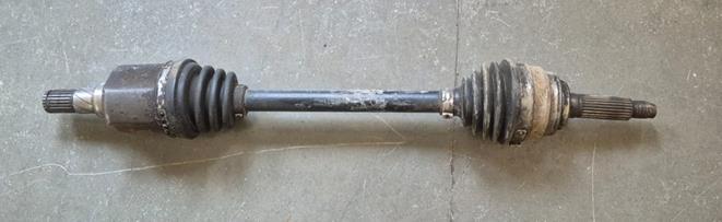
7. Cad Design
A. Pre-processing: Pre-processing for driveshaft torsional analysis involves creating a geometric model, assigning materialproperties,consideringmaterialnonlinearity.
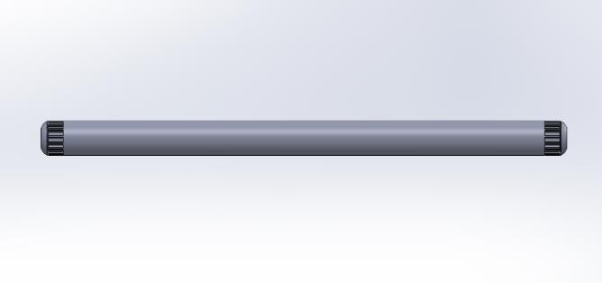
Fig:- 3 MaterialSelection
ThematerialassignedisAISI4130becauseofitsexcellent strengthandtoughness.
TABLE 1 MaterialPropertiesofAISI4130
AISI 4130
Properties
ElasticModulus 210000N/mm2
ShearModulus 80000N/mm2
Poisson’sRatio 0.29
UltimateTensileStrength 560N/mm2
YieldTensileStrength 460 mm2
B. PostProcessing:Postprocessingreferstomeshingof thecomponentwithproperelementsize.Then applyingboundaryconditionslikeapplicationofload/ moment,providingconstraints.
TABLE 2 TorsionAnalysisBoundaryConditions Sr
International Research Journal of Engineering and Technology (IRJET) e-ISSN: 2395-0056
Volume: 11 Issue: 05 | May 2024 www.irjet.net p-ISSN: 2395-0072
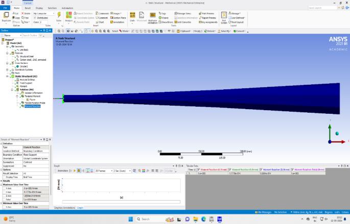
Thedriveshaftmomentreaction,alsoknownasthetorque reaction, refers to the reactive force experiencedbythevehicle.
C. Solution:Solutionfoundfortheanalysisofthedriveshaft include finding of angle of twist, total deformation, maximumequivalentstressandfactorofsafety.
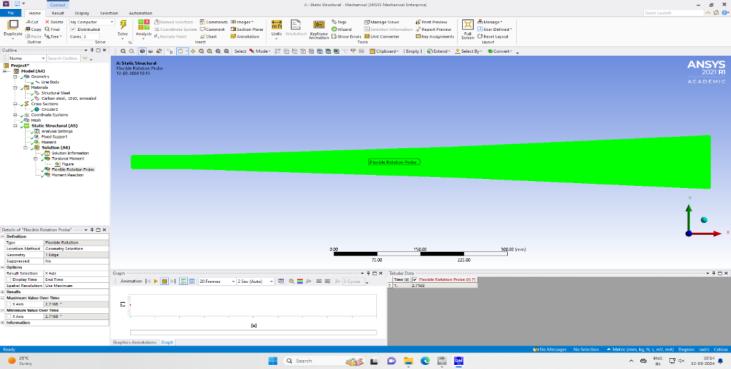
5 AngleofTwistfromtheanalysiswasfoundtobe 2.7168
Thedriveshafttorsionalmomentreferstothetwistingforce applied to the drive shaft, resulting in torsional stress anddeformation. Torsional moment of 100000 n/mm is appliedintheaboveanalysis.
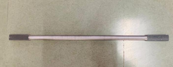
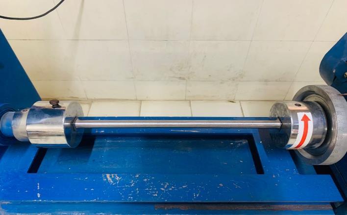
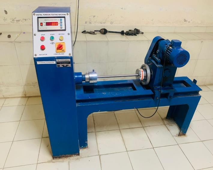
Thetestingwasbeingperformedbyusonatortionaltesting machine.Weperformedthetorsiontestonthespecimenof material AISI4130of total lengthof 540mm with the test piecelengthof400mm.Thetestingwasperformedtocheck for the material strength when it undergoes a torsional momentwithmagnitude100N/m.Therequirementsfrom thetestingwereofthepermissibletorqueandtheangleof twistforthatamountoftorque.Itwasanon-destructivetest inwhichweappliedatorqueofmagnitude120N/msoasto gettheangleoftwistofthespecimen.
10. Validation
TABLE 3 ComparisonofAngleofTwist
CAL
International Research Journal of Engineering and Technology (IRJET) e-ISSN: 2395-0056
Volume: 11 Issue: 05 | May 2024 www.irjet.net p-ISSN: 2395-0072
Angleoftwistanalyticalpercentageerror=(2.7168–2.6094/2.6094)*100=4.1%
Angleoftwistanalyticalpercentageerror=(2.7659–2.6094/2.6094)*100=6%
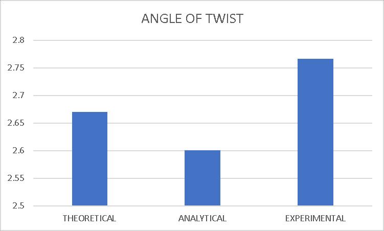
Fig:- 9 Comparisonofangleoftwistvalues. 11. Conclusion
Fromtheexperimentalandanalyticaldata,wecanconclude that the driveshaft which is being designed and manufactured is completely safe and follows the internationalsafetystandards.Thedriveshaftcanbeusedto transmitatorqueofmagnitude100Nmwithoutanyfailure andwithhighefficiency.Itisconcludedthatthedriveshaft so manufactured in this project has greater strength, durability, and can be used in different automobiles to transmitpowerfromthepowertraintothedrivenwheels. Theresultswegotfromthetorsiontestwerevalidatedand the percentage error between the analytical and experimental result was quite negligible, as per the internationalsafetystandards.
ACKNOWLEDGEMENT
Prof. R.H.Tike Assistant Professor, PUNE VIDYARTHI GRIHA’SCOLLEGEOFENGINEERING,Punehasguidedand mentoredduringtheprocessoftheproject.Sincerethanks toPVGCollegeforprovidingmaterialtestingfacilityintheir laboratory.
1. P. Jayanaidu, “Analysis of a Drive Shaft for Automobile Applications,”IOSRJ.Mech.Civ.Eng.,vol.10,no.2,pp. 43–46,2013.
2. B.Patel,H.RPrajapati,andD.BThakar,“CriticalReview onthedesignofshaftwithmultiplediscontinuitiesand combinedloadingsICCIET–2014,”no.May2017,pp.7–14,2014.
3. Y. Zhang, “Development and application of lightweight highstrengthorganicmaterials,”MATECWebConf.,vol. 207,pp.1–4,2018.
4. V. Kumar, “A Review of Fundamental Shaft Failure Analysis,” Int. Res. J. Eng. Technol., pp. 389–395, 2016, [Online].
5. P.Dhamdhere,“DesignandAnalysisofDriveShaftUsing DifferentMaterials,”no.1,pp.412–420,2018.
6. L.H.Zhao,Q.K.Xing,J.Y.Wang,S.L.Li,andS.L.Zheng, “Failureandrootcauseanalysisofvehicledriveshaft,” Eng.Fail.Anal.,vol.99,no.January2018,pp. 225–234, 2019.
7. S.O.Afolabi,B.I.Oladapo,C.O.Ijagbemi,A.O.M.Adeoye, andJ.F.Kayode,“Designandfiniteelementanalysisofa fatiguelifepredictionforsafeandeconomicalmachine shaft,”J.Mater.Res.Technol.,vol.8,no.1,pp.105–111, 2019.
8. C.M.S.Vicente,M.Sardinha,andL.Reis,“Failureanalysis ofacoupledshaftfromashredder,”Eng.Fail.Anal.,vol. 103,no.January,pp.384–391,2019.
9. AZOM.comformaterialproperties.
10.V.B.BhandariBookfordesigncalculationofdriveshaft.
© 2024, IRJET | Impact Factor value: 8.226 | ISO 9001:2008