
International Research Journal of Engineering and Technology (IRJET) e-ISSN: 2395-0056
Volume: 11 Issue: 05 | May 2024 www.irjet.net p-ISSN: 2395-0072
International Research Journal of Engineering and Technology (IRJET) e-ISSN: 2395-0056
Volume: 11 Issue: 05 | May 2024 www.irjet.net p-ISSN: 2395-0072
Darshan Ramachandra Todkar 1 , U.R. Awari 2 ,
1P.G. Student, Dept. of Civil Engineering, AISSMS College of Engineering, Pune, Maharashtra State, India
2Professor, Dept. of Civil Engineering, AISSMS College of Engineering, Pune, Maharashtra State, India
Abstract - As the wind blows against a building, the resulting force acting on the elevations is called the ‘wind load’. The building’s structural design must absorb wind forces safely and efficiently and transfer them to the foundations in order to avoid structural collapse. Wind loads will typically depend on the wind velocity and the shape(andsurface)ofthebuilding,andiswhytheycanbe difficult to predict accurately. The building shape may exacerbate any over- or under-pressure effects. On the windwardside(facingthewind),windoverpressuresmay blow windows in, while on the leeward side (sheltered from the wind) under-pressure (suction) may blow windowsout.Hill buildings differfromplains buildings in that they are highly uneven and asymmetrical in horizontal and vertical planes, as well as torsionally linked. Because very few plain grounds are available in hilly locations, structures must be built on slopes. R.C.C structures with columns of varying heights at same story have sustained more harm in the columns with lesser heightthaninthecolumnswithgreaterheightinthesame floor.AcasestudyB+S+18buildinghasbeenconsideredin this research work. Step back and step back set back configurations are included to the actual plan of the building in our research. Building is considered resting sloping ground with varying angle of 0°, 15°, 20° and 25°. AftertheanalysiswecanconcludethatSlopeofbuildingis maintained by increasing the height of columns from one side as compared to other side which creates additional torsional effect on the building. There is significant increase in maximum story drift of the structure due to slopingground.Alsothere isreductioninmaximumstory drift for step back set back configuration as compared to stepbackconfiguration.
Key words: Wind load analysis, step back, step back set back, ETABS, story drift
Every building's structure is susceptible to many loads,thefirstofwhichisgravity'spullonthestructure.In a similar vein, the "live load" the weight of the people, furnishings, fixtures, etc. must be supported by the building. In addition to bearing its own weight, the structure must withstand loads from the wind, an earthquake, etc. Always design and build buildings, other structures, components, and cladding to withstand wind loads.
The force that results from wind blowing against a building and acting on its heights is referred to as the "wind load." To prevent structural collapse, wind forces must be safely and effectively absorbed by the building's structural design and sent to the foundations. Wind loads can be challenging to anticipate with accuracy since they usually depend on the wind velocity and the form (and surface) of the building. Any consequences of over- or under-pressure may be exacerbated by the design of the building. Wind overpressures on the windward side (facing the wind) can force windows in, while under pressure(suction)ontheleewardside(shelteredfromthe wind)canforcewindowsout.Aglass-cladbuildingwitha verysmoothprofilewill tendtodeflectthewindfarmore effectively than a sculpted or textured profile, as will a circularbuildingcomparedtoasquareshape.
Any kind of structure's design must take wind load into account. The load exerted by wind on a structure's exterior is measured in kN per square meter. This is contingentupon:
• Theangleatwhichthewindstrikesthestructure
• Theshapeofthestructure(height,width,etc.)
Strengthening vulnerable building areas is necessary to prevent wind damage. The foundation, roof, and walls all need to be sturdy, as do the fasteners that hold them together. A continuous load path from the roof to the foundation connections that hold all structural components together and are capable of withstanding various wind loads that could push and pull on the building during a storm is necessary for a structure to withstandhurricanesandlighttornadicwinds.
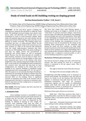
Windexertsthreetypesofforcesonastructure:
• Uplift load - Wind flow pressures that create a strongliftingeffect,muchliketheeffectonairplanewings. Wind flow under a roof pushes upward; wind flow over a roofpullsupward.
• Shear load – Horizontal wind pressure that could causerackingofwalls,makingabuildingtilt.
• Lateral load – Horizontal pushing and pulling pressureonwallsthatcouldmakeastructureslideoffthe foundationoroverturn.
International Research Journal of Engineering and Technology (IRJET) e-ISSN: 2395-0056
Volume: 11 Issue: 05 | May 2024 www.irjet.net p-ISSN: 2395-0072
Elevatedwindpressurehasthepotential tobring down doors and windows, tear off roof decking and roofing, and demolish gable-end walls. Particularly vulnerable to damage are roof overhangs and other elements that have a tendency to trap air beneath them, creating strong uplift forces. Broken windows and doors putthebuilding'scontentsatriskofsignificantharmfrom waterintrusionandinternalwindpressure.
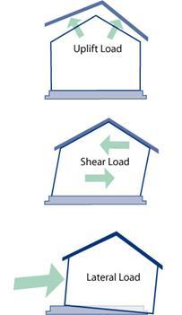
India's northeast and north-east contain sizable areasofhillcountry.Theregionisexperiencingasurgein demandformulti-storyRCframedbuildingsonhillslopes due to its fast urbanization and economic progress. The rise in construction activity is contributing to the growth in population density. In contrast to plain buildings, hill buildings are torsionally linked, very uneven, and asymmetrical in both horizontal and vertical planes. In mountainous areas, there isn't much level ground, therefore buildings have to be constructed on slopes. When lateral loads occur in RC frame buildings with columns that differ in height within a single level, the shortercolumnsexperiencegreaterdamagethanthetaller columnsonthesamefloor.
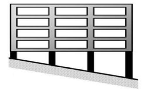
Short columns have poor behaviour because, during lateral loading like wind/seismic, tall and short columnswiththesamecrosssectionmovehorizontallyby thesameamount,asshowninFigure2.Theshortcolumn, on the other hand, is stiffer than the tall column, and so attracts more earthquake force. A column's stiffness indicates its resistance to deformation; the higher the stiffness, the greater the force required to deform it. Due to variations in mass and stiffness distributions on different vertical axes at each floor, these buildings becomehighlyirregularandunbalancedduetothevaried designsofbuildingsinhillylocations.Duetothatdifferent configuration has been seen as shown in Figure-3 (a) and (b).
Fig -3: (a) step back building (b) step building set backbuilding
Shreya Manduskar and V. S. Shingade (2023) considered 3D building frames of 25 storied building resting on flat terrain and sloping ground. Slopes of 20°, 30°, and 40° were taken into consideration for sloping ground.Theyweretobeexaminedatthreedifferentwind speeds:39m/s,47 m/s,and55m/s.Theextendedthreedimensional analysis of building systems, or ETABS, software can be used for the modeling and analysis. They cametotheconclusionthatbaseshearoutcomesforlevel terrain and all sloping angles were almost comparable. Resultsofearthquakedisplacementarefoundinbuildings withvaryingslopingterrain,includingflatterrain,20-,30,and40-degreeslopes,whichwerenearlyequivalentinall sloping-anglestructures.Resultsforwinddisplacementat basic wind speeds of 39 m/sec were obtained for level ground, 20 m/sec, 30 m/sec, and 40 m/sec sloping ground.Sincewinddisplacementriseswithslopeangle,it follows that an increase in ground slope will likewise result in an increase in wind displacement. When compared to a building lying on level ground, the displacementroseby5.6%fora20-degreeslope,7.5%for a30-degreeslope,and9.7%fora40-degreeslope.[1]
Ms. Khan Shaima Khan Iftekhar Khan, Mr. Aakash Suthar (2023) prepared 36 models for the interaction between tall buildings and wind on flat and sloping ground,specificallyfocusingonthe northernpartofIndia with high wind flow. An analysis was conducted on reinforced concrete structures with varying heights (G+5, G+10, and G+15) in different wind zones on both level
International Research Journal of Engineering and Technology (IRJET) e-ISSN: 2395-0056
Volume: 11 Issue: 05 | May 2024 www.irjet.net
ground and incline surfaces (0°, 10°, 20°, and 30°). Three distinct types of models were used to conduct wind load analyses for each zone using the ETABS software. The resultsweregood whenthe taledisplacement, story drift, and mode period were also examined. Comparisons were also made between software and manual computation results.Theycametotheconclusionthat,incomparisonto structuresonlevelground,thoseonslopingterrainexhibit a larger maximum displacement, which may result in dangerous circumstances. The 15-story building has the longest period at both the top and bottom storeys, accordingtothemodeshapestudy.Thenumberofstories and slope both increase story drift, story displacement, and mode period. But as the number of stories increases, themedianperiodgetsshorter.[2]
Pradeep Sivanantham et. al. (2023) represented an experimentalandanalyticalinvestigationofthebehaviour ofreinforcedconcreteframesandtheirresponseinsloped regions of hills, in which global retrofitting techniques wereadoptedbyproviding solidinfillintheshortcolumn effectzoneforthecolumnsinthesamestoreyofdifferent heights. The influence of infill on the short column effect under lateral cyclic loads was studied numerically. It was shownthat masonryinfill significantly boosted thelateral load-carryingcapabilitybyupto50%ascomparedtobare reinforced concrete frames. Meanwhile, the energy dissipationcapacityoftheframeroselinearly.Thevarious behaviors of the reinforced concrete structure, such as ultimate load displacement, crack pattern, energy dissipation, and energy absorption, were studied when infillwasaddedtotheframeusingtheshortcolumneffect. The lateral strength and energy dissipation capability of the reinforced concrete structure were enhanced by a factorof2.45withtheuseofasolidinfill.Incomparisonto the reinforced concrete frame without infill, the short column effect and the damage development on the reinforcedconcreteframewithinfill werelessaffected by lateralstress.[3]
Rayudu Jarapala, Arun Menon (2023) presented a comprehensive review of the classification of sloping ground buildings, their source of irregularity, parameters influencing seismic response, irregularity and storey damagedescriptors,andvulnerabilitymethodstoquantify their seismic performance. Lastly, various seismic retrofit techniques were also discussed in order to increase seismic performance. In structures with sloping terrain, six main typologies that are commonly found in practice were found. The most important factors influencing earthquake performance were irregular geometry, storey ratio, slope angle, and foundation soil type. Step-back buildings were more vulnerable among these typologies than split foundation and step-back setback buildings. During seismic shaking, the top street-level columns of these buildings are subject to greater shear stresses than the lower street-level columns, which can result in brittle
p-ISSN: 2395-0072
catastrophic failure. For generic RC buildings, there were various storey damage descriptors, vulnerability assessment techniques, and vertical irregularity descriptors available. Seismic modeling and analysis of such typologies may depend critically on the type of structuralmodeling(2Dvs.3Dframes)andthetakinginto account of soil-structure influences. To enhance the performance of these buildings, various techniques have been proposed, including strengthening ground-floor columns, RC-filled steel tubular columns, earthing tie beams,andRCwalls.[4]
Yati Aggarwal, Sandip Kumar Saha (2021) focused on investigating the effect of one or more open stories in reinforced concrete hilly buildings. Two distinct building configurations were examined: (i) stepback and (ii) splitfoundation, each having three distinct story ratios. Depending on where the approach road level might eventually be, a building might have open stories at variouslevels.Asetof22groundmotiondatawasusedto conduct non-linear dynamic studies of these buildings after they were subjected to bi-directional earthquake stimulation. The buildings' maximum story shear, peak inter-story drift ratio, peak floor acceleration, peak roof displacement, and other dynamic features and seismic reactions were examined. A probabilistic evaluation of these buildings' performance was provided, with varying probabilitiesfortheopenstory'slocation.Theprobability analysis shows that these buildings' seismic performance is generally greatly reduced when an open storey is present. Furthermore, it was shown that the structures withopenstoriesatthetopmostfoundationlevelwerethe mostsusceptibletoearthquakeexcitation.[5]
A Joshua Daniel and S Sivakamasundari (2021) performedananalyticalstudytocomparethebehaviourof buildings with irregular structural configuration having foundations at different levels. In terms of fundamental periods of vibration, mode shape, cumulative modal mass participation ratio, forces on member, plastic hinge formation,performancepoint,andplastichingeformation with base shear action induced in the corresponding building's columns and beams, the dynamic response of the hill building was compared with that of the correspondingregularbuildingonflatground.Theregular constructiononflatgroundwasclearlymoreflexiblethan thecorrespondingbuildingonahillslope,accordingtothe analysis,whichwasbasedonthetimeperiod,modalmass participation ratio, force distribution, and production of plastic hinges in the column. They came to the conclusion that regular buildings on level land are more adaptable than corresponding hill buildings. It is clear from the cumulative modal mass participation ratio that normal flat-ground buildings have a greater potential for energy dissipationthancorrespondinghillbuildings.[6]
International Research Journal of Engineering and Technology (IRJET) e-ISSN: 2395-0056
Volume: 11 Issue: 05 | May 2024 www.irjet.net p-ISSN: 2395-0072
Harish Rathod S , Thushar Shetty (2021) analysed the wind response of structures on flat and sloping land with various building configurations such as angel variation of buildings and the usage of X bracing on the wind resistance of structures. Wind loads was applied to flat and inclined structures, and the results were noted. This studyfindsthatbycombiningslopeanglechangewithSSI consideration, the use of X type bracing in a building constructedonsloping terrainenhancedresistanceto top storey displacements, storey drifts, and storey shear in structures.[7]
Seung Yong Jeong, Hamidreza Alinejad, and Thomas H.-K. Kang (2021) carried out preliminary PBWD of the case study RC building using time-history wind load generated from PSD functions. Throughout the initial elastic design, inelastic behavior was introduced by reducing the resonant component by the RW factor. After conductingperformancetesting,itwasshownthattheRW factor can be used to successfully lower torsional and across-windloads.Designforcesonhorizontalmembers particularly coupling beams were thereby greatly decreased. In order for the along-wind load lowered by RWtobegreaterthantheseismicloadreducedbyRE,the RW factor was calculated. This was the case for all RW factors of 1, 2, and 3 in the design building case study, partlybecauseoftherelativelylowrequirementofseismic load.PSDfunctionscanbeusedtogenerateatime-history windloadforpreliminaryPBWD.Time-historywindloads for an NTHA must be generated with gradual loading and unloading, vertical distribution of mean and background rather than the mode form of the resonant component, andmaximumloadoccurrenceinmind..[8]
Ted Stathopoulos, Hatem Alrawashdeh (2020) reviewed the wind loading of buildings from a code perspective.BecausetoAlanG.Davenport'sinventiveness, the Canadian wind load provisions for structures have garnered widespread respect from scholars and practitioners worldwide for their unique and pioneering nature. The establishment and growth of numerous national and international wind load standards, such as ASCE 7, ISO, Eurocode, China standard for wind loads on roofstructures,andothers,havebeeninfluencedbythese rules in this regard. To get a sense of how much topography, exposure concerns, internal and external forces, and ASCE 7 (USA), NBCC (Canada), and GB 50009 (China) are now being handled by these provisions, the article first gives a review of these three standards. The present wind load allowances for structures were compared and contrasted, and efforts were made to address some of the apparent differences that seemed to be producing findings that might not be conservative. Finally, cutting-edge trends and methods to codification that are presently being developed, discussed, and taken intoconsiderationwerealsoshowcased.[9]
D.N. Kakde et. al. (2020) evaluatedthestructuresresting on sloping ground additionally subjected to heavy wind. The SAP-2000 software was used to run each simulation. BasedonfactorslikeBaseresponse, TimePeriod,and the overall displacements of the structure during strong winds,thestructuralperformancewasassessed.[10]
Narendra tak et. al. (2020) analyzedtheseismic loading appliedbyMulti-StoriedRCstructureonaslopingground with specific angle 29 degree. The multi-story skyscraper is photographed at several tower positions with varying slope angles. The results were assessed using a structure that was taken without any slope and a sloping ground angle of 29 degrees that was on plane ground. Seismic analysisisthereforeacomponentofdynamicanalysis.For the investigation along sloping terrain, two different configurations wereused:step backsetback andset back. The Seismic Analysis Method was used to conduct the analysis. The methodologies and the entire process are executed by IS-1893-2016. Utilizing STAAD pro software, the Response Spectrum Method is investigated. All of the actions taken are a part of the process that leads to the conclusionthatstep-backset-backconstructionisabetter optionthanalternativetechniques.[11]
P Krishnam Raju et al. (2019) conducted their study to assess the influence of wind on a 17-storey multipurpose ReinforcedConcreteTallBuildingaccordingtotherevised wind code of IS 875 (Part 3): 2015 compared to its previous version i.e., IS 875 (Part 3): 1987. According to Indian regulations, the study includes all basic wind speedsof33,39,44,47,50,and55m/s.UsingtheETABS assessment software, dynamic effects caused by "along wind" and "across wind" were taken into account in the analysis. According to the updated version, it was discovered that the Lateral load, Lateral sway, and Longitudinal Rebar Percentage (LRP) had all increased. There was further reporting of the LRP in the Middle, Edge, and Corner columns. For a base wind speed of 50 m/s, an increase in the overall quantity of Rebar (beams and columns) by roughly 3.7% was noted for the entire structure.[12]
1. To Study and calculate the wind loading as per IS875 2015 and effect of sloping ground in RC building.
2. To analyze the RC buildings resting on different slopeangleswithdifferentwindspeed.
3. To compare the Global results like base shear, Story drift, time period, overturning moment, maximumlateraldisplacementforallcases.
4. Tosuggestthesuitableconfigurationtoovercome theeffectofslopingground.
International Research Journal of Engineering and Technology (IRJET) e-ISSN: 2395-0056
Volume: 11 Issue: 05 | May 2024 www.irjet.net p-ISSN: 2395-0072
Due to complexity in the design of RCC Buildings on scope, lateral load analysis becomes a complex phenomenon.SoModellingofbuildingandanalysisneeds more advance tool and software so that results can be trusted and implemented uniformly. For this purpose Finite element software which is used worldwide for the analysis of RCC structure ETABS has been used for the analysisinthisstudy.
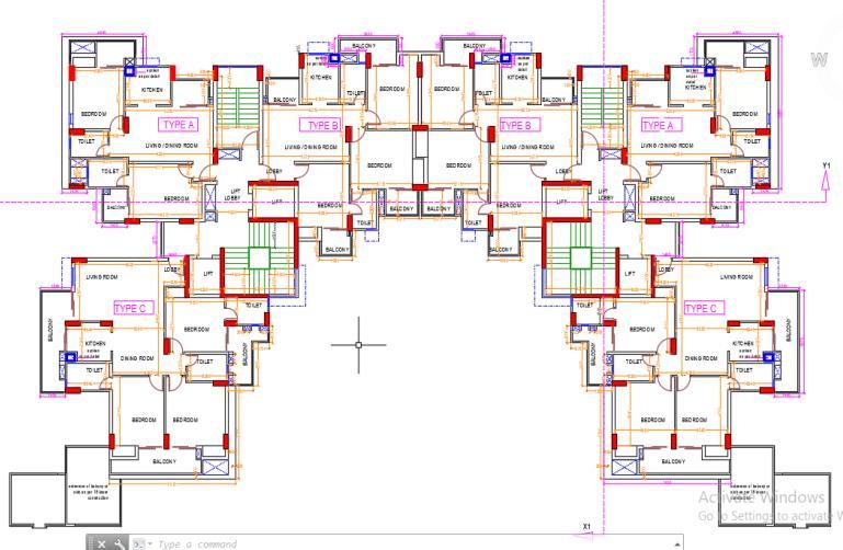
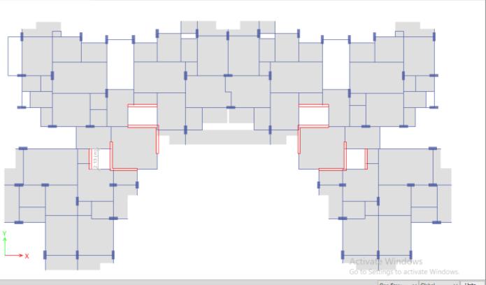
A case study G+19 building has been considered in this research work, which is currently under construction in Noida, Uttar Pradesh. All members that influencethemass,strength,stiffness,anddeformabilityof the structure are included in the building's analytical models.Beams,columns,slabs,walls,andotherstructural membersofthebuilding.Stepbackandstepbacksetback configurations are included to the actual plan of the building in our research. Building is considered resting sloping ground with varying angle of 0°, 15°, 20° and 25° asperthecalculationsshowninfig.2.Floortofloorheight ofthebuildingis3m.Responsereductionfactoristakenas 5forspecialmomentresistingframe.Statictimeperiodof the building is calculated by imperial formula as per IS: 1893:2016. Wind load has been applied as per IS 875 2015. Column and beams sizes are designed in ETABS Software as per the requirement. Wind speed of 44m/s and47 m/shasbeenconsideredandTotal 16modelsare preparedforthecomparison.
The models are prepared in ETABS and initially examined by equivalent static analysis for various slopes, i.e. 0°, 15°, 20° and 25°, and seismic base shear is determined. After this, response spectrum with dynamic scaling, i.e. matching base shear of equivalent static analysis and response spectrum analysis is done as per IS1893:2016. For various slopes, dynamic analysis is performed on step back and step back setback building models. Base shear, story drift, lateral displacement, overturning moment, and building time period are the primaryfactorsconsideredinthisresearchwork.Analysis performed is to check the seismic efficiency of several modelswithdifferentslopes.
The models are prepared in ETABS and initially examined by equivalent static analysis for various slopes, i.e. 0°, 15°, 20° and 25°, and seismic base shear is determined. After this, response spectrum with dynamic scaling, i.e. matching base shear of equivalent static analysis and response spectrum analysis is done as per IS1893:2016. For various slopes, dynamic analysis is performed on step back and step back setback building models. Base shear, story drift, lateral displacement, overturning moment, and building time period are the primaryfactorsconsideredinthisresearchwork.Analysis
performed is to check the seismic efficiency of several modelswithdifferentslopes.
International Research Journal of Engineering and Technology (IRJET) e-ISSN: 2395-0056
Volume: 11 Issue: 05 | May 2024 www.irjet.net p-ISSN: 2395-0072
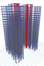
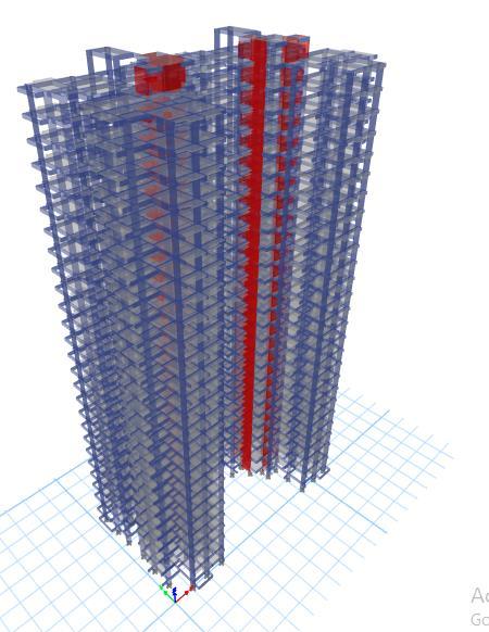
Fig. 7: Buildingwith15degreeslopestepback configurationconsidered
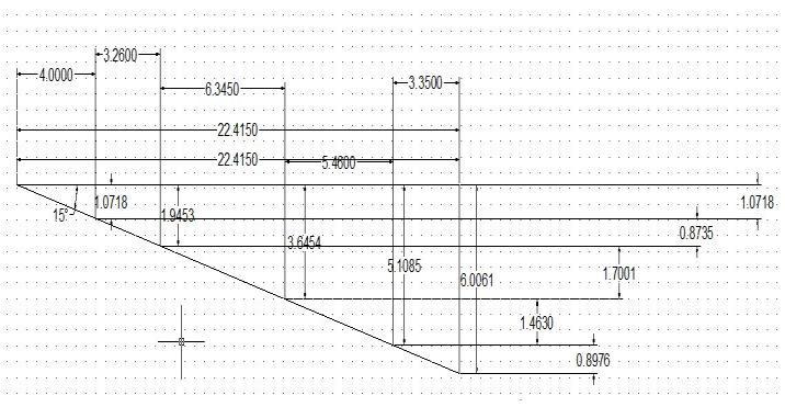
Fig. 6: Buildingon15degreeslope
The evaluation of lateral performance is a complicated process since various elements influence the building's behaviour. The modelsin Chapter 3arefirst examined by equivalent static analysis seismic base shear for various slopes, i.e. 0, 15, 20, and 25, and then by response spectrumwithdynamicscaling,i.e.matchingbaseshearof equivalentstaticanalysisandresponsespectrumanalysis. For various slopes, a dynamic analysis of step back and step back setback building models is performed. Base shear, story drift, lateral displacement, overturning moment, and time period of the building are the primary characteristics evaluated in this study to assess the seismic performance of different models with different slopes. The results are also compared across wind speed
44m/s and 47 m/s for seismic zone II for Pune region. In thischapter,thefindingsoftheanalysisarediscussed.
Chart-1:VariationofbaseshearinX&Ydirectionforbuilding withvaryingslopeangleforwindspeed44m/sforstepback buildingandstepbacksetbackbuilding
Chart-2:VariationofbaseshearinX&Ydirectionforbuilding withvaryingslopeangleforwindspeed47m/sforstepback
Chart-3:VariationofstorydriftinX&Ydirectionforbuilding withvaryingslopeangleforwindspeed44m/sforstepback buildingandstepbacksetbackbuilding
International Research Journal of Engineering and Technology (IRJET) e-ISSN: 2395-0056
Volume: 11 Issue: 05 | May 2024 www.irjet.net p-ISSN: 2395-0072
Chart-4:VariationofstorydriftinX&Ydirectionforbuilding withvaryingslopeangleforwindspeed47m/sforstepback buildingandstepbacksetbackbuilding
Chart-5:VariationofmaximumlateraldisplacementinX&Y directionforbuildingwithvaryingslopeangleforwindspeed44 m/sforstepbackbuildingandstepbacksetback
Chart-7:VariationofTimeperiodofbuildingwithvaryingslope angleforstepbackbuildingandstepbackset
Chart-6:VariationofmaximumlateraldisplacementinX&Y directionforbuildingwithvaryingslopeangleforwindspeed47 m/sforstepbackbuildingandstepbacksetback
Chart-8:Variationofmaximumoverturningmomentforbuilding withvaryingslopeangleinseismiczoneIIforstepbackbuilding andstepbacksetback Chart-9:Variationofmaximumoverturningmomentfor
International Research Journal of Engineering and Technology (IRJET) e-ISSN: 2395-0056
Volume: 11 Issue: 05 | May 2024 www.irjet.net p-ISSN: 2395-0072
Wind loads are calculated as per IS 875 Part 3, which will increase with the slope angle as height of the building increases with increase in slope angle. From results,Slopeofbuildingwasmaintainedbyincreasingthe heightofcolumnsfromonesideascomparedtootherside which creates additional torsional effect on the building. Fromtheresults,itwasfoundoutthatthereisnotmuchof changeinbaseshearduetoslopeofground asonlyslight increase of 0.5-1% in base shear is observed due to sloping ground due to increase in wind loading of the building at sloping part of the structure due to wind loading. From the results, it was also found out that there is significant increase in maximum story drift of the structureduetoslopinggroundi.e.around10-25%.there isadrasticchangeof4-5%isobservedwhenslopeangleis increased from 15° to 20° to 20° to 25°. Also there is reduction in maximum story drift for step back set back configuration as compared to step back configuration by around 10-15% in X direction and almost no change in Y direction dueto wind loading. It was found out thatthere issignificantincreaseinMaximumlateraldisplacementof thestructureduetoslopinggroundi.e.around12-25%in X direction % 10-21% in Y direction. There is increase of around 5-7% in maximum lateral displacement when slope angle changes from 15-20 & 20-25. Also there is reduction in maximum lateral displacement for step back set back configuration as compared to step back configuration by around 10-12% in X direction and increasebyaround8-10%inYdirectionforwindloading. From the results, it was found out that that maximum Overturningmomentofthebuildingisincrease by5-15% for sloping ground as compared to building on plain ground. Again there is increase only 3-5% in overturning moment when slope angle is changes from 15° to 20° & 20-25. There is 6-8% increase is there in maximum overturning moment for step back set back configuration as compared to step back configuration for wind loading. Thus we can summarize that step back set back configurationperformsbetterascomparedtonormalstep back building resting on sloping ground. Over turning moment as well as lateral displacement & drift is significantlylessinstepbacksetbackconfiguration.
1. Manduskar, S. and Shingade, V.S., 2023. Effect of wind on RC structure resting on sloping ground and analysis done using ETABS software. World Journal of Advanced Engineering Technology and Sciences,9(1),pp.193-202.
2. Khan,M.K.S.K.I.andSuthar,M.A.,2023.Analysisof WindLoadEffectsonRCStructureRestingonFlat andSlopingGroundbyUsingE-tabs.
3. Sivanantham, P., Selvan, S.S., Srinivasan, S.K., Gurupatham,B.G.A.andRoy,K.,2023.Influenceof Infill on Reinforced Concrete Frame Resting on Slopes under Lateral Loading. Buildings, 13(2), p.289.
4. Jarapala, R. and Menon, A., 2023. Seismic performance of reinforced concrete buildings on hill slopes: a review. Journal of The Institution of Engineers(India):SeriesA,104(3),pp.721-745.
5. Aggarwal, Y. and Saha, S.K., 2021, December. Seismic performance assessment of reinforced concrete hilly buildings with open story. In Structures(Vol.34,pp.224-238).Elsevier.
6. Daniel,A.J.andSivakamasundari,S.,2016.Seismic vulnerability of building on hill slope. International Journal of Earth Sciences and Engineering,pp.1887-1894.
7. Rathod, H. and Shetty, 2021, T., Effect Of Slope Angel Variation On Tall Structure Resting On SlopingGroundWithSoilStructureInter-Action.
8. Jeong, S.Y., Alinejad, H. and Kang, T.H.K., 2021. Performance-based wind design of high-rise buildings using generated time-history wind loads. Journal of Structural Engineering, 147(9), p.04021134.
9. Stathopoulos,T.andAlrawashdeh,H.,2020.Wind loadsonbuildings:Acodeofpracticeperspective. Journal of Wind Engineering and Industrial Aerodynamics,206,p.104338.
10. Kakde, D.N. and Kasheef, S.M., 2020. Influence of slopeangle variation on the structures resting on Sloping ground subjected to heavy winds. Solid StateTechnology,63(1s),pp.2352-2364.
11. Tak, N., Pal, A. and Choudhary, M., 2020. Analysis of Building with Tower on Sloping Ground. International Journal of Current Engineering and Technology,pp.247-254.
12. Krishnam Raju, P., Ravindra, V. and Susmitha, V., 2019, January. Influence of wind speed on a Reinforced Concrete tall building. In Materials Science and Engineering Conference Series (Vol. 1025,No.1,p.012030).