
Graphene-dye nanocomposite for advanced solar cell applications: Combined experimental and theoretical study
Prosenjit Choudhury1 Md. Nur Alam2 , Ankana Karmakar3, Amitava Mandal4 , Md.Rabiul Islam1*
1Department of Physics, Dr. Meghnad Saha College, Itahar-733128, India,
2Department of Physics, Raiganj University, Raiganj-733134, India
3,4Department of Chemistry, Raiganj University, Raiganj-733134, India
*Corresponding Author Name: Dr. Md.Rabiul Islam ***
Abstract
In this work, a composite system comprised of Methyl Orange dye (MO) and reduced graphene oxide(rGO) system was designed and synthesized. Graphene has been synthesized from graphite flakes by oxidation using improved method. Reduced graphene oxide (rGO) was obtained via simple reduction treatment of GO (graphene oxide) powder. rGO was utilized as non-fullerene acceptor material owing to its lower value of LUMO energy level. Furthermore, its exceptional electron accepting also supported by density functional theory-based calculation. An organic solar cell is fabricated using rGO together with Methyl Orange as standard donor material in ambient atmosphere. Photo response in photoconduction mode have been observed which increases with bias voltage. Investigation of dark I-V characteristics reveals trap charge limited conduction processes within the device. This sort of stable organic material can simply be utilized in fabricating organic solar cell and hence it can be used as one of the best alternatives as non-fullerene acceptor materials.
Keywords
Organic solar cell, graphene-based organic nanomaterials, non-fullerene acceptor, dye-based acceptor at ambient temperature, DSSC, DFT
1. Introduction
Need of the day is environment-friendly renewable energy production because advancement of civilization demands higher energy production. Conventional energy sources are comprised of fossil fuels and nuclear energy sources. Burning of fossil fuels produces green-house gases which in turn are responsible for global climate warming and related catastrophic events likeextremeweatherconditions,meltingoficeinpolarregionetc.Inaddition,theresourcesoffossilfuelsarelimited.Nuclear reactors on the other hand possess the threat of radioactive- wastages. To help avoid these potential threats from conventional energy resources solar cell is the best alternative. Though inorganic solar cells are greatly being used now-adays, but these devices have the disadvantage of high processing cost. Organic photo-voltaic (OPV) emerged in 80’s as a possible replacement. Since the inception, organic solar cells grabbed the eye of scientific community. The primary benefits associated with using organic solar cells (OSC) are simple processing techniques, mechanical flexibility and large stock of materialsthatcanbetailoredtodesiredlevelofbandgaps(heredifferencebetweenLUMOandHOMOlevel)[1-9].Atpresent, theOPVtechnologyisat3rdgeneration.Nowadaysthemostrecentthirdgenerationsolarcellsincludeperovskitesolarcells, polymer based solar cells, dye sensitized solar cells. Among these, the dye sensitized solar cells (DSSCs) has attracted much attentionin worldwidedue toitssimpleprocessingtechniques,flexibilityandlow cost[10].However,thepowerconversion efficiency(PCE)andlong-termoperationalstabilityofDSSCsarenotuptothemark forpracticalapplications,incomparison to traditional silicon-based solar cells. Consequently, tremendous research efforts are going on to realize high performance andsustainabledevicesby introducing novel materialsandnewsynthesis techniques.Asa consequence of theirremarkable optoelectronic, mechanical, thermal, and chemical properties, novel materials, particularly carbon-based ones like graphene anditsderivatives,havethegreatestpossibilitytoreplaceoralterthetraditionalmaterialsthatareoftenusedinthecreation of the various DSSC components. Additionally, the recent use of graphene-based materials as photoanodes transparent conducting anodes, semiconducting layers and dye-sensitizers, electrolytes and counter cathodes in DSSCs [11]. Graphene derivativesfindsitsapplicationmostlyasanodes[12-13]andCathodes[14-17].However,theutilizationissomehowlimited. Graphene may also be utilized as acceptor material [18-20]. For the dye component aromatic azo compound like Methyl
2024, IRJET | Impact Factor value: 8.226 | ISO 9001:2008 Certified Journal | Page871
Volume: 11 Issue: 05 | May 2024 www.irjet.net
orange(MO) isthe attractiveoption duetotheir easy synthesis, high environmental stability and theirtunabilityissues.Azo dyes are well-known photoactive materials owing to their good chemical stability, good optical switching property and high solution process ability [21]. In this context, we have designed, synthesized and characterized a dye based organic solar cell withMethylOrangeandreducedGrapheneOxideblend,asanewphotoactivematerial.ItItpossessesalowerenergeticlowest unoccupied molecular orbital (LUMO) level, stronger electron accepting ability noteworthy solubility in distill water. The photovoltaiccellcomprisesofathinlayerofblendsoforganicdyeMethylOrangeandgrapheneinformofdust(rGO),which servesastheopticalactivematerial.Tocomprehendtheperformanceofthedevice,thedarkI-Vcharacteristicsisexaminedin laboratory. Sampietro et al. illucidates the current voltage characteristics of organic solar cells. They demonstrated the existenceofthreedistinctregimeswithinthecurrentvoltagedependence[22].Itiswellknownthattrapcentersarisingfrom different defects due to structural disarray play a noteworthy role in the current conduction mechanism. These generated traps sates will invite energy levels in between the HOMO-LUMO energy levels providing ease of transport. With increased energy below the LUMO, the dispersion of these trap levels may shrink exponentially. The operation of the device depends heavily on the charging and discharging of these trap levels. The charge transport and semiconducting properties of organic materials are quite different from their traditional inorganic equivalent due to the polymer's crystalline-amorphous nature and the delocalization of the electric field along the π-conjugated segments of the polymer backbone. The I-V characteristics demonstrate that, like other organic material-based devices, the same device is governed by a trap-assisted model. The outcomes have been successfully explained by the assumption that there is an exponential trap distribution [23-24]. Additionally,DFTcalculationshavebeencarriedouttounderstandtheEnergydiagramofthesystem,UVsimulationofMethyl Orangedye,UVdataexcitationenergyanalysis,HOMO-LUMOoftherGO-MethylOrangecomposite.
2. Experimental Section
2.1 Materials and methods:
Thechemicalsusedtopreparethedyebased rGOnanocompositesare(i)`PVAprocuredfromNICECHEMICALS(P)LTD,(ii) MethylOrangedyeprocuredfromLOBACHEMIEPVT LTDand(iii)GraphiteFinePowderprocuredfromLOBA CHEMIEPVT LTD.Allmaterialsareusedasreceivedwithoutfurtherpurification.
2.2 Synthetic procedure of preparation of Graphene Oxide:
Graphite flakes were oxidized using the recent method. 9:1 mixture of concentrated H2SO4/H3PO4 (360:40 mL) was poured intoamixtureofgraphiteflakes(3.0g,1wtequiv)andKMnO4 (18.0g),andexposedto35-40°C.Thereactionwasthenheated to 50 °C and stirred for 12 h. The reaction mixture was then cooled to normal room temperature and kept on ice (400 mL) with30%H2O2 (3mL).Afterthatcentrifugationwasdone(4000rpmfor4h),anddecantationwascarriedout.Theremaining solidmaterialwasthenwashedinsuccessionwith200mLofwater,200mLof30%HCl,and200mLofethanolforeachwash, themixturewassiftedthenfilteredandthefiltratewascentrifuged(4000rpmfor4h)andfollowedbydecantationwasdone The solid obtained by the filtration process was dried in vacuum overnight at room temperature, obtaining 5.8 g of product [25].
2.3
Synthesis of reduced graphene oxide:
Afterachievingtheabovesteps,reducedgrapheneoxide(rGO)wasobtainedviasimplereductiontreatmentofGO(graphene oxide) powder. The GO powder was annealed at various temperatures (200, 300 and 400 oC) in oven. During annealing process Graphene Oxide changed to dark powder as rGO material. The alteration is caused by the decrease of oxygenated functionalgrouponGOsheets[26]
2.4 Computational Methods:
In this study, density functional theory (DFT) was employed using the Gaussian 16 program to perform all theoretical calculations [27]. The ground state geometry optimizations of Methyl Orange (MO), Reduced Graphene Oxide(rGO), and the MO-rGO composite system were conducted at the B3LYP/6-31+G(d) level of theory. The hybrid functional B3LYP offers reliableandpreciseenergyvaluesofnon-covalentlybondedinteractionsforhydrogenbondedandπ–πstackedsystems.The Polarizable Continuum Model (PCM) was applied to introduce solvent effects (water) during the ground state optimization [28].TD-DFTcalculationsareperformedatathesameleveloftheory.Vibrationfrequencyanalysiswasperformedatthesame
Volume: 11 Issue: 05 | May 2024 www.irjet.net
2395-0072
level of theory (no imaginary frequency) and subsequently no imaginary frequency clearly indicates that the geometries correspondstotheminimaatthepotentialenergysurface.ThevisualizationofvariousweakinteractionssuchasH-bonding, van der Waals interactions, and steric interactions was achieved by reduced density gradient (RDG) using the Multiwfn 3.7 suite [29]. The nature of electronic transitions in terms of involved molecular orbitals (MOs) are interpreted by using Gaussum3.0[30-32] Inordertoassessthedegreeofcharge-transferinteractionswithintheMethylOrange-reducedgraphene oxidecomplexsysteminawatermedium,molecularelectrostaticpotential(MESP)mapswerecreatedusingthesamelevelof theory.Theadsorptionenergies( ofthecomplexsystemweredeterminedusingthefollowingequation.
Where, are the total energy of the geometry optimized complex system, reduced graphene oxide and the methylorangedyerespectively.
2.5 Device fabrication:
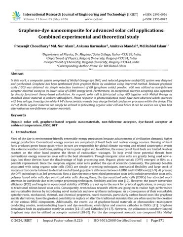
Deyetal.fabricatedaphotovoltaiccellbysandwichinganorganicphotoactivematerialbetweentwoelectrodes[33].Wehave followedthesimilartechniquefordevicefabrication. Intheresearchdescribedhere,thephotovoltaiccellismadeupofathin layerofblendsoforganicdyeMethylOrange,andgrapheneinformofdust(rGO),whichservesastheopticalactivematerial. Thismixtureservesastheactivematerialinthecellintheformofathinfilm.OnetransparentglassplatecoatedIndium-TinOxide(ITO)servesasthecontactelectrode,andtheothercontactelectrodeismadeofaluminum.MethylOrangedyeismixed withpolyvinylalcohol(PVA).AfterthatPVAsolutionisdonebymixing1gmofPVAwith20mlofdistilledwaterinatesttube, followed by warming and stirring gently. 1 mg of graphene is mixed with this solution. PVA is utilized here as an inert transparent binder to form stable film of the dye. The mixture is stirred and heated to a temperature of 80◦C for 2h. The viscoussolutionissandwichedbetweentransparentITO-coatedglassandaluminumplate.BoththeITOcoatedglassplateand aluminumplatewerecleanedinalcoholsolutionanddriedforapprox1hbeforeuse.Thetwoelectricalleadsaretakenoutof thetwoendsof theelectrodes.Theentirecellisvacuumdriedforabout12houraround60◦Cbeforethefinalmeasurement.
2.6 Experimental setup:
As seen in Figure 1, the PV cell is biased using a d.c. source (making the ITO contact the anode and the aluminum plate cathode).AMastechMAS830Lmultimeterisusedtomeasurethevoltageacrossa33KΩresistancetodeterminethecurrent flowingthroughthedevice.
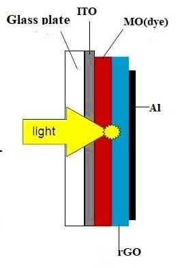
Fig- 1. Structureofthephotovoltaiccell.AthinfilmofblendmadeofMethylOrange,complexedwithPVAanddustof graphene,issandwichedbetweenoneITOcoatedglassplateandaluminumplate.(Thedcsourceandexternalresistanceisnot showninthisfigure)
Volume: 11 Issue: 05 | May 2024 www.irjet.net
2395-0072
Inordertoobtainthedark,I-Vcharacteristics,thebiasvoltageisincreasedfrom0voltto5volts.Thestepofincrementis0.2voltupto3voltandthesameis0.5voltafterthat.Thecurrentisfoundinmicroampererange.Thisrangeofoutputcurrentis quitebeneficial forsolarcell applicationsbecauseitdeterminestheamountof powerthatcanbegeneratedfromthedevice. The higher the current higher will be the power as well as the efficiency of the device. However, the current is seen to be dependingonvariousfactorssuchasmaterialthicknessandmorphology. Afterapplyingeachbiasvoltage,itisseenthatthe current takes some time (a couple of minutes) to attain its steady-state value. For both forward and reverse bias, the I-V properties are roughly symmetric about the origin. For measurement of photocurrent, a tungsten lamp of 100 watt was illuminatedandlightwasallowedtoenterthecellthroughITOcoatedglassplate.Thebiasvoltageisincreasedto0.5to3 volts withastepof0.5volt.Ateachbiasvoltagethevariationofphotocurrentwithtimeisrecorded.
3. Results and discussion
3.1 Experimental Findings
3.1.1 Dark I-V characteristics:
ThedataofappliedbiasvoltageandcorrespondingmeasuredcurrentsareplottedandthecorrespondinglogV-logIarealso obtained by using OriginPro software (shown in figure 2). The log V-log I Plot shown in depicts a transition point at a bias voltage of roughly 1.2 volt, indicating a shift in the conduction mechanism at this bias voltage. By utilizing [2] the relation ,wecalculate =1.2eV(whereas,theoreticallyitwasfoundtobe1.03eV)
TheI–Vrelationshowninthefigurebelowcanbewrittenas,
0.487 for V<1.2V ∝ 1.53 for1.2V<V<5V


Fig Vcharacteristicsofthephotovoltaiccell(left)anditslog-logplot(right)

To analyze the dark,I-V characteristics, the following model for conduction mechanism may be approximated. The lowest unoccupied molecular orbital (LUMO) states, which are like conduction band, and the highest occupied molecular orbital (HOMO) states, which are just like the top of the valence band, are possible places for carriers to be transported during conductionwithinthedevice,Asdocumented intheliterature[18-20].A model basedontrap chargesthatare stateshaving energiesinbetweenHOMOandLUMOlevelistakenintoconsiderationtoexplainthemodificationoftheconductionprocess.
One-dimensionalsingle(double)carrierdriftcurrentandPoissonequations(forelectrons,holes,orboth)serveasthestarting equations,
WhereJisthecurrentdensity,µisthecarriermobility,Eistheelectricfieldstrength,nand arethefreeandtrappedcharge concentrations respectively, e is the unit charge and ϵ is equal to , with being the permittivity of vacuum and k the relative dielectric constant. When traps have an exponential energy distribution, the trap charge concentration ( ) is given by, (3)
Where , is the trap density, �� is the electron fermi energy, is the Boltzmann’s constant and ���� is the characteristic temperature of the exponential trap distribution (i.e., ����= ��/ ��, where ��is the characteristic trap energy). Solving Equations (1)and(2)withtheabovedistributionoftrapsthecurrent-voltage(J-V)characteristicshastheform[21]:
=����μ(1−��){����/�� (��+1)}
Wherem=��/T.ThemostnotablefeatureinEquation(4)isthepower-lawdependence–Vm+1 .
(4)
FittingtheexperimentaldataforthedarkI-Vcurve,asshownfigure2andwiththehelpofequation(4),wefindthatabovethe voltage1.2volt,thecurrentvoltageisfitted usingthetrapchargelimitedmodelandthevalueofmisequalto 0.53andhence �� iscalculatedtobe159Kand iscalculatedtobe0.013eV.
3.1.2 Photocurrent

Biasvoltage=3.0V
Biasvoltage=2.5V
Biasvoltage=2.0V
Biasvoltage=1.5V
Biasvoltage=1.0V
Biasvoltage=0.5V
The photo current for this graphene oxide dye based solar cell (in photo-conducting mode) is measured with a Mastech MAS830Lmultimeterandphotocurrentisplottedwithtimeaccordinglyasshowninthefigure3above.Thephotocurrentis foundto beinmicroampererange.Itisalsofoundthat thephotocurrentincreases withtheincreaseinvoltage.Theoretical analysisof|thephoto-currentdataisnotdoneherebutacomparisonofthevalueofphotocurrentwithandwithoutgraphene showstheenhancedeffectasaresultofincorporationofgrapheneinmethylorangedyebasedcompositefilm.
3.2 Theoretical studies
In order to interpret the experimental findings, we choose model rGO system to develop nanocomposite with MO dye as showninthefigure4whererGOservesasanacceptormaterialandMOdyeservesasadonormaterial.Groundstategeometry optimization of the donor and acceptor nanocomposite revealed that rGO and MO dye is strongly interacted by shorter H bondsrangingfrom2.22Åto2.80Åyieldingahighadsorptionenergyof-6.02eV.
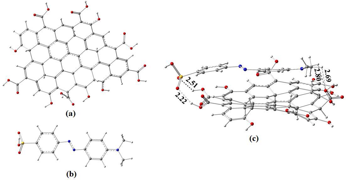
Fig-4. Groundstateoptimizedstructureof(a)ReducedGrapheneOxide(b)MethylOrange(c)MO-rGOcompositesystemRed, gray,white,andbluecolorrepresentsoxygen,carbon,hydrogen,andnitrogenatomsrespectively.
To analyze the excited state of the MO dye alongside the nanocomposite time dependent DFT(TD-DFT) were employed accounting all singlet excitation at the same level of theory. Excited state properties such as vertical excitation energies and oscillatorstrengthsarecomputedfromsinglepointenergycalculationsoftheexcitedstateandtabulatedintheTable1aand 1b.
Table-1a Computedabsorptionwavelengths( innm),verticalexcitationenergies( ineV),oscillatorstrengths(f),the compositionofthecorrespondingelectronictransitions(H,HOMO;L,LUMO),calculatedinwaterbyusingB3LYP/6–31+G(d) leveloftheoryMOdye
Table-1b Computedabsorptionwavelengths( innm),verticalexcitationenergies( ineV),oscillatorstrengths(f), thecompositionofthecorrespondingelectronictransitions(H,HOMO;L,LUMO),calculatedinwaterbyusingB3LYP/6–31+G(d)leveloftheorynanocomposites.
Volume: 11 Issue: 05 | May 2024 www.irjet.net p-ISSN:2395-0072
To comprehend the electron excitation process involving the reduced graphene oxide and methyl orange nanocomposite systemenergybandalignmentsomeselectedorbitalsthatdeterminetheelectroninjectionprocessofthedyeviz.HOMOand LUMOenergylevelsoftheindividualcomponentsalongwiththeelectrodesareanalyzedasshowninthefigure5.

5. BandalignmentofrGO,MOdyeinwater
This scenario inevitably ensures the possibility of a photo-induced intramolecular charge transfer along the p-conjugated skeletonandfinallyelectroninjectionfromthedyetotheconductionbandofrGO.
With a view to gain insight into the light harvesting and optical properties of the MO dye, UV- spectra and corresponding absorptiondata arecollectedintable1.FromUVspectra analysisitisfoundthattheabsorptionpeak isat461.56nmwhich wascontributedbyHOMO->LUMOtransition.ThisvalueisconcordedwiththevalueofabsorptionpeakofMOdyeinaqueous solution which is found to be 463 nm [34]. Another peak occurs at 284.52 nm which was contributed by HOMO-4-> LUMO transition. The oscillator strengths corresponding to the peaks are 1.151 and 0.215 respectively. The oscillator strength is proportional to the intensity incident upon the dye. The amount of absorption increases with increasing value of oscillator strength. From the spectra it is evident that the dye (donor) absorbs light in the visible range and corresponding exited electronsaretransferredtotherGO(acceptor).Hencethecompositesystemcanbeusedasadyesensitizedsolarcell.
OnanalyzingtheUV-spectraandcorrespondingabsorptiondataofrGO-MOcompositesystem,wefoundanabsorptionpeakat 563.97 nm which extends over the infrared region ensuring the composite system is capable of harvesting the entire solar spectra as shown in figure 6. Compared to the peak of MO dye, the former is well inside the visible region. So, the rGO-MO compositesystemisapromisingcandidateforfaithfulphotovoltaicapplications.

Fig- 6. SimulatedUV-visabsorptionspectraforMOdyeandCompositesystem
Fig-
Volume: 11 Issue: 05 | May 2024
www.irjet.net p-ISSN:2395-0072
We have even analyzed the electrostatic potential map of the composite system and found that enhanced electrostatic interactionbetweentherGOandMOexist(redregionoftheESPmap)asshowninthefigure7.

To learn about the type of interactions between dye and clusters (Van der Waals interactions, steric interactions), noncovalentinteraction(NCI)indexplotsofthereduceddensitygradient(RDGors)vs.moleculardensityρwereanalyzedusing the Multiwfn 3.7 suite. To identify the attractive and repulsive interactions, the eigenvalues (λi) of the second derivative of densityareplottedwithintheframeworkofthenon-covalentindextechnique.Thestabilizinginteractionsaredesignatedby negative values, while repulsive interactions are categorized by positive values of sign(λ2)ρ. NCI-RDG plots for MO-rGO compositesystemisshowninthefigure8

Fig- 7.ElectrostaticpotentialmapofrGO-MOcompositesystem
Fig- 8.RDGplotsofMO-rGOcompositesystem
Volume: 11 Issue: 05 | May 2024 www.irjet.net
p-ISSN:2395-0072
Intheplot,theblueregionindicatesVanderwallsinteractionswhiletheredandgreenregionsindicatestrongattractionand steric repulsion respectively. It is clear from the plot that in the composite system taken, Van der walls interactions are prominentattheMO-rGOinterface.
4. CONCLUSION
To summarize, graphene dye-based device has been designed and synthesized and was explored as non-fullerene acceptor nanomaterials.Fabricationofanorganicsolarcellbyuseofthisstableacceptorwasperformedwithinambientatmosphere. Simulation of the device reveals that reduced graphene oxide and methyl orange makes a highly interacting nanocomposite system via shorter H bonding. Furthermore, DFT calculations also indicate the acceptable energy alignment and excellent acceptor capability for its| application in photovoltaic devices. TDDFT calculation reveal that when compared to MO dye the compositesystemisquitecapableabsorbingthewholeradiationofthesolarspectrum.Itisevidentformtheenergyalignment that this composite is suitable for flow of electron. Formation of nanocomposite formations via H bonding, appropriate alignmentforelectrontransfer ensuresa gooddeviceformation.Experimentally,theenhancementofphotoconductivityasa result of incorporation of graphene in dye based PVA film were found. Study of the device's steady-state dark I-V characteristics explores the nature| of trap distribution because current conduction generally in most organic materials is controlled by trap distribution. Experimentally, we have found that above a threshold voltage of 1.2 volt, the conduction is organizedbyanexponentialdistributionoftrapcentres.Becausethetransitioninoursystemisspreadratherthanabrupt,the traplevelsarenotconcentratedinasingleenergylevel.Withintheexperimentalbounds,ithasbeenestimatedthatonetrap's temperatureandenergylevelare,respectively,159Kand0.013eV.Studyingthesteady-stateoperationofasolarcellbasedon graphenedyenanocompositewillbemadesimplerwiththeusetheexperimentaldata.
Acknowledgement
We wish to acknowledge especially Prof. Kumaresh Ghosh, Department of Chemistry, University of Kalyani for supporting theoreticalcalculations.
References:
1. Gan, Q., Bartoli, F. J., &Kafafi, Z. H. (2013). Plasmonic‐enhanced organic photovoltaics: Breaking the 10% efficiency barrier. Advanced materials, 25(17),2385-2396.
2. Pei,Q.(1996).Yang;Yu,G.;Zhang,C.;Heeger.J.Am.Chem.Soc,118,3922.
3. Green,M.A.,Emery,K.,Hishikawa,Y.,&Warta,W.(2008).SolarCellEfficiencyTables,Prog.Photovolt. Res. Appl, 16,61.
4. Bauhuis,G.J.,Mulder,P.,Haverkamp,E.J.,Huijben,J.C.C.M.,&Schermer,J.J.(2009).26.1%thin-filmGaAssolarcellusing epitaxiallift-off. Solar Energy Materials and Solar Cells, 93(9),1488-1491.
5. Solar PV Manufacturing Cost Analysis. Available online: http://www.nrel.gov/analysis/key_activities_jobs_pv_mfg_cost.html(accessedon10October2011).
6. Kumar,P.,&Chand,S.(2012).Recentprogressandfutureaspectsoforganicsolarcells. Progress in Photovoltaics: Research and applications, 20(4),377-415.
7. Dou, L., You, J., Hong, Z., Xu, Z., Li, G., Street, R. A., & Yang, Y. (2013). 25th anniversary article: a decade of organic/polymericphotovoltaicresearch. Advanced materials, 25(46),6642-6671.
8. Zhou,N.,Buchholz,D.B.,Zhu,G.,Yu,X.,Lin,H.,Facchetti,A.,...&Chang,R.P.(2014).Ultraflexiblepolymersolarcellsusing amorphouszinc−indium−tinoxidetransparentelectrodes. Advanced Materials, 26(7),1098-1104.
9. Tang,C.W.(1986).Two‐layerorganicphotovoltaiccell. Applied physics letters, 48(2),183-185.
Volume: 11 Issue: 05 | May 2024 www.irjet.net p-ISSN:2395-0072
10. Rathore,N., Panwar,N.L., Yettou, F.,&Gama,A. (2021). Acomprehensive reviewof differenttypesof solarphotovoltaic cellsandtheirapplications. International Journal of Ambient Energy, 42(10),1200-1217.
11. Muchuweni,E.,Martincigh,B.S.,&Nyamori,V.O.(2020).Recentadvancesingraphene-basedmaterialsfordye-sensitized solarcellfabrication. RSC advances, 10(72),44453-44469.
12. Manzano-Ramírez,A.,López-Naranjo,E.J.,Soboyejo, W., Meas-Vong,Y.,&Vilquin,B.(2015).Areviewonthe efficiencyof graphene-basedBHJorganicsolarcells. Journal of Nanomaterials, 2015
13. Xu, Y., Long, G., Huang, L., Huang, Y., Wan, X., Ma, Y., & Chen, Y. (2010). Polymer photovoltaic devices with transparent grapheneelectrodesproducedbyspin-casting. Carbon, 48(11),3308-3311.
14. Gao,X.,Ma,W.,Han,G.,Chang,Y.,Zhang,Y.,&Li,H.(2019).Theelectrochemicalpropertiesofreducedgrapheneoxidefilm with capsular pores prepared by using oxalic acid as template. International Journal of Energy Research, 43(14), 81778189
15. Jung,S.,Lee,J.,Choi,Y.,Lee,S.M.,Yang,C.,&Park,H.(2017).Improvedinterfacecontrolforhigh-performancegraphenebasedorganicsolarcells. 2D Materials, 4(4),045004.
16. Jung, S., Lee, J., Seo, J., Kim, U., Choi, Y., & Park, H. (2018). Development of annealing-free, solution-processable inverted organicsolarcellswithN-dopedgrapheneelectrodesusingzincoxidenanoparticles. Nano letters, 18(2),1337-1343.
17. Kim,H.,Byun,J.,Bae,S.H.,Ahmed,T.,Zhu,J.X.,Kwon,S.J.,...&Lee,T.W.(2016).On‐FabricationSolid‐StateN‐Dopingof Graphene by an Electron‐Transporting Metal Oxide Layer for Efficient Inverted Organic Solar Cells. Advanced Energy Materials, 6(12),1600172.
18. Jo, G., Na, S. I., Oh, S. H., Lee, S., Kim, T. S., Wang, G., ... & Lee, T. (2010). Tuning of a graphene-electrode work function to enhance the efficiency of organic bulk heterojunction photovoltaic cells with an inverted structure. Applied Physics Letters, 97(21),253.
19. Liu,Q., Liu,Z.,Zhang, X.,Zhang,N., Yang, L., Yin, S., & Chen, Y. (2008). Organic photovoltaiccellsbased on an acceptor of solublegraphene. Applied Physics Letters, 92(22),195.
20. Yu, D., Park, K., Durstock, M., & Dai, L. (2011). Fullerene-grafted graphene for efficient bulk heterojunction polymer photovoltaicdevices. The Journal of Physical Chemistry Letters, 2(10),1113-1118
21. Farag,A.A.M.,Mansour,A.M.,Ammar,A.H.,&Rafea,M.A.(2011).Characterizationofelectricalandopticalabsorptionof organicbasedmethylorangeforphotovoltaicapplication.SyntheticMetals,161(19-20),2135-2143
22. M.SAMPIERTO,R.SOTGIU,F.P.WENZL,L.HOLZER,S.TASCHandG.LEISING, ibid. 61 (2000)266
23. Burrows, P. E., Shen, Z., Bulovic, V., McCarty, D. M., Forrest, S. R., Cronin, J. A., & Thompson, M. E. (1996). Relationship between electroluminescence and current transport in organic heterojunction light‐emitting devices. Journal of Applied Physics, 79(10),7991-8006
24. Yang, J., & Shen, J. (1999). Effects of discrete trap levels on organic light emitting diodes. Journal of appliedphysics, 85(5),2699-2705.
25. Marcano,D.C.,Kosynkin,D.V.,Berlin,J.M.,Sinitskii,A.,Sun,Z.,Slesarev,A.,...&Tour,J.M.(2010).Improvedsynthesisof grapheneoxide. ACS nano, 4(8),4806-4814.
26. Zainuddin, M. F., Raikhan, N. N., Othman, N. H., & Abdullah, W. F. H. (2018, May). Synthesis of reduced Graphene Oxide (rGO)usingdifferenttreatmentsofGrapheneOxide(GO).In IOP Conference Series: Materials Science and Engineering (Vol. 358,No.1,p.012046).IOPPublishing
Volume: 11 Issue: 05 | May 2024 www.irjet.net p-ISSN:2395-0072
27. Frisch,M.;Trucks,G.;Schlegel,H.;Scuseria,G.;Robb,M.; Cheeseman, J.; Scalmani,G.;Barone,V.; Petersson,G.;Nakatsuji, H.,Gaussian16.Gaussian,Inc.Wallingford,CT:2016.
28. Cossi,M.;Barone,V.;Cammi,R.;Tomasi,J.,Abinitiostudyofsolvatedmolecules:anewimplementationofthepolarizable continuummodel. Chemical Physics Letters 1996, 255 (4-6),327-335.
29. Lu,T.;Chen,F.,Multiwfn:amultifunctionalwavefunctionanalyzer. Journal of computational chemistry 2012, 33 (5),580592.
30. Zhao,Y.,& Truhlar,D.G. (2008).TheM06 suite of densityfunctionalsformain groupthermochemistry, thermochemical kinetics, noncovalent interactions, excited states, and transition elements: two new functionals and systematic testing of fourM06-classfunctionalsand12otherfunctionals. Theoretical chemistry accounts, 120,215-241.
31. Miertuš,S.,Scrocco,E.,&Tomasi,J.(1981).Electrostaticinteractionofasolutewithacontinuum.Adirectutilizaionof AB initiomolecularpotentialsfortheprevisionofsolventeffects. Chemical Physics, 55(1),117-129.
32. O'boyle, N. M., Tenderholt, A. L., & Langner, K. M. (2008). Cclib: a library for package‐independent computational chemistryalgorithms. Journal of computational chemistry, 29(5),839-845.
33. Dey, S. K., Islam, M. R., Manik, N. B., & Basu, A. N. (2002). Study of the effect of trap levels on steady-state dark I–V characteristicsinSafranine-T-basedsolid-statethinfilmphotoelectrochemicalcell. Journal of Materials Science: Materials in Electronics, 13,249-252.
34. Chen, Y. P., Liu, S. Y., Yu, H. Q., Yin, H., & Li, Q. R. (2008). Radiation-induced degradation of methyl orange in aqueous solutions. Chemosphere, 72(4),532-536.