
International Research Journal of Engineering and Technology (IRJET) e-ISSN: 2395-0056
Volume: 11 Issue: 04 | Apr 2024 www.irjet.net p-ISSN: 2395-0072

International Research Journal of Engineering and Technology (IRJET) e-ISSN: 2395-0056
Volume: 11 Issue: 04 | Apr 2024 www.irjet.net p-ISSN: 2395-0072
Dr. RA.B. Depaa1*; K. Ganesh babu2; A. Selvakumar3; S. Sudhanraj4; P. Vinayagamani5; Dr. P. Gomathi nagajothi6;
Department of Civil Engineering, Dr. M.G.R. Educational and Research Institute, Chennai - 600095, Tamil Nadu, India
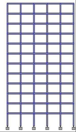
Abstract - Structural engineers are facing new challenges in designing safe structures due to the increase in terrorist actions carried out on landmark buildings which has the potential to cause great destruction, damage, and danger to people. As designers, Engineers are tasked with understanding all the possible loads that a building may encounter in its life and ensuring that the structural system will remain standing and ensure the safety of those inside. An abnormal loading in the past were never considered during design, but an alarming string of events, mostly terrorist, have awakened the need for special considerations for potential targeted buildings. It is virtually impossible to predict what exact extreme load may be induced on a building, therefore when designing for structural integrity the most important consideration is progressive collapse.
A building undergoes progressive collapse when a primary structural element fails, resulting in the failure of adjoining structural elements, which in turn causes further structural failure. Several examples will be given of progressive collapses that occurred in structures due to abnormal loading. Such a failure is catastrophic as collapse occurs in an instance, not allowing time for inhabitants to escape. There are certain details regarding design and retrofit of structures to resist progressive collapse that should be followed, especially for materials such as concrete and steel. In this thesis we have done structural modelling, analysis and design a structure against the progressive collapse.
Keywords: RCC,Progressivecollapse,Modeling,Analysis, DesignandSTAADPro
Structuralengineersarefacingnewchallengesindesigning safe structures due to the increase in terrorist actions carriedoutonlandmarkbuildingswhichhasthepotential to cause great destruction,damage, and danger to people. Asdesigners,Engineersaretaskedwithunderstandingall thepossibleloadsthatabuildingmayencounterinitslife andensuringthatthestructuralsystemwillremainstanding andensurethesafetyofthoseinside.
Abnormalloadingsinthepastwereneverconsideredduring design, but an alarming string of events, mostly terrorist, have awakened the need for special considerations for
potential targeted buildings. It is virtually impossible to predict what exact extreme load may be induced on a building,thereforewhendesigningforstructuralintegrity the most important consideration is progressive collapse. Progressive collapse results when a localized failure spreads to a largerportionofthestructure.
Severalexampleswillbegivenofprogressivecollapsesthat occurred in structures due to abnormal loading. Such a failureiscatastrophicascollapseoccursinaninstance,not allowingtimeforinhabitants to escape. There are certain detailsregardingdesignandretrofitofstructures to resist progressive collapsethatshouldbefollowed,especiallyfor materialssuchasconcreteandsteel.
As a result of increasing catastrophic events in recent years,thepreventionofprogressivecollapseisbecominga requirement in building design and analysis. Many approaches have been proposed to minimize the risk of progressivecollapsein newandexistingbuildings.Amonga numberofbuildingcodes,standards,anddesignguidelines for progressive collapse, General Services Administration (GSA, 2003) and Department of Defense (DoD, 2005) address progressive collapse mitigation explicitly. They providequantifiableandenforceable procedures to resist progressivecollapse.
Wood, C., Lodhi, M., and Sezen, H. - Their paper of this research is to better understand progressive collapse mechanisms of buildings, and to evaluate the current modelling and analysis techniques and design methodologies.Fieldexperimentsandnumericalsimulations were performed to investigate the progressive collapse potential of several reinforced concrete and steel frame buildings. Up to four first-story columns were physically removed from thebuildings to understand thesubsequent loadredistributionwithineachbuilding.Experimentaldata from the field tests were used to compare and verify the computational models and analysis results. Due to the scarcityofdatafromfull-scaletests,theexperimentaldataof thisresearchisavaluableadditiontothestateofknowledge onprogressivecollapseofbuildings.Thedesignguidelines typically recommend simplified analysis procedures involvinginstantaneousremovalofspecifiedcriticalcolumns inabuilding.Thisresearchinvestigatestheeffectivenessof
International Research Journal of Engineering and Technology (IRJET) e-ISSN: 2395-0056
Volume: 11 Issue: 04 | Apr 2024 www.irjet.net p-ISSN: 2395-0072
such commonly used progressive collapse evaluation and design methodologies through numerical simulation and experimentaldata.
Haberland, M. and Starossek, U - Their paper presents Structuralrobustnessisrecognizedasadesirablepropertyof structural systems which mitigates their susceptibility to progressivecollapse.However,thereissomeconfusioninthe literature regarding the usage of the terms structural robustness and collapseresistance as well as competing expressions such as prescriptive vs. performance-based, threat-specific vs.threat-independentorindirectvs.direct design.Thisarticletriestodistinguishbetween thedifferent meanings ofthese fourpairsofterms,whichareimportant conceptsinthefieldofprogressivecollapse.Inthiscontext, design strategies and associated methods to prevent progressivecollapsearebrieflyexplained.
Kirkpatrick,S.,MacNeill,R.,Smith,J.,Herrle,K.,andErekson, M - Existing building codes contain some guidance on progressivecollapseanalysisanddesign.Unfortunately,in mostoftheU.S.buildingcodes and standards that contain progressive collapse provisions, the available guidance is eithervague,ordoesnotdefine,thekeyissuesthatmustbe addressed.Thislackofguidancehasresultedinconflicting interpretationsastohowoneshouldapproachprogressive collapse analysis and design. The General Services Administration (GSA) and Department of Defence Unified FacilitiesCriteria(UFC)ProgressiveCollapseGuidelines[1–3] arecurrentlythemostcompletesetsofcriteriaintermsof providing usable guidance to the designer. However, only through experience can one identify the most appropriate modellingtechniqueforaparticularapplication.
Stylianidis,P.,Nethercot,D.,Izzuddin,B.,andElghazouli,ARecentstudiesofprogressivecollapsehavesoughttomove the design basis from one of the simple following of prescriptive requirements to approaches based on understanding,modellingandquantitativeassessment.Akey requirement for such approaches is the definition of a suitablefailurecriterion expressedbothinphysicalterms andinawaythataccordwithtraditionalviewsofstructural analysis and design. The method developed at Imperial CollegeLondoncheckstheabilityofthedamagedstructureto attainanewequilibriumstateexpressedintermsofavailable connection rotation capacity. The effects of variations in connection type (and therefore properties) in improving resistancetoprogressivecollapsemaythereforebeexamined explicitlyandquantitatively.
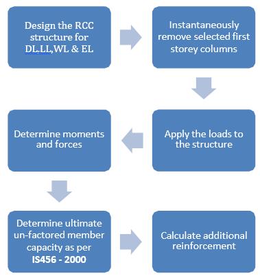
3. Design approach (Alternative Path Method):
In alternate path (AP) method, the design allows local failure to occur, but seeks to prevent major collapse by providing alternate load paths. Failure in a structural memberdramaticallychangesloadpathbytransferringloads tothemembersadjacenttothefailedmember.Iftheadjacent members have sufficient capacity and ductility, the structuralsystem develops alternate load paths.Using this method, a building is analyzed for the potential of progressive collapse by instantly removing one or several loadbearingelementsfromthebuilding,andbyevaluating the capability of the remaining structure to prevent subsequentdamage.
The advantage of this method isthatitisindependentof theinitiatingload,sothatthesolutionmaybevalidforany typeofthehazardcausingmemberloss.Thealternateload pathmethodisprimarilyrecommended in the current building design codes and standards in the U.S., including General Services Administration (GSA, 2003) and the DepartmentofDefense (DoD, 2005) guidelines. Thus,this researchalsofocusesprimarilyontheAPmethodandusedit forprogressivecollapseanalysis.
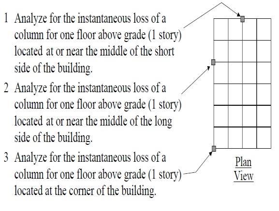
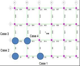
4. Column removal procedure:
Forprogressivecollapseanalysis,GSAmandatesseveral columnlossscenariosasshowninfigure.TheGSAguidelines require removal of first-storey columns. To determine the potential of progressive collapse for a typical structure, designers can perform structural analyses in which the
International Research Journal of Engineering and Technology (IRJET) e-ISSN: 2395-0056
Volume: 11 Issue: 04 | Apr 2024 www.irjet.net p-ISSN: 2395-0072
instantaneouslossofoneofthefollowingfirstfloorcolumns atatimeisassumed:
• Anexteriorcolumnnearthemiddleofthelongside ofthebuilding.
• Anexteriorcolumnnearthemiddleoftheshortside ofthebuilding.
• Acolumnlocatedatthecornerofthebuilding.
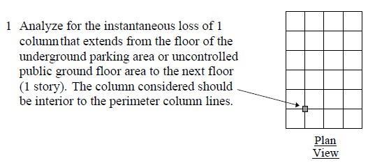
• Acolumninteriortotheperimetercolumnlinesfor facilities that have underground parking or public ground floorareas.
5. Load calculation:
Loadcalculation:DeadLoad SuperImposedDeadLoads(SDL):
FloorFinishes =1.00kN/m2
Partitionsload =0.50kN/m2
Totalloads =1.50kN/m2
WallLoadinBeams =0.23x3.00x20 =13.80kN/m
WallLoadinTerrace =0.23x1x20 =4.60kN/m
LiveLoad
Liveloadatfloorlevels=4.0kN/m2
LiveloadatTerracelevel=5.0kN/m2
Seismicload
International Research Journal of Engineering and Technology (IRJET) e-ISSN: 2395-0056
Volume: 11 Issue: 04 | Apr 2024 www.irjet.net p-ISSN: 2395-0072
ThefollowingSeismicparametersweretakeninaccordance withIS:1893–2002.Fordesignconsiderationthebuilding issituatedZoneIIIandmediumsoillocation
6. Beam design from STAAD Pro:
WidthofBeam = 400mm
DepthofBeam = 600mm
LengthoftheBeam = 6000mm
Concretegrade = M25
Steelgrade = Fe415
Main reinforcement:
Provide3nosofbars#25atthebothfaceofspansection.
Shear reinforcement:
Provide 8mm bars @ 2 legged verticalstirrupsat200mm c/c
7. Column design from STAAD Pro
WidthofColumn=700mm
DepthofColumn=700mm
Concretegrade =M25
Steelgrade =Fe415
Main reinforcement: Provide32nos.of25mmbars
Lateral reinforcement:
Provide8mm#300mmc/caslateralties
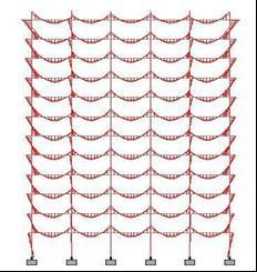
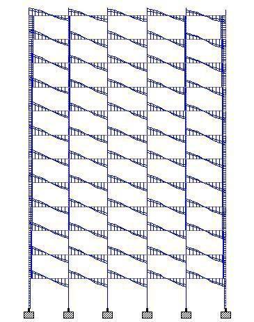
8. Progressive Collapse Analysis & results:
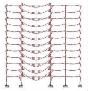
Following the design of thebuildingfor Gravity and Seismic loads,firststoreycolumnswereremovedateachof thefour locationsofthebuildingsasspecified by the GSA criteria. The specified GSA load combination was applied and the demand forces were calculated for each member again usingtheSTAADprogram.
6:ProgressiveAnalysis&DesignresultsfromSTAAD Pro(Case1):
International Research Journal of Engineering and Technology (IRJET) e-ISSN: 2395-0056
Volume: 11 Issue: 04 | Apr 2024 www.irjet.net p-ISSN: 2395-0072
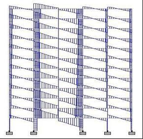
Fig7:BeamdesignfromSTAADPro
WidthofBeam = 400mm
DepthofBeam = 700mm
LengthoftheBeam=12000mm
Concretegrade=M30
Steelgrade =Fe415
Mainreinforcement:
Provide3nosofbars#32atthebothfaceofspansection.
Shearreinforcement:
Provide 8mm bars @ 2 legged verticalstirrupsat220mm c/c
Column design from STAAD Pro:
WidthofColumn = 700mm
DepthofColumn = 700mm
Concretegrade
Concretegrade=M30
Steelgrade =Fe415
Mainreinforcement:
Provide36nos.of25mmbars
Lateralreinforcement:
Provide8mm#300mmc/caslateralties
10. Progressive Analysis & Design results from STAAD Pro (Case 2)
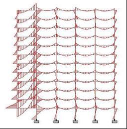
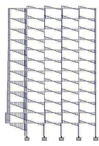
Fig8:BeamdesignfromSTAADPro
WidthofBeam=400mm
DepthofBeam=700mm
LengthoftheBeam=6000mm
Concretegrade=M30 Steelgrade =Fe415
Main reinforcement:
Provide6nosofbars#32atthebothfaceofspan section.
Shear reinforcement:
Provide8mm bars @ 2 legged verticalstirrupsat 120mmc/c
International Research Journal of Engineering and Technology (IRJET) e-ISSN: 2395-0056
Volume: 11 Issue: 04 | Apr 2024 www.irjet.net p-ISSN: 2395-0072
11. Column design from STAAD Pro:
WidthofColumn = 700mm
DepthofColumn = 700mm
Concretegrade
Concretegrade=M30
Steelgrade =Fe415
Main reinforcement:
Provide28nos.of25mmbars
Lateral reinforcement:
Provide8mm#300mmc/caslateralties
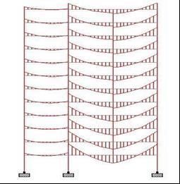
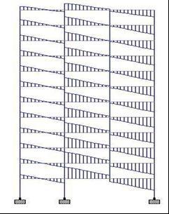
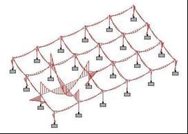
Fig9:ProgressiveAnalysis&DesignresultsfromSTAAD Pro(Case3):
12. Beam design from STAAD Pro:
WidthofBeam = 400mm
DepthofBeam = 700mm
LengthoftheBeam = 6000mm
Concretegrade = M30
Steelgrade = Fe415
Main reinforcement:
Provide5nosofbars#32atthebothfaceofspansection.
Shear reinforcement: Provide 8mm bars @ 2 legged verticalstirrupsat200mm c/c
13. Column design from STAAD Pro:
WidthofColumn = 700mm
DepthofColumn = 700mm
Concretegrade
Concretegrade=M30
Steelgrade =Fe415
Main reinforcement:
Provide16nos.of32mmbars
Lateral reinforcement: Provide8mm#300mmc/caslateralties
International Research Journal of Engineering and Technology (IRJET) e-ISSN: 2395-0056
Volume: 11 Issue: 04 | Apr 2024 www.irjet.net p-ISSN: 2395-0072
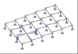
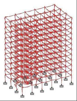
Fig10:ProgressiveAnalysis&DesignresultsfromSTAAD Pro(Case4):
14. Beam design from STAAD Pro:
WidthofBeam = 400mm
DepthofBeam = 700mm
LengthoftheBeam = 12000mm
Concretegrade = M30
Steelgrade = Fe415
Main reinforcement:
Provide9nosofbars#32atthebothfaceofspansection.
Shear reinforcement:
Provide 8mm bars @ 2 legged verticalstirrupsat100mm c/c
15. Column design from STAAD Pro
WidthofColumn = 800mm
DepthofColumn = 800mm
Concretegrade
Concretegrade=M30
Steelgrade =Fe415
Main reinforcement:
Provide20nos.of32mmbars
Lateral reinforcement:
Provide8mm#300mmc/caslateralties
This study illustrates the inherent ability of seismically designed RC beam- column frames to resist progressive collapse. Themainobjective ofProgressivecollapsedesign of buildings is to avoid total catastrophic damage and to restrictthestructuraldamagescaused,tothe performance limit of the building.
reinforcedconcretebuildings.Themainparametersstudied were the axial load, flexure, and shear reinforcement requiredforthemomentresistingconcreteframedbuildings designedfor Dead load, LiveloadandSeismicloads.The columnremovalhasbeendoneaspertheGSAcriteria.
Fromthisstudy,itisobservedthattoavoidtheProgressive failure of beams and columns, after failure of particular column due to extreme loading from blast, adequate reinforcement and in some cases increasing the cross sectionaldimensionswillavoidtheProgressivefailureofthe structure. We found that Case 4 beams and columns are gettingcritical among allothercases,ifweprovideCase4 resultantsectionandadditional reinforcementsforall the columns and beams in base floor we could avoid the structurefromprogressivecollapse.Forconcretebuildings designed for Dead, Live, and Seismic loads, progressive collapsepreventionaspertheGSAcriteriacanbeachieved withsmallincreaseinreinforcement&concretecost.
[1] ANSI/ASCE 7-98, “American Society of Engineers, Minimum Design Loads for Buildings and Other Structures,”AmericanSocietyofCivilEngineers,Reston, VA,1998,pp.168.
[2] Applied Research Associates, Inc. (2005). ‘’Protective DesignandSecurityImplementationGuidelines(Draft), “Prepared for the US General Service Administration, Washington,D.C.
[3] 3DOD.(2005).Designofbuildingstoresistprogressive collapse. Unified Facilities Criteria, UFC 4-023- 03, Department of defense, USA. www.wbdg.org/ccb/DOD/UFC/ufc_4_023_03.pdf
International Research Journal of Engineering and Technology (IRJET) e-ISSN: 2395-0056
Volume: 11 Issue: 04 | Apr 2024 www.irjet.net p-ISSN: 2395-0072
[4] Dusenberry, D., Cagley, J., Aquino, W. (2004), Case studies. Multihazard Mitigation Council national workshoponBestpracticesguidelinesforthemitigation ofprogressivecollapseofbuildings.NationalInstituteof BuildingSciences(NIBS).Washington,D.C.
[5] STAAD PRO Advanced structural analysis program, VersionV8i.
[6] Explanatory examples for ductile detailing of RC buildings,Dr.R.K.Ingle,IITKanpur.
[7] FEMA-403. (2002). World Trade Center building performance study: Data collection, preliminary observationsandrecommendation.Report:FEMA403. Federal Emergency Management Agency (FEMA). Washington,D.C.
[8] FEMA-427. (2003). Primer for design of commercial buildings to mitigate terrorist attacks. Report: FEMA 427.FederalEmergencyManagementAgency(FEMA). Washington,D.C.
[9] IS 1893 (part 1), Indian StandardCodeofPractice, CriteriaforEarthquakeResistantDesignofStructures, BureauofIndianStandards,NewDelhi,2002.
[10] IS 456; Indian Standard Code ofPracticeforPlain and Reinforced concrete, Bureau of Indian Standards, NewDelhi,2000.