
International Research Journal of Engineering and Technology (IRJET) e-ISSN: 2395-0056
Volume: 11 Issue: 04 | Apr 2024 www.irjet.net p-ISSN: 2395-0072
International Research Journal of Engineering and Technology (IRJET) e-ISSN: 2395-0056
Volume: 11 Issue: 04 | Apr 2024 www.irjet.net p-ISSN: 2395-0072
Ayush Pandey1, Vikash Dwivedi2
1M.Tech (ME) Scholar, Department of Mechanical Engineering, B. N. College of Engineering & Technology Lucknow, Uttar Pradesh, India
2 Assistant Professor, Department of Mechanical Engineering, B. N. College of Engineering & Technology Lucknow, Uttar Pradesh, India ***
Abstract - Metal matrix composites (MMCs) represent a crucial category of style and square measure masseconomical structural materials that square measure encouraging each field of manufacturing tenders. It takes Associate in Nursing collective curiosity in mixtures having solidity and short price backups. Amid varied intermittently spread artifacts castoff, aluminum oxide is an amongst the foremost cheap then compactness strengthening out there massive amounts for instance solidexcessthrough-inventionthroughoutburningofcoal inthermalpowerplants.Hereafter,mixturesbyaluminum oxide as strengthening square measure possible beat value fence aimed at varied unfold solicitations in motorized and little engine solicitations to supply Al matrix forged element mixtures, wet ability the ceramic atomsbyliquidAliscrucialtoboostwetability,partssuch as aluminum oxide square measure adscititious into Al soften to include the ceramic particles. the current work has been targeted on the employment of pr out there industrial waste. Aluminum oxide in helpful manner by dispersing it into aluminum oxide matrix to made composites by mechanical stir casting. Wide size varies (0.1- 100μm) aluminum oxide elements were used. The properties like tensile strength, hardness, toughness whicharerelatedtomechanicalisinvestigatedduringmy work . The experimental investigation of hybrid metal matrix composites with Aluminium and Alumina reinforced aluminum alloy (Al 6064) composites samples 5%, 10%,15%, 20%,25% and 30% volume fraction applied for the purpose of production and testing of the materials. Also the machining parameters of Lathe Machine in turning namely the speed, feed, depth of cut and nose radius are optimize by using response surface methodology.
Keyword-MMCs, Al2 O3 , Turning operation in Lathe, RSM, Mechanical Properties of metal etc
1.1. Metal Matrix Composite
Metal matrix composites normally, carries with it a minimum of 2 elements, first is that metal matrix, other element is strengthening. Matrix is outlined as a metallic
completely told belongings, however a pure metal isn't typically castoff because the medium it's typically Al alloy withintheefficiencyofthe compoundthematrixandalso strengthening square measure varied along. Before few years, expansion of metal matrix composite (MMCs) receivedinternational courtesyon accountof theirhigher strengthandtoughnessadditionallygreatattireresistance andcreepresistancecontrasttotheirconformingalloys.
Aluminums metal matrix composites (Al MMCs) square measure being thought of as a bunch of latest advanced materials for its light-weight mass, high strength, high specific modulus, low co-efficient of thermal growth and smart wear resistance properties. Combination of those propertiesisn'tobtainableduringaconservativematerial.
1.2. Advantages of MMC:
Cover patterns and ply buildup during a half are often wont to offer the desired mechanical properties in varied tips.
Excellent strength-to mass and stiffness-to-mass ratiosareoftenachievedbycompoundMaterial
Higherelectricalandthermalconductivities.
Nowetnessabsorption.
Highercrossstiffnessandstrength.
Fireconfrontation
Highertemperaturecapability.
1.3. Disadvantages of MMC:
Compound production strategies for fiberreinforcedsystems(exceptfor casting).
Relativelyundevelopedtechnology.
Highervalueofsomemeasurable systems.
1.4. Production Techniques of Metal Matrix Composite. Spray co-deposition method
It is an economical method of producing a Particulate composite.Inthismethodalloy to besprayedismelted in a flask by induction heating. The flask is pressurized and the metal is ejected through a nozzle into an atomizer
International Research Journal of Engineering and Technology (IRJET) e-ISSN: 2395-0056
Volume: 11 Issue: 04 | Apr 2024 www.irjet.net p-ISSN: 2395-0072
where, at the same time, particles are injected into the atomized metal and dropped on a preheated substrate placedinthelineofflight.Oncollectorasolidcreditisbuilt up. The shape of the final formation depends on the atomizing condition and the shape and the motion of the amasser.
Thecrucialthingistocreategoodmoisteningbetweenthe particulate strengthening and the molten metal, in this process. Micro structural in equalities can cause particularly particle collection and sedimentation in the melt and then during solidification. In similarity in strengthening spreading in these cast composites could also be a problem as a result of contact between suspended ceramic particles and moving solid-liquid interface during Solidification. The manufacture costs of MMCs are very low by use of this process it is the main advantageofthisprocess
Cutting speed (V): Cuttingspeedisrelativevelocities amongcuttingtoolandworkpiece.InturningonLathe machineitisthespeedoftheworkpiecewhileindrilling ondrillingmachine,itisthespeedofthecuttingtool.In turning,itisgivenbythesurfacespeedoftheworkpiece, V=πDN/1000
WhereDisthediameteroftheworkpiece.
Depth of cut (d): It is the distance the cutting tool cuts into the work piece. In turning on lathe machine, for example,itisgivenby:
d=(D1-D2)/2.
Feed (f): It is movement of the tool per revolution. In turning, itisthedistancethetool travelsinonerevolution of the work piece and is given the units of mm/rev or in/rev.
Tool rake angle: The rake angle specifies the ease with which a metal is cut. Higher the rake angle, better is the cutting and less are the cutting forces .There is the
maximumlimittotherakeangleandthisisnormallyofthe order of 150 for high speed steel tools .It is possible to have rake angle as zero or negative. These are generally used in case of highly brittle tool materials such as carbidesorlozengesforgivingextrastrengthtotooltip.It isoftwotypes (a)Backrakeangle(b)Siderakeangle
Back rake angle: It is the angle between the face of the tool and a line parallel to the base of the tool and measured in a plane erect through the side cutting authority. This angle is positive if the side cutting edge slopedownstairsfromthepointtowardstheShankandis negativeiftheslopeofthesidecuttingedgeisreverse.
Side rake angle: Itistheanglebetweenthetoolfaceanda lineparalleltothebaseofthe toolandmeasuredinaplane perpendicular to the base and the side cutting edge. The side rake angle is negative if the slope is towards the cuttingedgeandconstructiveiftheslopeisawayfromthe cuttingedge.
Tool nose radius: Nose radius isprovided to removethe fragile junction of the tool. It increases the tool life and improvessurfacefinish.Smallnoseradiusisusedforsmall cuttingdepth,reduceshakingandlargenoseradiusisused forsubstantialfeedrate,largedepthofcut.
Y.Iwaietalin2000studiedthedryslidingwearbehavior of die-cast ADC12 aluminum alloy composites bulletproof withshortalumina fiberswerestudied by using a pin-ondisk wear tester. From the analysis of wear data and detailedexaminationof(a)wornsurfaces,(b)theircrosssections and (c) wear debris, two modes of wear mechanisms have been identified to be functioning, in these materials and these are: (i) glue wear in the case of unreinforcedmilieumaterialandinMMCswithlowVfand (ii)scratchywearinthecaseofMMCwithhighVr.[1]
C.G.Kangetal in2000deliberatetheMetal matrixfusions (MMCs) fabricated by the compocasting process show a homogeneous scattering of the reinforcing fiber in the matrix.Microstructuresurveillanceof hotextrudedMMCs reveals that as the extrusion ratio intensifications, the fiber alignment becomes improved, but fiber fracture occurs more severely. The mechanical properties of hot extruded MMCs are better than those of the milieumetal, withtheomissionof the elongationatfailure,andare not influencedsuggestivelybytheextrusiontemperature.The tensilestrengthandresistanceofMMCsareimprovedtoa greater degree by hot extrusion using a constant-strainrate die. Also, there exists a critical extrusion ratio that givesmaximumstrength,[2]
B. Venkataraman et al in2000 investigated the slithering friction and wear behavior of aluminium (Al), aluminium
International Research Journal of Engineering and Technology (IRJET) e-ISSN: 2395-0056
Volume: 11 Issue: 04 | Apr 2024 www.irjet.net p-ISSN: 2395-0072
alloy 7075 (Al-7075) and SiC particulate reinforced aluminium matrix composites (Al-SiC) under gasping sliding wear positions. The wear tests were approved out ataslidingspeedof1m/sandatnormalloadrangingupto 220N.Theoverallobjectiveofthestudy isto improveour current indulgent with regard to the influence of mechanically mixed layers (MML), which form on the surfaceofthewearisomematerialduringthecourseofthe wear test, on the friction and wear comportment. The aluminium alloy 7075 was used in both solution treated and aged conditions. The aluminium based metal matrix complexesstudiedlimited10and40vol%ofSiCparticles astheunderliningphase [3].
O. Yılmaza et al in 2001 studied the effects of volume fraction,Al2O3particlesizeandpossessionsofporosityin thecompositesontheabrasivewearresistanceof compocastingAlalloyMMCsdifferentabrasiveconditions..
Followingobjectivesaredecided.
Manufacture of Al6082/Al2O3 metal matrix mixtures with different % of bolstering by Stir casting method.
Microstructure surveillance of all invented samplestoobservedispersalof reinforcement.
Investigation of mechanical belongings of all samples.
Properties of turning parameters on dimensional deviationofmetalmatrixcomposite
By aluminum alloy Most of the automobile parts, aerospace structures and its allied substructure are made by considering Al 6082 which was used for making pressure vessel cylinders is now testing for aircraft structures in this context. Al 6082 has more corrosion resistanceand itcanbeseen informsofextruded rod bar and wire and extruded shapes. It can be easily machineable and can have an extensive variation of surface finishes. It also has good electrical and thermal conductivities and ishighly reflective to heat and light. Al 6082 offers extremely low maintenance due to the superior corrosion resistance. Al 6082 is only one-third themassofcastiron,withabout75%ofequivalenttensile strength. The tensile strength on circular rod specimen of Al 6082 is verdict out by applying the loads on universal testing machine with various dimensions in this analysis. The analytical results were found acceptable to offer the anotheralloyforaircraftstructures.
Thephysicalandmechanicalpropertiesofaluminumalloy (6082) have been reviewed from literature data for the resolutionofillustratingthemechanicalformanufacturing methodin engineeringsubmission.
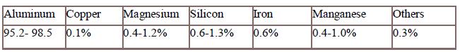
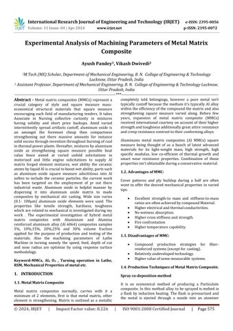
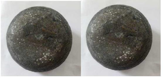
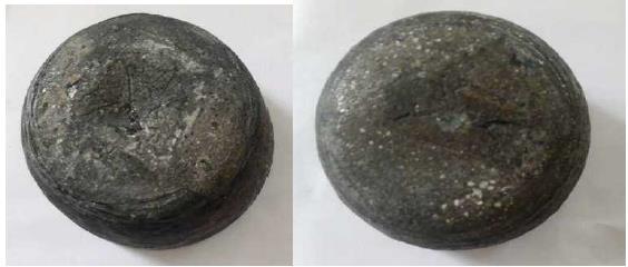
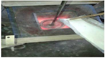
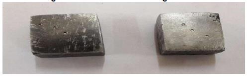
The work materials used in the present work are aluminium alloy 6082 and aluminium oxide (Al2O3 as reinforcement). These materials are chosen due to their easily mixable property and gives good mechanical properties. First of all the aluminium alloy (Al6082) is heated up to its melting temperature ina electric furnace and then aluminium oxide isheated and mixed gradually in molten aluminium alloy with the help of stirrer. The mixerisleftfor cool down in the crucible inwhich itwas meltedandmixed.Therearesixsamplesindifferentratios whichare preparedfortestingmechanical propertiesand choosingthebest.TheratiosareshownbelowintheTable.
Table 5.1 Composition selection
International Research Journal of Engineering and Technology (IRJET) e-ISSN: 2395-0056
Volume: 11 Issue: 04 | Apr 2024 www.irjet.net p-ISSN: 2395-0072
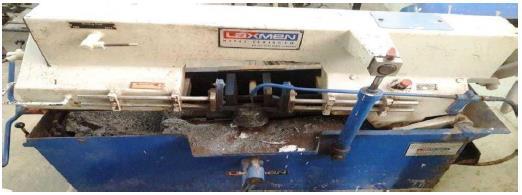
Optimization is a process of arranging different input variablesto getthe best output.In this project optimizing thefourparameterslikefeedrate,Depthofcut,speedand tool nose radius, and study the behavior of these parametersondimensionaldeviation.
Response surface methodology (RSM) is a collection of mathematical and statistical techniques for empirical model construction. By careful design of experiments the objectiveistooptimizearesponse(outputvariable)which is influenced by several independent variables (input variables). An experimentation is a series of tests, called runs, in which changes are made in the input variables in order to identify the reasons for changes in the output response. Originally, RSM was developed to model experimentsresponses(BoxandDraperin1987)andthen migrated into the modeling of experiments. In physical experiments, inaccuracy can be due ,for example, to measurement errors while, in computer experiments, numerical noise is a result of incomplete convergence of iterative processes, round -off errors or the distinct representationofcontinuousphysicalphenomena.InRSM the errors are assumed to be random. The mostextensive applications ofRSM are in the particular situations where several input variables potentially influence some performancemeasuresorqualitycharacteristicsarecalled the response. The input variables are sometime called
independent variables, and they are subjected to the controloftheengineerorscientists.
6.1. ANALYSIS OF MICROSTRUCTURE
Microstructures of the MMC models are seen using metallurgical microscope. When describing the structure of a material, we make a clear difference between its crystal structure and its microstructure. The tenure ‘crystal structure’ isused to label theaverage positions of atoms within the unit cell, and is completely itemized by the lattice type and the fractional arranges of the atoms. The term ‘microstructure’ in metal matrix composites is used to define the appearance of the strengthening material. A realistic working definition of microstructure is “The arrangement of phases and defects within a material.

Figure 6.1 Microstructure of different samples (a) 2.5% Reinforcement, (b) 5% Reinforcement, (c) 7.5% Reinforcement, (d) 10% Reinforcement
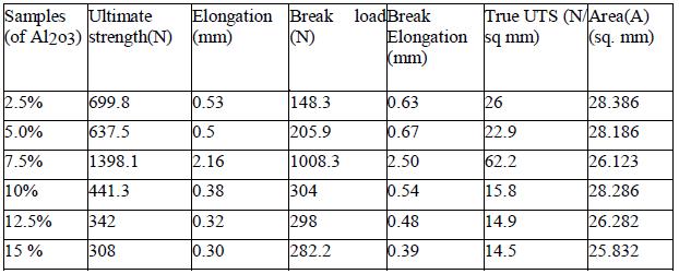
6.2. ANALYSIS OF TENSILE STRENGTH
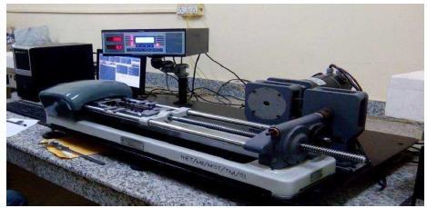
Tensile testing of MMC is conceded out on Tensometer machine. Tensometer is a device used to calculate the tensile properties of materials such as their Young’s Modulus and tensile strength. It’s a common testing machineloadedwithasamplebetweentwogripsthatare eitheradjustedmanuallyorautomaticallytoapplyforceto themodel.Themachineworkseitherbydrivingascrewor byhydraulicram.Testingisdonebyholdingthespecimen in the jaws of the Tensometer. The load is applied slowly and the material starts elongating. After the maximum loadreachedthespecimenbreaks
International Research Journal of Engineering and Technology (IRJET) e-ISSN: 2395-0056
Volume: 11 Issue: 04 | Apr 2024 www.irjet.net p-ISSN: 2395-0072
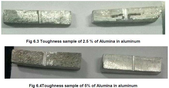
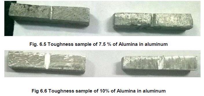
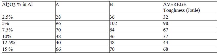
6.3.
In the MMC, specimen’s toughness is verified by breaking itwith impacting force of a hammer assessing 21 kg. The Hammerisleavedfrom140degreeofanglewiththeinitial energy of 300 J. We can see the table for results while testingasfollows.
6.4.
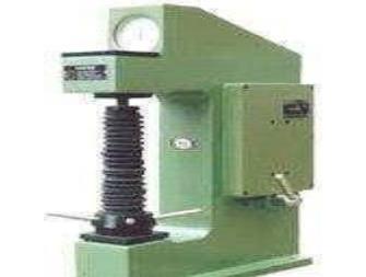
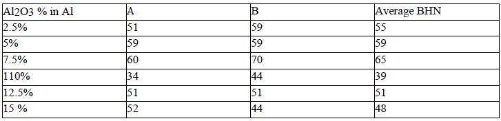
Hardness Test is conceded out on the Brinell hardness testingmachine.Inthistestastandardsteelballispressed into the surface of the specimen by a slowly applied load,
which is maintain on the specimen for definite time the diameter of the impress so obtained is measured by a microscope and the Brinell Hardness Number (BHN) is foundoutbythefollowingformula:
BHN = Load / Area of impression/indentation = 2P / π D (D-√D2 -d2)
Where, P = Load (kg), D = Diameter of ball in mm. (2.5 mm) d = Diameter of indentation circle found from microscope
7. CONCLUSIONS
Thefollowingconclusionscanbedrawnfromanalysis:
Within the investigated range of process parameters,lowerspeed(100m/min),lowerfeed (0.15mm/rev.)andlowerdepthofcut(0.20 mm)
International Research Journal of Engineering and Technology (IRJET) e-ISSN: 2395-0056
Volume: 11 Issue: 04 | Apr 2024 www.irjet.net p-ISSN: 2395-0072
and rake angle (-9 .00) are preferred for low dimensional deviation of machined A6064/7.5% Al2O3metalmatrixcomposite.
Within the process parameters range; dimensional deviation of machined A6064/7.5%Al2O3 metal matrix composite decreases, by increasing the speed, feed rate and depth of cut and increases by increasing rake angle.
Mechanical properties are better by adding the reinforcement material Alumina at 7.5% in Al6064
Thevalueofdimensionaldeviationis2.5933
8. FUTURE SCOPE
The present work has been completed but permits way forfurtherworkinfuture:
The work can be carried out by making use of other design technologies like fractional factorial design, design expert tools, Box bancken design etc.
Composite can be prepared by other matrix material and other reinforcing materialslike SiC, B4Cetc.
The work can be carried out by taking more machining parameter like feed, Speed, Depth of cut,Rakeangle,Noseradius,Coolantuse etc.
REFERENCES
[1] Y. Iwai , T. Honda , T. Miyajima ,Y. Iwasaki and M.K. Surap “Dry sliding wear behavior of Al2O3 fiber reinforced aluminum composites” CompositesScienceandTechnology60(2000).
[2] C.G. Kang, N.H. Kim and B.M. Kim “The effect of die shape on the hot extrudability and Mechanical properties of 6061 Al/Al2O3 composites” Journal of Materials Processing Technology100(2000).
[3] B. Venkataraman , G. Sundararajan “Correlation between the characteristics of the mechanically mixed layer and wear behaviour of aluminium, Al-7075 alloy and Al-MMCs” Wear 245 (2000) 22–38.
[4] O. Yılmaza and S. Buytoz “Abrasive wear of Al2O3-reinforced aluminium-based MMCs” Composites Science and Technology61 (2001) 2381–2392.
[5] Y. Sahina,, M. Kok and H. Celik “Tool wear and surface roughness of Al2O3 particle- reinforced aluminiumalloycomposites”JournalofMaterials ProcessingTechnology128(2002)280–291.
[6] TongxiangFan, DiZhang, GuangYang, Toshiya Shibayanagi and Massaki Naka “Microstructure and interface characteristics of B4C, SiC and Al2O3 reinforced Al matrix composites: a comparative study” Journal of Materials ProcessingTechnology142(2003)738–743.
[7] M.Kok“Productionandmechanicalpropertiesof Al2O3 particle-reinforced2024 aluminium alloy composites” Journal of Materials Processing Technology161(2005)381–387.
[8] Pirondi and L. Collini “Analysis of crack propagation resistance of Al– Al2O3 particulatereinforced composite friction stir welded butt joints”InternationalJournalofFatigue31(2009) 111–121
[9] Mehdi Rahimian,, Naser Ehsani, Nader Parvin, Hamid reza Baharvandi “The effect of particle size,sinteringtemperatureandsinteringtimeon thepropertiesofAl–
[10] Al2O3 composites, made by powder metallurgy” Journal of Materials Processing Technology 209 (2009)5387–5393.
[11] ChinmayR.DandekarandYungC.Shin“Effectof porosity on the interface behavior of an Al2O3 –aluminum compositea molecular dynamics study” Composites Science and Technology 71 (2011)350–356.
[12] 11.S.K. Singhal , Renu Pasricha , Satish Teotia , Girish Kumar and R.B. Mathur “Production and characterization of Al-matrix composites reinforced with amino- functionalized carbon nanotube Composites” Science and Technology 72(2011)103–111.