
International Research Journal of Engineering and Technology (IRJET) e-ISSN: 2395-0056
Volume: 11 Issue: 04 | Apr 2024 www.irjet.net p-ISSN: 2395-0072
International Research Journal of Engineering and Technology (IRJET) e-ISSN: 2395-0056
Volume: 11 Issue: 04 | Apr 2024 www.irjet.net p-ISSN: 2395-0072
Ms. Sneha Baliram Tambe1 , Mr. Samadhan A. Patil2 , Ms.Naina Raut3
Ms. Sneha Baliram Tambe, Dept. of Electrical Engineering, YTIET ,Karjat, Maharashtra, India
Mr. Samadhan A. Patil, Dept. of Electrical Engineering, YTIET , Karjat, Maharashtra, India.
Ms.Naina Raut, Dept. of Electrical Engineering, YTIET Karjat, Maharashtra, India.
Abstract - The use of induction generators to generate electricity from unconventional sources has attracted considerable interest from energy researchers. Based on economy, high technical knowledge and environmental friendliness to provide electricity used for all development. Wind energy plays an important role in developing an environmentfriendlyeconomywithlowcarbonfootprint.This paper provides an overview of wind turbine generator technologyandcomparestheadvantagesand disadvantages when applied to wind energy applications. Traditionally, DC motors, synchronous motors, and squirrel-cage induction motors have been used to generate small electrical currents. For medium and large wind turbines, doubly-fed induction generators are currently the dominant technologies, while permanent magnetic, switched reluctance and high-temp superconductinggeneratorshavebeenextensivelyresearched and developed over many years. This paper discusses the topology and characteristics of these devices, including their practical considerations regarding design, control and operation.
The paper presents a summary of wind turbine technology through a literature review of wind turbine systems followed by a discussion of systems applied on doubly fed induction generator wind turbines in particular.
Key Words: Doubly-fed induction generators, SynchronousGenerator,AsynchronousGenerator,Radial fluxpermanentmagnet,AircoreGenerator.
1.1 .Utilization of wind energy
Wind energy was used as early as 5000 B.C. when they sailedacrosstheNile.Itisrecordedthatin200B.C.Since then, wind has been used as an energy source in ancient China and the Middle East to pump water, grind rice, and propelcarsandships.Thefirstrecordedwindmillwasbuilt inthefirstcenturyB.C.orthefirstcenturyAD.Effectively, this wind turbine is used to convert kinetic energy into mechanicalenergy.
Thesewindturbinesthemselvestendtobesmall(lessthan 100kW)butcanbedesignedforlargerwindturbines(5MW orspecified).Untiltheearly1990s,windprojectsliterally got off the ground, driven primarily by government and
industrialpolicies.The1990salsosawashiftinfocusfrom onshore to offshore development in key wind developing countries,particularlyinEurope,Offshorewindfarmswere first proposed in Germany in the 1930s, first installed in Sweden in 1991 and in Denmark in 1992. By July 2010, offshorewindturbineswereinstalled2.4GWestablishedin EuropeCompared toonshore wind,offshore windenergy hassomeinterestingpropertiessuchaswindspeed.
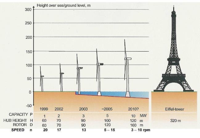
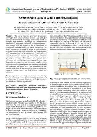
Overthepastthreedecades,windturbineshaveexperienced tremendousgrowthastheglobalwindmarketcontinuesto growandaccelerate.Attheendof2009,globalcapacitywas 160 GW. The contribution of wind energy to the global electricitymarketisestimatedtoincreasefrom1%in2008 to8%by2035.Thiscanonlybeachievedbybuildinglarger windturbinesandputtingmoreintothewindindustry.In termsofscale,largemegawattwindturbinesarestartingto appearintheEU,theUS,andnowChinaandIndia.Typically thelargestwindturbinesinstalledinutilitygridsare1.5-5 MWwhile7.5to10MWareinhighdevelopment,asshown inFig-1,ModernwindturbinesarenowReliable,quiet,costeffectiveandcommerciallycompetitive,whilewindturbine technology has been demonstrated are also proficient. Currenttechnicalchallengesaregenerallyrelatedtoeverincreasing wind turbine size, power transmission, energy storage, energy efficiency, complex design and fault tolerance .Nowadays, it is widely recognized that wind poweristhemainsourceofeconomicallyviablerenewable energy available. A global map of wind power potential is shown in Figure 2. However, wind power is variable in natureandsuchapplicationsrequirehighreliabilityandare
International Research Journal of Engineering and Technology (IRJET) e-ISSN: 2395-0056
Volume: 11 Issue: 04 | Apr 2024 www.irjet.net p-ISSN: 2395-0072
mostlyavailablewhenthemarketisstilllookingtoreduce weight,challengesandoperatingcosts.
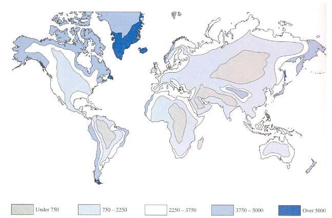
Fig -2:Theworld’senergypotentialforland-basedwind turbines.
Themainobjectiveofthissessionistostudyanddesignthe proposedgenerator.Theproposedgeneratorisaradialflux permanentmagnetgeneratorwithtworotortopology.The stator is metal-less or ‘in air’, hence the name. This generatorisasingle-sidedgenerator,originallydesignedto usewindpower.
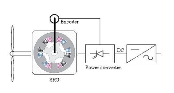
Clearly,windenergyfiguresprominentlyingovernmentand institutionalagendas.However,therearesomestumbling blocks in this widespread approach. Wind turbines come withdifferenttopologies,architecturesanddesignfeatures. Thewindturbinegenerationsystemschematicisshownin Figure3.Someoptionsforwindturbinetopologiesareas follows.
•Orientationoftherotoraxis:horizontalorvertical;
•Rotorposition:upwindordownwindofthetower;
•Constantorvariablerotorspeed;
•Hub:solid,flexible,gimbalorhingedcable;
•Stiffness:mobileorbrittle;
•Numberofblades:one,two,threeormore;
•Powercontrol:stall,pitch,yaworaerodynamicsurface;
•Yawcontrol:enabledordisabled.
This paper focuses only on horizontal axis wind turbines (HAWTs), which is a standard wind turbine topology, as highlightedinFigure4
Windturbinesconsistofturbinebladesandrotors,critical mechanical parts, drive train and generators. More than 30%ofthetotalcapitalexpendituregoestoemissionsfrom offshore wind projects. Wind turbines are often built in relatively inaccessible areas imposing certain design restrictions.Incoastalareas,thisistheonlyplaceyoucango forcleaningonceayear.Consequently,thefaulttoleranceof wind turbines is important for the development of wind turbines.
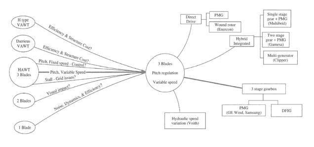
-4:Commonlyagreedwindturbinetypeandits divergence.
Themaincomponentofawindturbineisitsdrivetrainthat connects the aerodynamic rotor to the electrical output. Optimizationofwindturbinegeneratorscannotbeachieved without considering the mechanical, structural, hydraulic andmagneticperformanceofthedrivetrain Generally,they can be divided into four categories according to their structure:
• Conventional: high-speed gearbox and generator with fewertwinpoles.
•Directdrive:Drivetrainwithoutalow-speedgearboxand generator.
• Hybrid: Drive train with gearbox and generator speed betweentheabovetwotypes.
• Multiple generators: Drive train with more than one generator.
Drive train topologies can raise issues such as rotor and gearbox/ bearing integration, separation of gear and generatorshaftsfrombendingloadmachines,integrity,and loadpathsalthoughitcanbeeasytoservicewindturbine components if separated like gearbox, bearings and generatorislargelyinfavoroftheplanningofDrivetrain components.
1.2 Wind Turbine Generators
One of the limiting factors for wind turbines is the engineering of their generators. Academics and industry disagree on the optimal wind turbine technology. Traditionally, there are three main types of wind turbine generators(WTGs)thatcanbeconsideredforwindturbine systems,thesearedirectcurrent(DC),alternatingcurrent (AC) synchronous, AC asynchronous. Generators are also available and can in principle be either fixed or variable speed. Due to variable wind forces, variable speeds are operatedintheWTGwhichreducethephysicalstrainonthe
International Research Journal of Engineering and Technology (IRJET) e-ISSN: 2395-0056
Volume: 11 Issue: 04 | Apr 2024 www.irjet.net p-ISSN: 2395-0072
turbinebladesanddrivetrain,improvingtheaerodynamic efficiency,torqueandtransientbehaviorofthesystem.
Generally in conventional DC motors, the field is on the statorandthearmatureisontherotor.Thestatorconsists ofseveralpolesthatareenergizedbypermanentmagnetsor DCfieldcoils.Ifthedeviceiselectricallypowered,itusually followstheconceptofashunt-woundDCgenerator.
Ingeneral,thesetypesofDCWTGsarerareinwindturbine applicationsunlessthepowerdemandislowwheretheload is physically close to the wind turbine, for thermal applicationsorbattery.
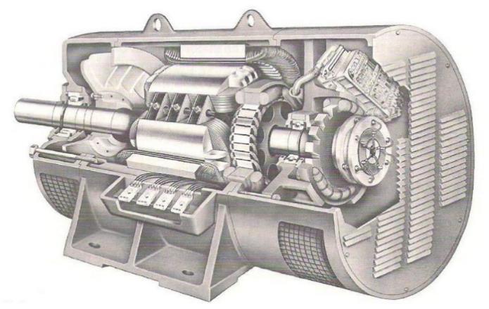
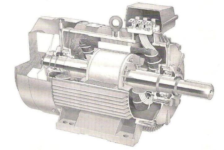
Sincetheearlydevelopmentofwindturbines,considerable effort has been devoted to the use 3 phase synchronous machine. AC synchronous WTGs can take constant or DC excitationfromconstantmagnetsorelectromagnetsandare calledPMsynchronousgenerators(PMSGs)andelectrically excitedsynchronousgenerators(EESGs)respectively.For fixed-speedsynchronousgeneratorsconnectedtothegrid throughthemedium,therotorspeedmustbemaintainedat synchronousspeedotherwisesynchronizationwillbelost. Synchronousgeneratorsareaprovenmachinetechnology because their efficiency in electricity generation has been studied and widely accepted for a long time. A cutaway diagramofaconventionalsynchronousgeneratorisshown inFigs.7.Inprinciple,thereactivepowercharacteristicsof synchronousWTGscanbeeasilycontrolledbyfieldcircuits forelectrical excitationdespitebeingtransmittedthrough the power grid, synchronous WTGs have a low damping effectsothatthepowerofdrivetraintransientswillnotbe absorbed.Asa result,anadditional dampingelement(e.g. flexiblecouplingofthedrivetrain)isrequired,oragearbox assemblymountedonspringsanddampers,whichrequires asmoothoperationtosynchronizetheirfrequencywiththe gridfrequencywheninstalledinthegrid.Inaddition,they aregenerallymore
In recent decades, PM generators are increasingly being usedinwindturbineapplicationsduetotheirhighefficiency and low size. These devices are generally referred to as permanent magnet synchronous generators (PMSGs) and are considered the device of choice in small wind turbine
generators.Thedesignofthegeneratorisquitesimple.Asin Figure 8. A solid PM is placed on the rotor to create a constant magnetic field and an electrical energy is taken fromarmature(stator)byusingacommutator,slipringor brush. Sometimes the PM is made of cylindrical cast aluminum -They can reduced cost by adding cost to the rotor. The principle of operation of the PM generator is similar to the synchronous generator except that the PM generator can operate asynchronously. The advantage of PMSG is that commutators, slip rings and brushes are removedmakingmachinesmorerobust,reliableandsimple. TheuseofPMeliminatesfieldwinding(anditsassociated powerloss)butfieldcontrolisnotpossibleandthecostof PMcanbeprohibitivelyhighforlargemachines
Because the actual wind speed fluctuates, PMSGs cannot generatefixed-frequencyelectricity.Asaresult,thepower grid must be connected with an AC- DC-AC conversion driven by a power converter. That is, the generated AC voltage(ofvariablefrequency)isfirstrectifiedtofixedDC, andthenconvertedbacktoACvoltage(offixedfrequency) Use of this permanent magnet device for direct drive applicationisalsoveryattractive.Obviouslyinthiscasethe peskygearboxesthatcausemostwindturbinestofailcanbe eliminated.
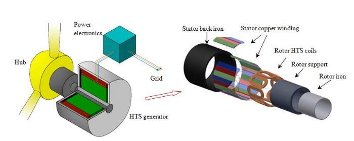
One possible type of synchronous generator is a high temperaturesuperconductinggenerator.SeeFigure9fora multi-MW,lowspeedHTSsynchronousgeneratorsystem. The device includes stator back metal, stator copper winding, HTS field coil, rotor core, rotor support system, rotor cooling system, cryostat and external refrigerator, electromagnetic shield and damper, bearing, shaft and housingStatorkeepsHTScoilswarmtheloweroperating conditions in machine design , rotor, cooling and gearbox designcanposeparticularchallenges.
International Research Journal of Engineering and Technology (IRJET) e-ISSN: 2395-0056
Volume: 11 Issue: 04 | Apr 2024 www.irjet.net p-ISSN: 2395-0072
Superconductingcoilscancarry10timesmorecurrentthan conventionalcopperwireswithlittletoleranceandlossesof conductor.Superconductorswillcertainlyeliminateallfield circuit power losses and superconductivity's ability to increase current density allows higher magnetic fields, greatly reducing the number and size of wind turbine generators.Thecompany“Siemens”offerstheworldinthe first superconducting wind turbine generator of 4 MW synchronousgeneratorwasinstalledsuccessfully.However, many technical challenges are encountered, especially for long-lived, low-maintenance wind turbine system. For example,cryogenicsystemsrequireconstantmaintenance sothatcoolingandrecoverytimeaftershutdownisanother issue.
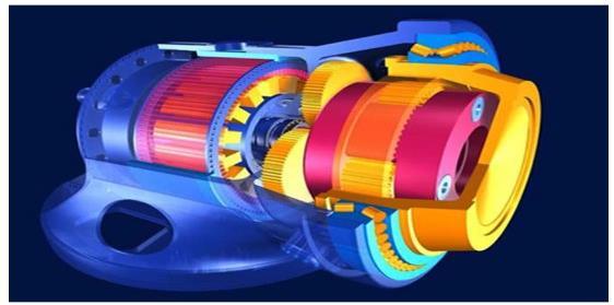
While traditional electricity generation uses synchronous machine, modern wind power systems increasingly use inductionmachines.Theseinductiongeneratorsareoftwo types: fixed speed induction generators (FSIGs) with squirrelcagerotors(sometimesreferredtoassquirrelcage induction generators-SQIG and double-fed induction generators(DFIGs)withwound.Thecross-sectionalimages ofthesquirrel-cageinductiongeneratorandthedouble-fed induction generator are shown in Fig. 10 and Fig. 11, respectively,andtheirconfigurationtopologiesarefurther showninFig.12
Whenathree-phaseACvoltageissuppliedtothestator,a rotatingmagneticfieldisproducedintheairgap.Whenthe rotor rotates at a speed different from the synchronous speed, slip occurs and the rotor circuit is energized. Inductiondevicesaregenerallysimple,reliable,inexpensive, andwell-designed.Theyhavehighdampingandcanabsorb variable rotor speeds and drive train transients (i.e. fault tolerance). But induction machines draw reactive power from the grid so some reactive power compensation is neededsuchastheuseofacapacitororpowerconverters. In a fixed-speed induction generator where the stator is connectedtothegridthroughatransformerandtherotor goes to a wind turbine via gearbox. The rotor speed is assumedtobefixed(ofcoursevaryingoverasmallrange). Until 1998, most wind turbine manufacturers developed constant-speed induction generators of 1.5 MW and less. Thesegeneratorstypicallyoperateat1500revolutionsper minute(rpm).
50Hzutilitygrid,withthree-stagegearbox.
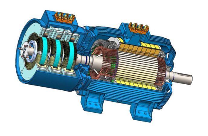
-11:Cutawayofadoubly-fedinductiongeneratorwith arotarytransformer.
SCIGs can be used in variable wind speeds, such as synchronousmachines.However,theoutputvoltagecannot be controlled and the reactive power must be supplied externally.Obviously,fixed-speedinductiongeneratorsare limitedtooperateonlyinaverynarrowrangeofdifferential speeds. Other mechanical drawbacks are related to mechanical size, noise, low performance and reliability. These machines have proven to cause significant performancefailureandsubsequentmaintenance.
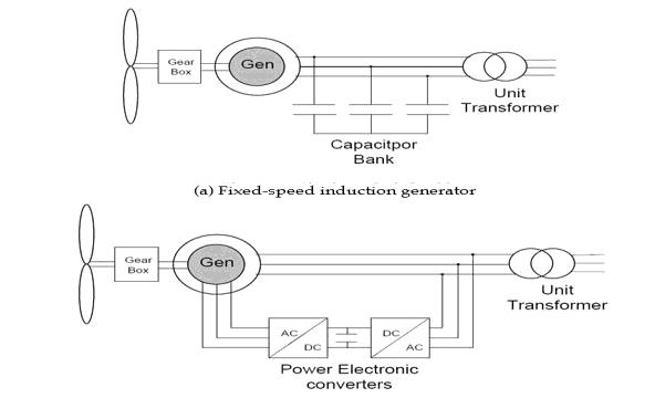
Fig -12:Schematicoftwoinductiongeneratorsystems.
SCIGs have led the wind turbine market over the past millennium, which surpassed the widely adopted DFIG. Morethan85%ofthecurrentlyinstalledwindturbinesuse DFIGandwithDFIGthemaximumcapacityofcommercial wind turbineshasincreased to5 MWinoperation.Inthe DFIGtopology,thestatorthroughatransformerandrotor
International Research Journal of Engineering and Technology (IRJET) e-ISSN: 2395-0056
Volume: 11 Issue: 04 | Apr 2024 www.irjet.net p-ISSN: 2395-0072
andconnecteddirectlytothegridconnectedtothegridvia PWMpowerconverters–Itcancontrolrotorcircuitcurrent, frequency, and phase-angle changes. Such induction generators can operate over a wide slip range (typically ±30%of synchronous speed).Asa resultthey offermany advantagessuchashighpoweroutput,reducedmechanical stressesandvariable,controllablepoweroutput
Reactivepowerforthemagneticcircuitsmustbesuppliedto theentireinductiongeneratorfromagridorlocalcapacitor. Induction generators are susceptible to unstable voltage. When capacitors are used to compensate for the power factor, there is a risk of self-excitation. Additionally, the dampingeffectcancausepowerlossesintherotor.Thereis no direct control of terminal voltage (and thus reactive power),noristhereacontinuousfaultcurrent.
AsshowninFig.12,therotoroftheDFIG ismechanically connectedtothewindturbinethroughadrivetrainsystem, which can have high and low speed shafts, bearings, and gearboxes. The rotor is fed by the bi-directional voltagesourceconverters.Thespeedandtorqueconsumptionofthe DFIG can therefore be controlled by controlling the rotor side converter (RSC). Another feature is that DFIGs can handlesub‐synchronousandsuper‐synchronousstates.The statorconstantlytransmitspowertothegridwhiletherotor can handle power in both directions. The reason for the latteroccursbecausePWMconverterscandelivervoltage andcurrentatdifferentphaseangles.In subsynchronous operation,therotor-sideconverteractsasaninverterand thegrid-sideconverter(GSC)actsasarectifier.Inthiscase, theactivepowerflowsfromthegridtotherotor.Insupersynchronousmode,theRSCactsasarectifierandtheGSC actsasaninverter.Consequently,thereactivepowerenergy flowsfromthestatoraswellasfromtherotortothepower grid.
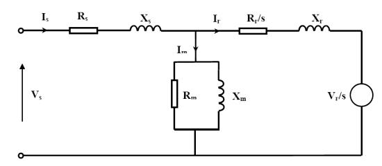
ToanalyzetheperformanceofaDFIG,itisalwaysnecessary to take its counter phase equivalent circuit, as in Fig. 13. Fromthisfigure,wecanseethattheDFIGdiffersfromthe conventionalinductionmachineinwhicharotorcircuitis used voltage is included in order to apply voltage to the rotorcircuit.Theactuald-qcontroloftheDFIGissimilarto theamountofvoltageappliedtothecircuitandthephase control.
Thereluctancerotorismadeoflaminatedsteelandhasno electricalwindingsorpermanentmagnets.Asaresult,the reluctance machine device is simple, easy to manufacture andassemble.Oneobviousaspectistheirgreaterreliability astheycanoperateinaharsherenvironmentorathigher temperatures.Sincereluctancetorqueisonlyafractionof electrical torque, switched reluctance rotors tend to be larger than others with electrical excitations for a given rated torque. If reluctance machines are combined with directdrivefeaturesthedevicewouldbelargertoomuch andheavy,makingitunsuitableforwindenergy.
Windturbinegeneratorscanbeselectedfromcommercial electricmotorswithorwithoutminormodifications.When itisnecessarytotailortheWindturbinegeneratingsystem to a specific location, there are some basic points to consider.
Theseinclude:
Choiceofmachines
Typeofdrivetrain
Brushtopology
Ratedandoperatingspeeds
Ratedandoperatingtorques
Tipspeedratio
Powerandcurrent
Voltageregulation(synchronousgenerators)
Methodsofstarting
Startingcurrent(inductiongenerators)
Synchronizing(synchronousgenerators)
Coolingarrangement
Power factor and reactive power compensation (inductiongenerators)
Powerconvertertopology
Weightandsize
Protection(offshoreenvironment)
Capitalcostandmaintenance.
2.1 Reasons for air core generator being used
Efficiencyishighduetoabsenceoflosses(iron&field culosses)
International Research Journal of Engineering and Technology (IRJET) e-ISSN: 2395-0056
Volume: 11 Issue: 04 | Apr 2024 www.irjet.net p-ISSN: 2395-0072
Doesnotrequiregearboxforspeedupi.e.omittingthe gearbox.
Eliminate the need for gearbox repairs, gearbox maintenanceandcomplexinstallationprocedures.
Noiseisless
Duetoabsenceofironcorecostisless
Powertoweightratioishigh
Duetolightweightinstallationiseasy.
Ithasverylesscoggingeffect.
3. Problem Definition & Objective:
3.1 Definition:
i. The normal wind turbine is suitable for min 10m/s windvelocity&theyareusingeitherStarorDeltatypeof windingfortheirgeneratorsogeneratorgetonlyoneoutput (pairofwire+,-)
ii. If wind velocity less than 10m/s this turbine cannot rotate generator because for starting generator torque is insufficientsoinmax.partofIndiawecannotinstallwind turbine.
3.2 Objective
1) Objectiveofourprojectistomakeasmartgenerator, i.e. according to wind speed it should change the requiredtorquetorotatethegenerator
2) Toincreasethezonesforinstallingthewindturbineby reducingtherequiredairvelocityforwindmill
3) Todesignaspecialtypeofcircuitwhichwillsensethe airvelocityandaccordinglyoperatetherelay
4) To make such a wind mill which will activate and deactivatethewindingaccordingtowindvelocity.
5) Tomaketheprojectinpossiblelowcost.
4. Description and Concept
4.1 Generation of EMF by faraday’s law:
Electrical generators are devices that convert mechanicalenergyintoelectricityandarewellknown.The underlyingworkingprincipleofthesegeneratorsisfoundin Faraday'slawwhichstatesinitsbasicformthatanelectrical difference occurs between the edges of an electrical conductorrunningperpendicularlythroughamagneticfield. In this experiment Faraday uses a magnet and a coil and connecting galvanometer around the coil. Initially the magnet is at rest, so there is no deflection in the galvanometerie.theneedleofthegalvanometeriscentered or at zero. When the magnet moved towards the coil, the needleofthegalvanometerturnsinonedirection.Whenthe magnet is stationary, the galvanometer needle returns to zeroatthatpoint.Nowwhenthemagnetmovesawayfrom thecoil,thereisaslightdeflectionintheneedlebutinthe oppositedirectionandagainwhenthemagnetisstationary atthatpointaboutthecoil,thegalvanometerneedlereturns
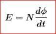
tozeroandasthecoilmovesawayandtowardsthemagnet holding the magnet still It can be seen that, the faster the magnetic field changes, the greater the emf or voltage induced in the coil will be. More specifically, that the electromagneticfield(EMF)inducedinanyclosedcircuitis equal tothetimechangeof themagneticfluxthroughthe circuit
ButaccordingtoFaraday'slawofelectromagneticinduction, therateofchangeoffluxlinkageisequaltoinducedemf.
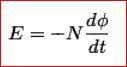
Lenz'slawstatesthatwhenanemfisgeneratedbyachange inmagneticfluxaccordingtoFaraday'sLaw,thepolarityof the induced emf is such, that it produces ancurrentthat'smagneticfieldopposesthechangewhich produces it. The negative sign used inFaraday's law of electromagneticinduction,indicatesthattheinducedemf(ε ) and the change inmagnetic flux( δΦB ) have opposite signs. ConsideringLenz's Law
Reasonforopposing,causeofcurrentsaccordingtoLenz’s Law-
Lenz'slawobeysthelawofconservationofenergy and if the direction of the magnetic fieldthat creates thecurrentand themagnetic fieldof thecurrentin a conductor are in samedirection, thenthese twomagnetic fields would add up and produce thecurrentof twice the magnitude and this would in turn create moremagnetic field, which will cause more currentand this process continuing on and on leads to violation of the law of conservation of energy. If the inducedcurrentcreates amagneticfieldwhichisequalandoppositetothedirection ofmagneticfieldthatcreatesit,thenonlyitcanresistthe change in themagnetic fieldin the area, which is in accordancetotheNewton'sthirdlawofmotion.
Conventional wind generators suffer from a number of disadvantages.Onesuchdisadvantageisthatthemajorityof suchgeneratorsutilizeironcorestators.Apartfromthehigh cost associated with iron cores, they are also heavy and requireadditionalresourcesandsupporttoinstall,stabilize and maintain. Iron core stators also suffer from cogging torque, which isthetorque resultingfrom the interaction betweenthepermanentmagnetsoftherotorandthestator slots of a PM machine. It is also known as detent or "nocurrent" torque. Cogging torque is an undesirable component for the operation of iron-core electric generators.Itisespeciallyprominentatlowerspeedsand manifestsitselfinstutteredrotation.
Afurtherdisadvantageofconventionalwindgeneratorsis the cost associated with their repair and maintenance. In
International Research Journal of Engineering and Technology (IRJET) e-ISSN: 2395-0056
Volume: 11 Issue: 04 | Apr 2024 www.irjet.net p-ISSN: 2395-0072
particular, where windings on either the rotor or stator become worn or defective, highly skilled technicians are requiredtoconductrepairormaintenance.Theweightand unwieldiness of conventional iron-core stators also often require the use of machinery or teams of technicians to conductevenroutinemaintenance.
6.1 Advantages of permanent magnets:
Permanent magnet excited machines have a series of economic and technical advantages over the electrically excitedtype.Someoftheseadvantagescanbesummarized asfollows:
a) No additional power supply for the magnet field excitation.
b)Improvementintheefficiencyandthermalcharacteristics ofthemotorduetoabsenceofthefieldlosses.
c) Higher reliability due to absence of mechanical componentse.g.sliprings.
Higherpowertoweightratio.Permanent-magnetmachines allowagreatdealofflexibilityintheirgeometry.Basedon the direction of flux penetration, permanent magnet machines can be classified as: radial flux, Axial-flux and transversal-fluxmachines.
6.2 Advantages of a radial flux machine:
Thepermanentmagnetsofradial-fluxmachinesareradially oriented. Radial-flux Permanent-magnet machines can be dividedmainlyintotwotypes,surface-magnetandBuriedmagnetmachines.Thesimplewayofconstructingtherotor with high number of poles is by gluing the permanent magnetsontherotorsurfaceofthemachine.
Theproperselectionofmaterialforthedifferentpartofa machineisthemainobjectiveinthefabricationofmachine. Foradesignengineeritismustthathebefamiliarwiththe effect,whichthemanufacturingprocessandheattreatment haveonthepropertiesofmaterials.TheChoiceofmaterial for engineering purposes depends upon the following factors:
Availabilityofthematerials.
Suitability of materials for the working condition in service.
Thecostofmaterials.
Physicalandchemicalpropertiesofmaterial.
Mechanicalpropertiesofmaterial.
Inengineeringpractice,themachinepartsaresubjectedto variousforces,whichmaybeduetoeitheroneormoreof thefollowing.
1.Energytransmitted
2.Weightofmachine
3.Frictionalresistance
4.Inertiaofreciprocatingparts
5.Changeoftemperature
The selection of the materials depends upon the various types of stresses that are set up during operation. The materialselectedshouldwithstandit.Anothercriteriafor selectionofmetaldependuponthetypeofloadbecausea machinepartresistloadmoreeasilythanaliveloadandlive loadmoreeasilythanashockload.
Selection of the material depends upon factor of safety, whichinturndependsuponthefollowingfactors.
1. Reliabilitiesofproperties
2. Reliabilityofappliedload
3. Thecertaintyastoexactmodeoffailure
4. Theextentofsimplifyingassumptions
5. Theextentoflocalized
6. The extent of initial stresses set up during manufacturing
7. Theextentlossoflifeiffailureoccurs
8. Theextentoflossofpropertyiffailureoccurs.
9. ForBaseplate,motorsupport,sleeveandshaftMaterial usedis Mild steel.
This paper provides an overview by comparing the advantages and disadvantages of different types of wind turbine generators including DC, synchronous and asynchronouswindturbinegenerators.Ifthewindturbine generators have to be further improved, especially the calculation-Morein-depthanalysisinwindturbinedesign, controlandoperationusingresearchandtestingmethodsis essentialbutdespitecontinuousresearchanddevelopment efforts, wind power systems still face technological, environmentalissueshasfacedmanyfinancialchallenges. In summary, there may not be an optimal wind turbine generatortechnologytotickalltheboxes.Theselectionof complex wind turbine systems is highly dependent on capital and operating costs because wind markets are particularlycost-sensitiveEssentially,thedecisionalways comesdowntocomparingmaterialcoststolandsittingexist between magnets, superconductors, copper, iron or other reactivematerials.
We are developing a special generator that can also operate at lower torque so if the wind speed is 2m/s our turbine will generate power so that we can use it at lower speeds as well.
[1] Abo-Khalil,A.G.(2011).Anewwindturbinesimulator usingasquirrel-cagemotorforwindpowergeneration
International Research Journal of Engineering and Technology (IRJET) e-ISSN: 2395-0056
Volume: 11 Issue: 04 | Apr 2024 www.irjet.net p-ISSN: 2395-0072
systems.IEEENinthInternationalConferenceonPower Electronics and Drive Systems (PEDS), 750-755.M. Young, The Technical Writer’s Handbook. Mill Valley, CA:UniversityScience,1989.
[2] Al-Majed, S. I., & Fujigaki, T. (2010). Wind power generation:Anoverview.TheInter‐nationalSymposium on Modern Electric Power Systems (MEPS), 1-6. K. Elissa,“Titleofpaperifknown,”unpublished.
[3] Aly, H. H., & El -Hawary, M. E. (2010). An overview of offshorewindelectricenergyresources.23rdCanadian Conference on Electrical and Computer Engineering CCECE,1-8.
[4] Bansal, R. C., Zobaa, A. F., & Saket, R. K. (2005). Some issuesrelatedtopowergenerationusingwindenergy conversionsystems:anoverview.Int.J.EmergingElectr PowerSyst.,3(2),Article1070.
[5] AbrahamsenAB,MijatovicN,SeilerE,TrholtC,Norgard P, Pedersen N, Andersen N and Ostergard J 2010 SupercondSci.Technol.23034019.
[6] Windinpower2015EuropeanstatisticsEWEA.