
International Research Journal of Engineering and Technology (IRJET) e-ISSN: 2395-0056
Volume: 11 Issue: 04 | Apr 2024 www.irjet.net p-ISSN: 2395-0072
International Research Journal of Engineering and Technology (IRJET) e-ISSN: 2395-0056
Volume: 11 Issue: 04 | Apr 2024 www.irjet.net p-ISSN: 2395-0072
Diksha Sagar1 , Dr. Jeeru Dinesh Reddy2
1PG Student, Dept. of Electronics and Communication Engineering, BMS College of Engineering, Bengaluru, India
2Professor, Dept. of Electronics and Communication Engineering, BMS College of Engineering, Bengaluru, India
Abstract - Reaching high integration, high speed, high resolution, and high reliability is the aim of image preprocessing systems. Image processing systems are widely employed in both the military and commercial industries. Image processing technology-based object detection has drawn a lot of interest in the military because of its noncontact capabilities, capacity to hide, and ability to avoid interference. In the business sector, it is widely used in industrial detection systems and machine vision. There are threemainkindsofimageprocessingsystemsthatareusedto implement digital image processing techniques. The three main chips that comprise each system are the FPGA (Field Programmable Gate Array), DSP (Digital Signal Processor chip), and ASIC (Application Specific Integrated Circuit). In this work, we created an image processing system based on FPGA. The system can take samples from the data stream.
Key Words: FPGA, Image acquisition system, Image processing,XilinxVivadoHLS,MATLAB,Verilog.
Artificial intelligence, pattern recognition, and signal processingareallengagedinthestudyofpicturecollection andprocessing,whichhasbeenapopularareaofresearch. This technology is mainly used in automotive electronics, consumerelectronics,securitymonitoring,nationaldefence, andotherfieldsof3Dprojection.Theincreasingpopularity ofdigitalimageprocessingtechnologyisinseparablefrom theperfectingofprocessingsystems.Intheimageprocessing system, the key technology is real-time image acquisition andprocessing.Meanwhile,thespeedandqualityofimage acquisitiondirectlyaffectthesystem[10].Theadvancement of large-scale integrated circuit fabrication technologies, particularly FPGA, and microelectronics has produced innovative concepts and techniques for enhancing the functionality of image processing systems in recent years. The image processing system based on FPGA is widely utilizedintheimagepreprocessingareabecauseofthevast amountofdataandrapidprocessingspeedrequiredforlowlevelpicturepreprocessing.Theneedforvideoinformation has increased as a result of the advancements made in multimedia technologies in recent years. In any case, the significanceofpictureprocessingandcaptureisgrowing.8bit standard RGB (sRGB) pictures, which are commonly compressed using the JPEG standard, make up the great majority of images used in computer vision and image processingapplications.Theprocessesofalmostallimaging
applicationssupportJPEGandsRGBpictureformats.These days,themajorityofcamerasenablethesavingofphotosin RAW format, which is an unprocessed, minimally compressedpictureformatthatcapturesthereactionfrom thecamerasensor.MorebenefitsofRAWoversRGBinclude abroadercolorgamut,ahigherdynamicrange(usually12–14bits),andalinearresponsetosceneradiance.Forseveral computer vision applications, including white balance, photometricstereo,picturerestoration,andmore,RAWis preferred.PhotographersalsopreferRAWbecauseitgives them more versatility when manipulating images in postprocessing The serial process of compression of images starts with the conversion of an RGB image into YIQ if required.TheresultingimageisthentransformedbyDCT.In the quantization, unnecessary data about the image is eliminatedfromsizeandquality. Encodingoftheimage is doneforprotectionbychangingthenamesofthevaluesof thequantizedimagebypassingtheimageintothechannel encoder. The image is involved in inverse quantization, which retrieves the lost data from the image. Passing throughtheinversetransformationphaseformstheoriginal image. Image compression is a technique that lowers the amountofdata neededtocommunicatewithanadvanced image.Andeliminatingtheredundantworkerswillprovide this.
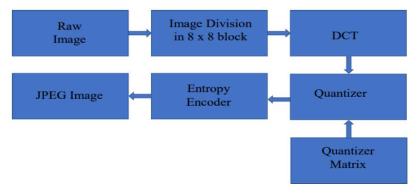
The first operation of the JPEG Encoder core is converting the red, green, and blue pixel values to their correspondingLuminanceandChrominance(Y,Cb,andCr) values. TheRGB2YCBCRmoduleiswherethisprocedureis carried out. The operation is based on the following formulas:
Y=.299*Red + .587*Green + .114*Blue
Cb=-.1687*Red + -.3313*Green +.5*Blue+128
Cr=.5*Red + -.4187*Green + -.0813*Blue+128
Fixedpointmultiplications areusedtocarryoutthese tasks. Alloftheconstantvaluesintheabove3x3matrixare multipliedby2^14(16384). Oneclockcycleisusedforthe multiplications,andthenextclockcycleisusedtoaddthe sumoftheproducts.Inordertoobtainaquick
International Research Journal of Engineering and Technology (IRJET) e-ISSN: 2395-0056
Volume: 11 Issue: 04 | Apr 2024 www.irjet.net p-ISSN: 2395-0072
clockfrequencyduringsynthesis,thisisdone.Next,rather thanreallydividingthesums,thesumsaredividedby2^14, whichisaccomplishedbythrowingawaythe14LSBsofthe sumvalues.Whenrounding,the13thLSBisexamined,andif itis1,1isaddedtothetotal.
ThenextstepaftercalculatingtheY,Cb,andCrvaluesis performing the Discrete Cosine Transform (DCT). This is commonlyreferredtoasa2DDCT. Theactualformulaisthe following:
DY=T*Y*inv(T)
TistheDCTmatrix. YisthematrixofYvaluesforthe 8x8imageblock. DYistheresultantmatrixafterthe2DDCT. TheDCTneedstobeperformedseparatelyontheY,Cb,and Cr values for each block. The DCT of the Y values is performed in the y_dct module. The cb_dct and cr_dct modulescontaintheDCToftheCbandCrvalues.Sincethe cb_dct and cr_dct modules are nearly identical, I will just discussthey_dctmoduleinthissection.
NowyoumayhavenoticedthatIhavenotcenteredtheY, Cb,andCrvalueson0intheprevious stage. Todothat,I wouldhavesubtracted128fromthefinalYvalue,andnot addedthe128tothefinalCband Crvalues. Toperformthe DCT,thevaluesofY,Cb,andCrneedtobecenteredaround0 and in the range –128 to 127. However, I perform a few tricksintheDCTmodulethatallowmetokeeptheY,Cb,and Crvaluesintherangefrom0-255. Idothisbecauseitmakes theimplementationoftheDCTeasier
The DCT matrix, or T as I call it, is multiplied by the constantvalue16384or2^14. TherowsoftheTmatrixare orthonormal(theentriesineachrowaddupto0),exceptfor thefirstrow. Becausetherows2-8areorthonormal,itdoes not matter that I have not centered the Y values on 0. I performthemultiplicationoftheTrowsbytheYcolumnsof data,andtheextra128ineachoftheYvaluesiscancelled outbytheorthonormalTrows. Thefirstrow,however,is notorthonormal-ithasaconstantvalueof.3536,or5793 afteritismultipliedby2^14. SinceIhavenotcenteredYby 0, the extra 128 in each value will result in an extra 128*8*5793=5932032inthefinalsum. Sotomakeupfor thefactthatIhavenotcenteredtheYvalueson0,Isubtract 5932032fromtheresultofthefirstrowofTmultipliedby eachofthe8columnsoftheYmatrix. Ifyouthinkaboutthis, itmeansIhaveto perform a total of8subtractionsfor an 8x8matrixofYvalues.IfIhadsubtracted128fromeachY value before the DCT module, I would have needed to performatotalof64subtractions.
After multiplying the T matrix by the Y matrix, the resultingmatrixismultipliedbytheinverseoftheTmatrix. Inordertomaximizetheclockfrequencyforthedesign,this procedureiscarriedoutinthecode. Theresultisthecode
may look overly confusing, but I tried many different schemesbeforesettlingontheoneusedinthecode. Iwould simulate the code, make sure it functioned, and then synthesizetoseewhatclockspeedIcouldget.Ikeptdoing thisuntilIeventuallyfoundtheoptimalclockspeed,which was about 300 MHz. I targeted a Xilinx Virtex 5 FPGA to achievethisspeed.
The next step is fairly straightforward. The module y_quantizer comes next for the Y values. The Cb and Cr values go through the cb_quantizer and cr_quantizer modules. The 64 quantization values are stored in the parametersQ1_1throughQ8_8. Iusedfinalsvaluesof1for my core, but you could change these values to any quantizationyou want. Isimulateddifferent quantization values during testing, and I settled on values of 1, correspondingtoQ=100,becausethisstressedmycodethe mostandIwastryingtobreakthecoreinmyfinaltesting. Thecoredidnotbreak,itworked,butIleftthequantization valuesastheywere.
Asinpreviousstages,Iavoidperformingactualdivision asthiswouldbeanunnecessaryandburdensomecalculation toperform. IcreateotherparametersQQ1_1throughQQ8_8, andeachvalueis4096dividedbyQ1_1throughQ8_8. For example,QQ1_1=4096/Q1_1. Thisdivisionisperformed whenthecodeiscompiled,soitdoesn’trequiredivisionin theFPGA.
Theinputvaluesaremultipliedbytheircorresponding parametervalues,QQ1_1throughQQ8_8. Then,thebottom 12 bits are chopped off the product. This gets rid of the 4096,or2^12,thatwasusedtocreatetheparametersQQ1_1 throughQQ8_8. Thefinalvaluesareroundedbasedonthe valueinthe11th LSB.
Themoduley_huffperformstheHuffmanencodingofthe quantized Yvaluescoming outof the y_quantizermodule. The modules cb_huff and cr_huff perform the Huffman encoding for the Cb and Cr values. The module yd_q_h combinesthey_dct,y_quantizer,andy_huff modules. The valuesfromy_quantizeraretransposed(rowsswappedwith columns) as they are input to the y_huff module. This is donesothattheinputsofeach8x8blocktothetopmodule, jpeg_top,canbewritteninthetraditionallefttorightorder. PeformingtheDCTrequiresmatrixmultiplication,andthe rowsoftheTmatrixaremultipliedbythecolumnsoftheY matrix. So the Y values would need to be entered in a column format, from top to bottom, to implement this. Instead,theYvaluescanbeenteredinthetraditionalrow format,fromlefttoright,andthenbytransposingthevalues astheypassbetweenthey_quantizerandy_huff modules, theproperorganizationofYvaluesisregained.
International Research Journal of Engineering and Technology (IRJET) e-ISSN: 2395-0056
Volume: 11 Issue: 04 | Apr 2024 www.irjet.net p-ISSN: 2395-0072
The Huffman table can be changed by changing the values in this module – the specific lines of code with the Huffmantablearelines1407-1930. However,thecoredoes notallowtheHuffmantabletobechangedonthefly. You willhavetorecompilethecodetochangetheHuffmantable. Youshouldcreatea full Huffmantable, even ifyou have a smallimagefileanddonotexpecttousealloftheHuffman codes. Thecalculationsinthiscoremaydifferslightlyfrom howyoudoyourcalculations,andifyouuseaHuffmantable withoutallofthepossiblevaluesdefined,thecoremayneed aHuffmancodethatisnotstoredintheRAM,andtheresult willbeanincorrectbitstreamoutput.
The DC component is calculated first, then the AC componentsarecalculatedinzigzagorder. Theoutputfrom they_huffmoduleisa32-bitssignalcontainingtheHuffman codesandamplitudesfortheYvalues.
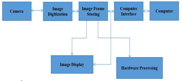
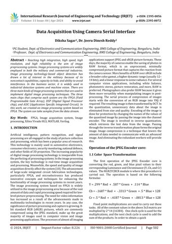
Fig 1. Block Diagram of the Entire Camera Serial Interface[10]
The procedure for taking and processing a picture is shown in the block diagram. The process starts with the image capture phase, which gathers visual data. The acquired image is next subjected to Digital Conversion, whichconvertsitintoaformatthatmaybealtereddigitally. The digitally converted image finds temporary refuge inTemporaryStoragebeforeprogressingtotheComputer Interface.Thisinterfacefacilitatescommunicationbetween thecomputersystemandimagingdevices.Thecrucialstage ofimageprocessingcomesnext,wherethedigitalpictureis altered by applying adjustments, improvements, or other changes.Atthisjuncture,twodivergentpathsemerge:
1) Display Output: In this case, consumers may see the finished product by viewing the processed image on a screen.
2) Hardware Processing: As an alternative, further hardware-level adjustments or examinations of the image maybeperformed.
The workflow from taking a picture to showing the processed result is represented by this paradigm, where each block stands for a critical stage in the entire digital imageprocessingprocess.
1) Raw Image:
ThestartingpointofourjourneyistheRawImage.This represents the unprocessed visual data captured by a cameraorimagingdevice.It’sakintotheuntouchedcanvas awaitingtransformation.
2) Compression:
Our next stop is theCompressionstage. Here, the raw image undergoes a crucial process. Imagine it as a digital wardrobe organizer compressing bulky files without compromising quality. Compression reduces the file size, makingitmoremanageableforstorageandtransmission.
3) Memory:
Finally,ourtransformedimagefindsitshomeinMemory. Thinkofthisasadigitalattic aplacewheredataresides temporarily.Whetherit’sRAM,harddrives,orcloudstorage, memoryholdsourcompressedimageuntilfurtheractionis taken.
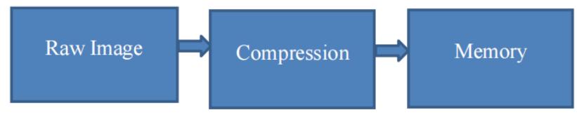
Image Compression:
2.1 Raw Image:
The procedure starts with a raw picture, which is an array of two-dimensional pixel values that represent the colorandintensityinformationoftheimage.
The raw image is divided into non-overlapping 8x8 blocks.These blocksareindependentunitsfor processing andanalysis.
International Research Journal of Engineering and Technology (IRJET) e-ISSN: 2395-0056
Volume: 11 Issue: 04 | Apr 2024 www.irjet.net p-ISSN: 2395-0072
Each 8x8 block is then subjected to a mathematical transformationcalledtheDiscreteCosineTransform(DCT). TheDCTconvertsthespatialinformationoftheblockinto frequencyinformation.Itrepresentstheimagedatainterms ofdifferentfrequencycomponents.
After the DCT, the resulting frequency coefficients are quantized. Quantization reduces the precision of the coefficientsbydividingthembyasetofquantizationvalues. This process discards high-frequency components and preserves the low-frequency components, allowing for significantcompression.
Thenextstepistocompressthequantizedcoefficients using an entropy encoding technique (usually Huffman coding).Byusingthestatisticalcharacteristicsofthedata, entropy encoding assigns longer codes to less frequent coefficientsandshortercodestomoreoftenoccurringones. Thisfurtherreducestheoverallsizeoftheencodeddata.
Finally,theentropy-encodeddataiscombinedwiththe necessaryheaderinformationtoformthecompressedJPEG imagefile.TheresultingJPEGimageconsistsofaseriesof compressed blocks, each containing the encoded and quantizedcoefficients,alongwiththenecessaryinformation fordecodinganddisplayingtheimage.
Itenablesareliablecostofsavingsthatisincludedwith the sending of less data on the network of switched telephones,inwhichthecostofacallisnormallydependent onitsduration.Itisnotonlytodecreasetherequirementsof storagebutalsotodecreasetheentiretimeofexecution.It decreasesthechancesoftheerror’stransmission.Itenables alevelofsecurityagainstmonitoringunlawfulactivities.
JPEG Process:
1.Dividingtheimageinto8by8blocksisthefirststagein thecompressionprocess.
2.Whilethebreakingisdone,wemustapplytheDCTtoeach image.
3.Therefore,byquantizationeachblockisgetcompressed.
4.Thearrayofcompressedblocksthatconstitutetheimage getsstoredbydrasticallyreducedamountofspace.
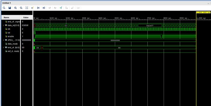
Thetop-levelmodule,jpeg_top,managesaJPEGencoding core with minimal inputs: clock, enable, and reset lines. Whentheinitialpixel'sdataisreadyandstayshighduring each8x8pixelblock's64-clockcycleinput,theenablesignal is triggered. Following this input phase, there is no more data received for the minimum 33 clock cycles that the enablesignalremainshigh.Theenablesignalisthenquickly loweredforoneclockcycleandthenraisedonceagainfor thesubsequent8x8blockinput.Red,green,andbluepixel valuesarestoredonthe24-bitdatabus,withbluestoredin bits[23:16],greeninbits[15:8],andredinbits[7:0].Atthe firstclockcycleofthelast8x8block,theend_of_file_signal getshigh,signalingthatallofthebitsinthisfinalblockmust beproduced.Thebitstreamismanagedviathe32-bitoutput bus.
The JPEG bitstream is output via the 32-bit bus signal JPEG_bitstream. The first eight bits are located at [31:24], followed by the following eight bits at [23:16], and so on. When the data_ready signal is high, the data in the JPEG bitstreamislegitimate.Tosignalgenuinedata,data_ready will only be high for a single clock cycle. The signal eof_data_partial_readywillbehighforoneclockcyclewhen theadditional bitsare inthesignal JPEG_bitstreamon the lastblockofdataifthelastbitsdonotfillthe32-bitbus.The end_of_file_bitstream_count5-bitsignalindicateshowmany additionalbitsthereare.
A commonly used image contains redundant information because of neighbouring pixels, which are correlated and containredundantinformation.Themainobjectiveofimage compressionistoremoveredundanciesfromanimageby removing them as much as possible while keeping the resolution and visual quality of the compressed image as close as possible to the original image. Compression is further divided into predictive and transform coding. Transformcodingmeansthatalargeamountofinformation istransferredintoaverysmallnumberofblocks.Oneofthe best examples of a transformed coding technique is the wavelettransform.Predictivemeans,basedonthetraining set(neighbours),reducesomeredundancies.Context-based compressionalgorithmsareusedaspredictivetechniques.
UsingVerilogcode,thesuggestedblockdiagramwasput intopracticeinhardware.TheXilinxVivado2018.2version tool was used to simulate the hardware, and an RTL schematicforthe design wasproduced. The XilinxVivado 2018.2versiontoolwasalsoutilizedforthesynthesisofthe design blocks. A C specification may be converted into a registertransferlevel(RTL)implementationusingtheXilinx VivadoHigh-LevelSynthesis(HLS)tool,whichcanthenbe
International Research Journal of Engineering and Technology (IRJET) e-ISSN: 2395-0056
Volume: 11 Issue: 04 | Apr 2024 www.irjet.net p-ISSN: 2395-0072
synthesized into a Xilinx field programmable gate array (FPGA).WiththeFPGA,youmaycreateCspecificationsinC, C++,SystemC,orasanAPICkernelfortheOpenComputing Language (OpenCL). Its massively parallel design offers advantagesovertraditional processorsintermsofpower, cost,andperformance.HLSmakesitpossiblebyaimingfor an FPGA as the execution fabric. This allows the implementation of computationally intensive software algorithms into actual products, not just functionality demonstrators.
3.1 Software Simulation Results
Huffman Image Compression :
1) Original Image:
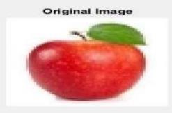
4. Original Image
Theoriginalimage'sdetailsareasfollows:
Imagesize :1.45KB
Dimensions :225x225
Width :225pixels
Height :225pixels
HorizontalResolution :Nil
VerticalResolution :Nil
BitDepth :Nil
FocalLength :Nil
2) Compressed Image:
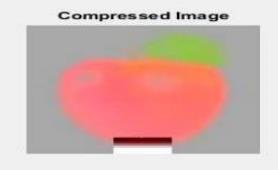
Fig 4. Compressed Image
Thecompressed image'sdetailsareasfollows:
Imagesize :0.90KB
Dimensions :64x64
Width :64pixels
Height :64pixels
HorizontalResolution :96dpi
VerticalResolution :96dpi
BitDepth :24
FocalLength :35mm
AsimilarsimulationisdoneforthecolouredimageinFig. 7. using the same Huffman image compression code. It is clearfromthecomparisonphotosthatthe1.45kboriginal imagehasbeenshrunkto0.90kb.
3.2 Hardware RTL Schematics, Simulation and Synthesis Results
1) RTL Schematic of the Proposed Block Diagram
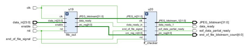
Fig 7. RTL Schematic of The Proposed Block Diagram
International Research Journal of Engineering and Technology (IRJET) e-ISSN: 2395-0056
Volume: 11 Issue: 04 | Apr 2024 www.irjet.net p-ISSN: 2395-0072
2) Simulation Result
3) Synthesis Result
The design blocks were synthesised using the Xilinx Vivado2018.2Hlxtool.Aresourceutilisationtableisalso givenbelow.
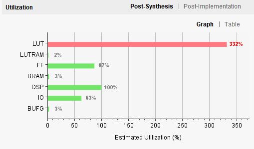
Fig 10. Resource Utilisation Graph
Table -1
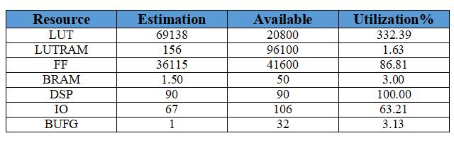
Fig 11. Resource Utilisation Table
4. CONCLUSIONS
WeproposedanefficientmethodtoprocessJPEGimagesby converting them to grayscale and then to PNG using MATLAB. Image compression reduces memory usage. Identifyingdatapatternsiscrucialforeffectivecompression. Implementing image processing on an FPGA involves systematicsteps,includingcameraselection,FPGAchoice, and HDL programming. The FPGA synthesis and implementation processes, along with configuration and
testing,arecrucialforensuringthesuccessfulintegrationof thedesignedsystem.
[1] Xin Liu, Ling Li, “ FPGA-based Three- dimensional endoscope system using a single CCD camera,” IEEE, 2015.
[2] B.A.S.A. Thilakaratne, W.A.S. Wijesinghe, “FPGA Based Camera Interface For Real Time Video Processing,” 2015.
[3] Sanjay Kumar Gupta, “An Algorithm For Image Compression Using Huffman Coding Techniques,” IJARSE,Vol.No.5,IssueNo.07,July2016.
[4] Shammi Rahangdale, Paul Keijzer, P.Kruit, “MBSEM Image Acquisition and Image Processing in Lab View FPGA,” IWSSIP,2016.
[5] Ravi B. Humane, Prof. A. R. Askhedkar, “ Sensors InterfacingonRe-configurablePlatformusingFPGAin IoTenvironment,“IJIRSET,Vol.5,Issue9,Sepetember 2016.
[6] WANG Rong-yang, Lu Bo, Qian Zhen-hue, “Real-time MechanicalParkingEquipmentImageAcquisitionand PreprocessingBasedonFPGA,” ICCA,2016.
[7] S.M. Dominguez-Nicolas, P. Argiielles-Lucho, P.Wiederhold, “FPGA based image acquisition and graphic interface for hardness tests by indentation,” ISSN,2016.
[8] Ms. Sonal R. Lad1, Prof. P.C. Bhaskar2, “Acquisition BoardDesignBasedonArmandFPGAforImageData,” IJIREEICE,Vol.4,issue6,June2016.
[9] Naga Raju Boyal, Vijay Kumar Jindel, Bala Venkateswarlu Avvaru2, Sreelekha Kande3 and RamanjappaThogata,“DesignandDevelopmentofFPGA BasedImageAcquisitionSystem,” ISSN,2017.
[10] RuiLu1,XiaohuiLiu1,XiaodanWang2,JinPan1,Kuangyi Sun1 and Hellen Waynes, “The Design of FPGA-based Digital Image Processing System and Research on Algorithms,” ISSN: 2233-7857 Vol. 10, No.2, IJFGCN, 2017.
[11] Rang M.H. Nguyen1, Michael S. Brown, “RAW Image ReconstructionUsingaSelf-containedsRGB-JPEGImage withSmallMemoryOverhead,” Springer,2017.
[12] Himanshu Shekhar1, Hitesh Pant2, Ritanshu Tyagi3, Abhigyan Singh4, “Huffman Coding Based Lossless ImageCompression,“IJARIIE-ISSN(O),Vol.No.4,Issue 05,2018.
International Research Journal of Engineering and Technology (IRJET) e-ISSN: 2395-0056
Volume: 11 Issue: 04 | Apr 2024 www.irjet.net p-ISSN: 2395-0072
[13] Hao Wang, Zhi Weng, Yan Li, “Design of high-speed imageacquisitionsystembasedonFPGA,” IEEE,2018.
[14] Si Yong Fu, “Design of High Speed Data Acqusition System for Linear Array CCD Based on FPGA,” ICMIR, 2019.
[15] V.R.Balaji1, J.Sathiya Priya, J.R.Dinesh Kumar, “FPGA Implementation of Image Acquisition in Marine Environment,” ISSN:0973-2667Vol.No.13,Number2, 2019.
[16] Rohit Raj1, Navneet Singh2, “A Review-FPGA based Architectures for Image Capturing Consequently Processing and Display using VGA Monitor,” IRJET Volume07,issue01,Jan2020.
[17] Prashant Kharat, Vaibhav Mapari, Dr. Amol Bhatkar, “DigitalCameraDeactivationByUsingIRBasedImage ProcessingTechnique,” IJSRST Vol.5,issue6,2020.
[18] SharanReddyAyiluril,SampathKumarYelchuri2,Vusa Laxumudu3, Gorrepati Praveeen Sajan4, Arvapalli Yaswanth Pavan Kumar5, Kulraj Kaur6, “JPEG Image Compression Using MATLAB,” www.irjmrts.com, Vol. No.3,IssueNo.05,May2021.
[19] AleksanderMielczarek1,DariuszRadoslawMakowski1, ChristopherGerth2,BerndSteffen2,MicheleCaselle3 andLorenzoRota33,4,“Real-TimeDataAcquisitionand Processing System for MHz Repetition Rate Image Sensors,” MDPI,2021.
[20] EduardoMagdaleno1,ManuelRodriguezValido1,David Hernandez2,3,MariaBalaguer4,BasilioRuizCobo2,3 and David Diaz 1, “FPGA Implementation of Image Ordering and Parking Algorithm for TuMag Camera,” MDPI,2021.
[21] https://www.xilinx.com/support/documentationnavigation/design hubs/dh0012-vivado-high-levelsynthesis-hub.html.
2024, IRJET | Impact Factor value: 8.226 |