
International Research Journal of Engineering and Technology (IRJET) e-ISSN: 2395-0056
Volume: 11 Issue: 04 | Apr 2024 www.irjet.net p-ISSN: 2395-0072
International Research Journal of Engineering and Technology (IRJET) e-ISSN: 2395-0056
Volume: 11 Issue: 04 | Apr 2024 www.irjet.net p-ISSN: 2395-0072
Srushti P. Bochare1 , Ashvini G. Feran2 , Shraddha S. Naswale3 , Pallavi S. Satao4 , Mrs. Nanda Y. Mhaisagar5
1Student of Electronics and Telecommunication, Mauli College of Engineering and Technology, Shegaon444203(Maharashtra)India
2Student of Electronics and Telecommunication, Mauli College of Engineering and Technology, Shegaon444203(Maharashtra)India
3Student of Electronics and Telecommunication, Mauli College of Engineering and Technology, Shegaon444203(Maharashtra)India
4Student of Electronics and Telecommunication, Mauli College of Engineering and Technology, Shegaon444203(Maharashtra)India
5 Assistant Professor at Electronic and Telecommunication, Mauli College of Engineering and Technology ,Shegaon444203(Maharashtra) India
Abstract – This research presents an innovative approachto enhance roadsafetywiththedevelopment of an Internet of Things (IoT)-based Vehicle Accident Detection and Live Tracking System. The system utilizes the ESP32 microcontroller, Firebase cloud platform, tilt sensor, and a 3-axis sensor for real-time detection and response to vehicular accidents. The ESP32 microcontroller acts as the central processing unit, seamlesslyintegratingwithboththetiltsensorandthe 3axis sensor. The tilt sensor detects sudden changes in the vehicle'sorientation,indicatingapotentialaccident,while the 3-axis sensor captures acceleration and deceleration data for precise accident detection. When a potential accident is detected, the system initiates immediate live tracking through the Firebase cloud platform. Firebase enablesreal-timecommunicationbetweenthevehicleand a designated monitoring center, facilitating swift emergencyresponsemeasures.UtilizingFirebase'srobust features ensures the security and integrity of sensitive information. The livetrackingfeature enablesauthorities to monitor the vehicle's location and condition in realtime, enabling prompt intervention and assistance, thereby reducing emergency response times and improving road safety. Implementation of this IoT-based system has the potential to revolutionize accident detection and response mechanisms, creating a safer transportation environment. The combination of ESP32, Firebase,tiltsensor, and 3-axissensortechnologies offers arobustandscalablesolutionformitigatingtheimpactof vehicularaccidentsonbothlivesandproperty
Key Words: 16X2 lcd display, 3axis accelerometer sensor, vibration sensor, GPS module, Motor driver module, motor, speed sensor, ESP32
The Internet of Things (IoT) has emerged as a transformative technology, revolutionizing the way we connect and interact with the world around us. By interconnecting embedded computing devices within the existing internet infrastructure, IoT offers unparalleled levels of connectivity, enabling seamless communication between devices, systems, and services. This connectivity extends far beyond traditional machine-to-machine (M2M) communications, encompassing a diverse range of protocols, domains, and applications. In virtually every field of automation, IoT has paved the way for innovative solutions and advanced applications, unlocking new possibilities for efficiency, productivity, and convenience. From optimizing energy distribution through Smart Grids to revolutionizing healthcare with heart monitoring implants, IoT has become an integral part of modern life. One particularly promising application of IoT technology liesintherealmofvehiclesafety.Withtheproliferationof smartobjectsandembeddedsensors,itisnowpossibleto develop sophisticated systems for accident detection and tracking. Our project, "IoT BASED VEHICLE ACCIDENT DETECTION AND TRACKING SYSTEM USING GPS MODEM," represents a pioneering effort in this domain, leveraging IoT principles to enhance road safety and emergency response capabilities. At the heart of our system is the NODE MCU, serving as the central hub for communication and coordination. When activated, the system provides a visual indication of power supply through an LED indicator, signalling its readiness to Vibrationsensorsplayacrucialroleinaccidentdetection, promptly sensing obstacles or collisions and triggering interrupts to the Raspberry Pi. This real-time data is then processed and analysed, facilitating swift and accurate decision-makinginresponsetoemergencies. Meanwhile, theGPSmodemenablespreciselocationtracking,allowing
International Research Journal of Engineering and Technology (IRJET) e-ISSN: 2395-0056
Volume: 11 Issue: 04 | Apr 2024 www.irjet.net p-ISSN: 2395-0072
ustopinpointtheexactcoordinatesofvehiclesinvolvedin accidents. This information is seamlessly relayed to a dedicated mobile application via the internet, providing users with vital insights into the location and severity of incidents. Byharnessing the power ofIoTtechnology,our system not only detects accidents but also empowers stakeholders with actionable data for effective response and mitigation efforts. Through modulation and demodulation, the modem ensures reliable communication,enablingseamlesstransmissionofcritical information in real-time. As we delve deeper into the details of our project, we aim to shed light on the transformativepotentialofIoTinenhancingvehiclesafety and revolutionizing emergency response systems. With a focusoninnovationandefficiency,westrivetocontribute toasafer,moreconnectedfutureforall.
1.1 Block Diagram
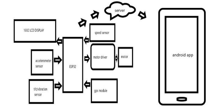
Fig1.1 : Block Diagram
At the center of the block diagram is the ESP32 microcontroller, which serves as the brain of the system. The ESP32 is connected to several different sensors and modules, including the LCD display, GPS module, accelerometer sensor, tilt vibration sensor, speed sensor, andmotordriver,aswellasaWIFImoduleforconnecting to the internet. The LCD display is used to show sensor valuesinreal-time,making iteasyfortheusertomonitor the system's performance. The ESP32 communicates with theLCDdisplayusingaserialinterface,sendingdatatobe displayed on the screen. The GPS module is used to determine the system's location, providing coordinates thatcanbeusedfornavigationorotherpurposes.TheGPS module communicates with the ESP32 over a serial interface, sending data about the system's location. The accelerometer sensor is used to measure the system's acceleration and tilt, providing data that can be used to control the system's movement. The accelerometer communicates with the ESP32 using an analog interface, sendingdataaboutthesystem'saccelerationandtilt.
Thetiltvibrationsensorisusedtodetectvibrationsinthe system, providing data that can be used to monitor the system's stability. The tilt vibration sensor communicates with the ESP32 using an analog interface, sending data aboutthesystem'svibrations.Thespeedsensorisusedto
calculate the speed of the motor, providing data that can be used to control the motor's speed. The speed sensor communicates with the ESP32 using a digital interface, sendingdataaboutthemotor'sspeed.Themotordriveris usedtocontrolthemotor'sspeedanddirection,providing power to the motor when necessary. The motor driver communicates with the ESP32 using a digital interface, receiving commands to control the motor's speed and direction.TheFirebaseserverisusedtostoreandretrieve data from the system. The ESP32 communicates with the Firebase server using the Firebase API over Wi-Fi___33. The ESP32 sends sensor data to the Firebase server, where it's stored for later retrieval. An application can be developedthatretrievesthedatafromtheFirebaseserver and displays it to the user. Overall, this block diagram illustrates a system that's connected to an ESP32 microcontroller and includes a variety of sensors and modules that can be used to monitor and control the system's performance, as well as a Firebase server for storingandretrievingdata. Thissystemcouldbeusedfor a variety of applications, such as monitoring the performance of a vehicle or machine and storing the data foranalysis.
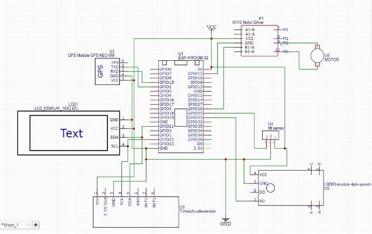
Fig1.2. Circuit Diagram
TheESP32isatthecenterofthesystemandisconnected to various sensor that perform different functions. The first is the LCD display, which shows the sensor values in real- time. Thedisplay is connected to theESP32 through the I2C interface. The second is the GPS module that retrieves the location of the vehicle. The GPS moduleis connected to the ESP32 through the serial interface. The third sensor includes the accelerometer sensor, tilt vibration sensor, and speed sensor.These sensors detect any sudden changes in speed, direction, or tilting of the vehicle. Theaccelerometersensorandtiltvibrationsensor are connected to the ESP32 through the ADC interface, whilethespeedsensorisconnectedtotheESP32through the GPIO interface. The fourth includes the motor driver that controls the motor. The motor driver is connectedto theESP32throughthePWMinterface.TheESP32sendsa
International Research Journal of Engineering and Technology (IRJET) e-ISSN: 2395-0056
Volume: 11 Issue: 04 | Apr 2024 www.irjet.net p-ISSN: 2395-0072
signal to the motor driver, which controls the motor speed. Finally, all the sensor data is sent to the Firebase server. The ESP32 is connected to the Firebase server through the Wi-Fi interface. The ESP32 sends the sensor data to the Firebase server using the Firebase API. In summary, the IoT based accident detection system connected to an ESP32 includes an LCD display, GPS module,accelerometersensor, tilt vibration sensor,speed sensor, motor driver, and Firebase server. The ESP32 retrievesdatafromeachblockandsendsittotheFirebase server,whereitcanbeviewedinreal-time.
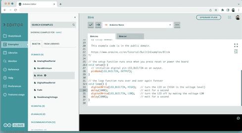
1.3.1
Another integral part of the Arduino ecosystem are its software tools. The Arduino Integrated Development Environment(IDE)servesasacomprehensiveplatformfor programming Arduino boards. Essentially, it's a software tool that streamlines the entire process of developing and uploading code to your Arduino microcontroller. Before the IDE, programming microcontrollers required significant expertise in both electronics and computer science. However, with the Arduino IDE, this process has become much more accessible to beginners and enthusiastsalike.Fromwritingthecodetocompilingitinto machine language and finally uploading it onto the board, the IDE handles every step seamlessly. This user-friendly interface has democratized microcontroller programming, making it accessible to a wider audience. Today, there are multiple versions of the Arduino IDE available,catering to differentuserpreferencesandneeds.
•ArduinoIDE1.8.x(classic)
•ArduinoIDE2(new)
•ArduinoWebEditor(online)
2. Methodology
1. Requirement Analysis:Conductathoroughanalysis to understand the specific safetyneedsand preferences of the target users. This involves gathering insights through surveys,interviews,andconsultationswithpotentialusers andstakeholders.
2. Technological Selection: Identify and select the appropriate hardware components and technologies to fulfillthesystemrequirements.ThisincludeschoosingGPS modulesforlocationtracking,Wi-Fi___33modules(suchas ESP32) for connectivity, panic buttons for emergency triggers, and a robust backend system like Firebase Cloud fordatastorageandsynchronization.
3. System Architecture Design: Develop a comprehensive system architecture that outlines the integration of chosen components. Define the communicationprotocols,dataflow,anduserinterfacesto ensure a seamlessand effective operation of the Women's SecuritySystem.
4. Hardware Integration: - Implement the selected hardware components into a cohesive system. This involves connecting and configuring GPS modules, WiFi___33 modules, SOS switches, and any wearable devices tocreateafunctionalprototype.
5. Mobile Application Development: - Design and develop a user-friendly mobile application that serves as theinterfacefortheWomen'sSecurity System.Ensurethe application allows users to monitor the live location, receive emergency alerts, and trigger assistance seamlessly.
6. Real-Time Communication Mechanisms:Establish communication mechanisms between the hardware components and the mobile application to facilitate real-time data transfer. This includes setting up communication protocols for GPS data, emergency alerts, andsystemstatusupdates.
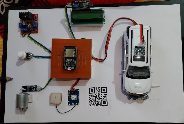
3. RESULTS AND DISCSSION
International Research Journal of Engineering and Technology (IRJET) e-ISSN: 2395-0056
Volume: 11 Issue: 04 | Apr 2024 www.irjet.net p-ISSN: 2395-0072
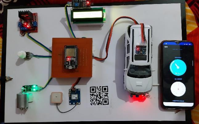
4. APPLICATIONS • Real-time accident detection • Emergencyresponse:• post-accident analysis:•Insurance claims•Vehicletracking
5. CONCLUSIONS
The IoT-based vehicle accident detection and tracking systemusingGPSModempresentedinthisprojectoffersa promising solution to address the rising number of casualties associated with road collisions. By leveraging IoT technology, our system not only detects accidents but also alerts authorities promptly, facilitating timely rescue operations and potentially saving lives. We discussed various strategies for accident detection and prevention, includingtheuseofsensorssuchasaccelerometers,shock sensors, and pressure sensors, coupled with machine learning techniques such as neural networks and support vector machines. These strategies aim to enhance the accuracy and efficiency of accident detection, as well as prevent accidents through measures such as detecting drunk or drowsy drivers and regulating vehicle speed. Once an accident is detected, the system communicates the information to emergency services, enabling them to provideswiftassistance.Overall,thissystemoffersseveral advantages, including mitigating road collisions, pinpointing precise accident locations, and streamlining rescueoperations.
6.REFERENCES
[1]AishwaryaS.R,AshishRai,Charitha,PrasanthM.A,and Savitha S.C“AnIoT basedvehicleaccident prevention and tracking system for night drivers” proc. IEEE, vol.3,no.4,pp.2320-97982015
[2] Sadhana B Shabrin, Bhagyashree Jagadish Nikharge, Maithri M Poojary and T Pooja, “Smart helmetintelligent safety for motorcyclist using raspberry pi and open CV”, proc.IEEE,vol.03, no.03 pp.2395-0056 2016
[3] Jagdish A. Patel, Aringale Shubhangi, Shweta Joshi, Aarti Pawar and Namrata Bari discussed on
“Raspberry Pi based smart home”, Proc. IEEE, vol.6, no.3,pp.2321-33612016
[4] Dr. pankaj Tomar and preeti Mehta focused on “ An Efficient Management System based on Face Recognition using Matlab and Raspberry Pi 2”, ProcIEEE,vol.3,no.5,pp.2392016
[5] T. Anitha and T. Uppalaigh focused on “Android based home automation using Raspberry pi”, Proc-IEEE, vol.04,no.01,pp-2351-86652016
[6] Shailesh Bhavthankar and Prof. H.G.Sayyed discussed on” Wireless System for Vehicle Accident Detection and Reporting using Accelerometer and GPS”, Proc .IEEEvol.6,no.8,pp-2229-55182015
[7] Md.Shaad Mahmud, Honggang Wang, A.M.Esfar-EAlam and Hua Fang has focused on “A Wireless Health Monitoring System Using Mobile Phone Accessories”, ProcIEEE,vol.1,no.99,pp-2327-46622016
[8] Sarika R. Gujar and Prof. A. R. Itkikar has focused on “Advanced Embedded System of Vehicle Accident Detection and Tracking System”, Proc-IEEE, vol.5, no.2,pp-2277128X2015