
International Research Journal of Engineering and Technology (IRJET) e-ISSN: 2395-0056
Volume: 11 Issue: 04 | Apr 2024 www.irjet.net
p-ISSN: 2395-0072


International Research Journal of Engineering and Technology (IRJET) e-ISSN: 2395-0056
Volume: 11 Issue: 04 | Apr 2024 www.irjet.net
p-ISSN: 2395-0072
Ayush Pandey1, Vikash Dwivedi2
1M.Tech (ME) Scholar, Department of Mechanical Engineering, B. N. College of Engineering & Technology Lucknow, Uttar Pradesh, India
2 Assistant Professor, Department of Mechanical Engineering, B. N. College of Engineering & Technology Lucknow, Uttar Pradesh, India
Abstract - Internal combustion (IC) diesel engines are establishedasthemainpowersourcefortheautomobiles and marine vessels due to its superior efficiency over the other engines. The efficiency and life of IC diesel engines are one of the important criteria. An extensive work has been carried out to increase the efficiency of the engine, but only few works has been done in the area of service lifeofdieselengine.Therearevariousmethodstoincrease thelifeofengine,like VariableCompressionRatio(V.C.R), different materials of construction, fuel type and fuel quality. Hence, in the present work, an experimental analysis is carried out on Variable Compression Ratio (V.C.R.) diesel engine to measure the engine performance and to determine its optimal compression ratio at a constant speed of 1500rpm. The operational parameters like efficiencies and power adopted are determined at different compression ratios of 16.5, 17.0, 17.5, 18.0 and 18.5 at different loads. Kinematic and Dynamic stress analysis is performed on Piston, Connecting rod and Crankshaft to identify the thermal and structural stresses induced in the VCR engine followed by fatigue analysis to determineitslifeandfactorofsafety.
The experiment is validated through the simulation. The simulationconsistsofthermal,structuralandthethermomechanical analysis. The thermal analysis provides the effect of temperature on the crankshaft, while the structural analysis determines the fatigue life of the crankshaft. Kinematic and dynamic analysis helps in providing the forces on the crankshaft, which are responsibletogeneratethestress.Theforcescanbefound out by the use of free body diagrams. These forces will continue to change in its magnitude and direction. Hence crankshaft is subjected to the reversal of stresses. It will reducethelifeoftheengine.
ThedesignoftheV.C.R.wascarried outatpeakpressures and maximum temperatures are obtained through the experimentfordifferentC.R.atdifferentcrankangles.For design,optimizationandanalysis,Solidworks,andANSYS software were used. Different materials were considered for the different components for the optimization and increaseoflifeoftheengine likeAISIE4340Forgedsteel, Aluminumalloy7075-T6etc.Totaldeformationandfactor ofsafetyatdifferentcrankanglesforthetwomaterialsare
analyzed. The fatigue analysis is carried out to know the factorofsafetyofthetwomaterials.
The stress analysis was carried at critical angles of 3650 , 4900,5400 and5900 withdifferentloadingconditionsata constant compression ratio of 16.5. The results obtained from the structural analysis shows that the stresses induced at the crank pin and bearing supports in the aluminum alloy (7075-T6) are lesser in comparison with AISIE4330forgedsteel fordifferentcrank angles.Forthe above crank angles, structural analysis was done using ANSYS and the results show that the stresses and total deformation are more at crank pin than at bearing supports. The analytical and ANSYS results were compared for both the materials. It was found that the variationinthestressvaluefortheAluminiumalloyisless than 1% and for the forged steel is less than 5%. The simulation performed is in very good agreement with the analytical results.
The fatigue analysis is conducted for 106 cycles at all critical angles for two materials of the crankshaft. The results shows that the minimum factor of safety these materialsisfoundtobe4.24forAluminiumalloyand3.80 forForgedsteel.Themaximumfactorofsafetyisfoundto be15.10 for Aluminium alloy and forged steel. The working life of the Al-alloy (17777 hrs.) is more than the forged steel (10233 hrs.), which can lead to lowering the overall cost of the engine. The comparative result shows thatthealuminumalloy(7075-T6)exhibitsbetterlifethan forgedsteelat16.5optimumcompressionratio.HenceAlalloy is the best choice for the material construction for thecrankshaft.
Key Words: Variable Compression Ratio (V.C.R.), Solid works, and ANSYS software, Aluminium alloy, fatigue analysis.
Crankshaftisalargecomponentwithacomplexgeometry in the engine. The crankshaft, connecting rod, and piston constitutes a four-bar slider-crank mechanism, which convertsthe reciprocatingdisplacementofthepistonto a rotary motion with a four-link mechanism. Since the

International Research Journal of Engineering and Technology (IRJET) e-ISSN: 2395-0056
Volume: 11 Issue: 04 | Apr 2024 www.irjet.net p-ISSN: 2395-0072
rotation output is more practical and applicable for input tootherdevices,theconceptdesignofanengineisthatthe output would be a rotation. In addition, the linear displacement of an engine is not smooth, as the displacement is caused by the combustion of fuel in the combustion chamber. Therefore, the displacement has suddenshocksandusingthisinputforanotherdevicemay cause damage to it. The concept of using crankshaft is to change these sudden displacements to a smooth rotatory output, which is the main input to many other devices suchasgenerators,pumps,andcompressors.
During the service life of a crankshaft, it is subjected to several cyclic bending and torsion loads induced by the pressure generated from the combustion process and the inertia of the components in relative motion. The magnitude of the force depends on many factors which consist of crank radius, connecting rod dimensions, the weightoftheconnectingrod,piston,pistonrings,andpin. Combustion and inertia forces acting on the crankshaft cause two types of loading on the crankshaft structure: torsionalloadandbendingload.
Mechanical failures of the crankshafts are caused by fatigue phenomena. For improvement of the fatigue resistance, they are mainly ascribed to both the residual stress field and the surface hardening. Surface treatments of mechanical components are usually applied for increasing the hardness and wear resistance without the modification of the mechanical characteristics of the bulk material, but recently it is demonstrated that they also increasethe fatigue limit becauseofcompressive residual stressinducedatthesurfaceandsubsurfacelayers.
In the present work, an experiment is carried out on VariableCompressionRatio(V.C.R.)enginetomeasurethe engine performance of an internal combustion (IC) Diesel engine and to determine its optimal compression ratio. Kinematic and Dynamic stress analysis is performed on Piston, Connecting rod and Crankshaft with various materials to identify the thermal and structural stresses induced in the IC engine followed by fatigue analysis to determineitslifeandfactorofsafety.
During the last decades, researchers and manufacturers invented several engine concepts that with variable compression ratio. Shaik et al. (2007), Nilsson (2007), Gupta (2012), Radonjic (2010), and Wos et al. (2012), proposeddifferentclassificationsoftheVCRfield.Thus,in order to understand their classification and tocheck their completeness,itwasdecidedtorunapatentsurvey.More than 1000 patents from 1974 to 2014 were analyzed the trendfortheVCRresearch.Since2000,thenumberoffiled patents has been increasing significantly, suggesting a growing interest from automotive sector. From 2013 to the present date, the numbers are still incomplete since
some patent applications are under confidential status. Excluding from the survey all patents related to control, hydraulics andimprovements ofprevious designs, a total of 127 different VCR engine designs (patent families) remained.
Crankshaft is an important component of internal combustion engine with complex geometry. Crankshaft experiencesalargenumberofloadcycleduringitsservice life (Taylor and Ciepalowicz 1997). The sudden failure of crankshaft made researchers and academia to investigate the problem. Because of complicated loading and geometry problem, general method to predict fatigue life is still not evolved.Since crankshaft is subjected to several forces which vary in magnitude and direction (multiaxial)andconnecting rodtransmitting gaspressure fromcylindertocrankpin,stressesactinginthecrankshaft vary with respect to time (Montazersadgh and Fatemi, 2007) Most of the time crankshaft fails due to fatigue at fillet areas due to bending load. Fillet rolling can increase fatiguelife[Parket.al.2001].
The work on the service life of IC engine with respect to thefailureofdifferent components was nottouched upon ingreatdetails.TheICenginehasdifferentcomponentsas Cylinder head, Cylinder, Piston, Connecting Rod, Crankshaft etc. To increase the overall service life and performance of the engine, each component has to be analysed in detail. A Comprehensive examination of existing literature relatedsome of the research gaps in the work reported on crank shaft of different compression ratios at different crank angles. The observations lead to formulation of the present research investigationasfollows.
1. Mostofthecrankshaftsthatfailedinfatiguewere due to bending fatigue. The workon the service life of IC engine with respect to the failure of different components was not touched upon in greatdetails.
2. From literature survey it is understood by this authorthatthereisalotofscopefor studyingthe stress analysis with different compression ratios andatdifferentcrankangles.
3. Taking into these considerations, the author has embarkedonstudyingthestressanalysisofcrank shaft with three compression ratios and at four crankangles.
Experimental tests were conducted on a Variable Compression Ratio (VCR) diesel engine at Engines Laboratory in the Department of Mechanical Engineering, Anil Neerukonda Institute of Technology and Science (ANITS)Autonomous,VisakhapatnamIndia.

International Research Journal of Engineering and Technology (IRJET) e-ISSN: 2395-0056
Volume: 11 Issue: 04 | Apr 2024 www.irjet.net
VCR engine test rigcan beusedtodetermine the effect of compression Ratio (CR) on the performance and emissions of the engine. It can also be used tostudy the health i.e. life of the engine. However, the objective is to determine the optimum compression ratio for which the best performance with good life is possible. The test rig has one very important feature that the compression ratiocanbevariedin thestepsof0.5.Hencetheoptimum compression ratio can also be found out between the two CRintegerslike16.0,16.5,17.0,17.5,18.0,18.5etc.
3.1. Experimental process
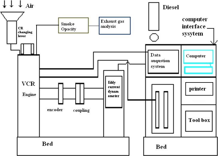
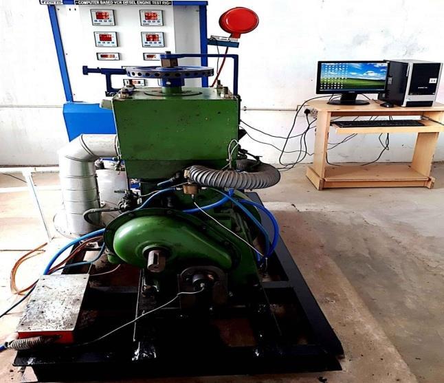
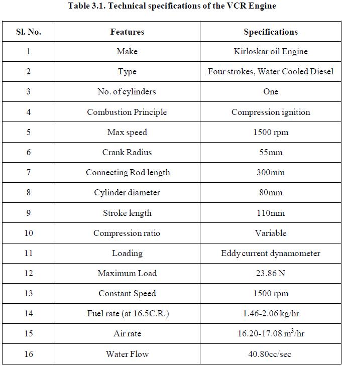
Experimentations were carried out on a single cylinder watercooled fourstrokevariablecompressionratio(VCR) dieselengine.Figure3.1representstheschematicdiagram with different components present in it. The engine is tested at different compression ratios varying from 16 to 18.5withanincrementof0.5by maintainingfixedrpmof 1500. Eddy current dynamometer is used for loading purpose, parameters like cylinder peak pressures, brake thermal efficiency and brake specific fuel consumption weremeasured.
The performance results of 16.5, 17.5 and 18.5 compression ratio were chosen for the kinematic and dynamic analysis of piston and crank mechanism. The detail description of equipment’s and their specifications werediscussedinthefollowingsections.
4.1. Thermal Analysis results for crankshaft at 365degrees crank angle
Steady state thermal analysis is considered before the structural analysis, in this analysis, boundary conditions (heat transfer coefficient, heat flux) are applied on the piston and we observe the maximum and minimum temperatures, and the totalheatfluxofpiston.Asteadystate thermal analysis may be either linear with constant materialproperties,ornonlinearwith materialproperties that depend on temperature. The thermal properties of

International Research Journal of Engineering and Technology (IRJET) e-ISSN: 2395-0056
Volume: 11 Issue: 04 | Apr 2024 www.irjet.net p-ISSN: 2395-0072
the most material do vary with temperature, so the analysisusuallyisnonlinear.7075-T6materialsatcritical angles of 365, 490, 540 and 590 by considering the (Rax, Ray)&(Rox,Roy)forcesappliedatcrankpinandbearings supports The structural results of Equivalent stresses and deformations obtained from ANSYS are shown in Table4.1.
At different critical angles between 0 to 720 degrees with variation of force components over one complete engine cycleatthecrankshaftspeed1500rpm
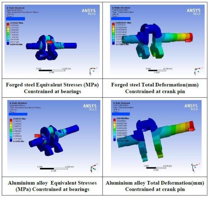
Figure 4.1 Crankangle365degreesMaximumvaluesof Equivalentvon-MisesstressesandTotalDeformation
Table 4.1 MaximumvaluesofEquivalentvon-Mises stressesandTotalDeformation
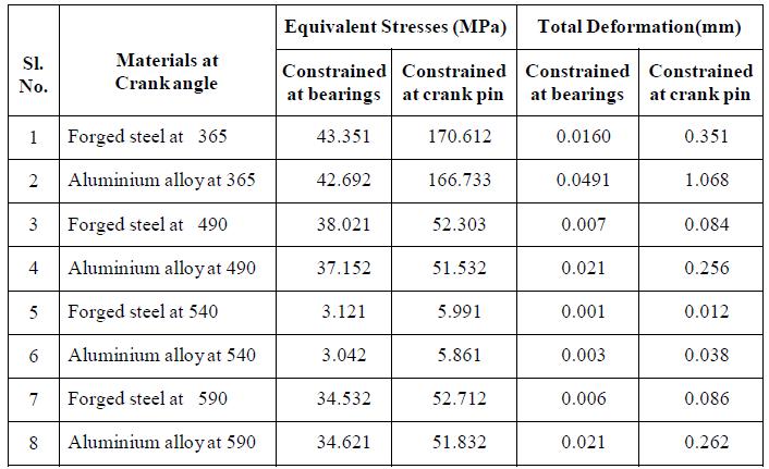
Fromthetable4.1,itcan be observed that stresses and total deformationare more at crank pin than at bearing supports. Minimum stresses are obtained at crank angle 5400 and maximum stresses are obtained at crank angle 3650, as shown in figure 4.1. The order of stresses is
same for both the materials at all critical angles of rotation but the deformation is almost three times higher in Aluminium alloy when compared to forged steel.
Validation of Results (Al-Alloy) Stress validation at Crank PinLocationSectionmodulusofCrankPin=16333mm3 Distanceofforceforthebendingmoment=18.5mm
4.2. Thermo-Structural Analysis of Crankshaft
Thermo-Structural Analysis for different crank angles of the crankshaft is shown in the figure below. The body temperatureisbeenimportedfromtheresultsofthestatic thermalanalysisasshowninthefigure4.2.
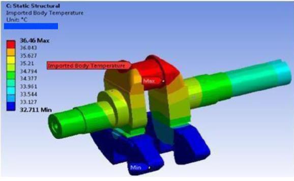
Figure 4.2 ImportedBodyTemperaturefromthermal analysis
After importing the thermal load, the static structural analysis is carried out forwhich the equivalent stress and totaldeformationareshownbelowinfigure4.3a&b.
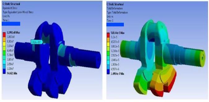
Figure 4.3 (a)and(b)EquivalentStressandTotal Deformationonthecrankshaft
Thermo-Structural(365)degreescrankangle.
Von-Mises Stress at Crank Pin Location (Structural) = 28.26Mpa
Von-Mises Stress at Crank Pin Location (ThermoStructural)=30.37Mpa
IncreaseinStresses=2.11Mpa

International Research Journal of Engineering and Technology (IRJET) e-ISSN: 2395-0056
Volume: 11 Issue: 04 | Apr 2024 www.irjet.net p-ISSN: 2395-0072
Hence the effect of temperature can be neglected for all othercases.
4.3. Fatigue Analysis on Al-Alloy and Forged Steel crankshaft
During the service life of a crankshaft, they are subjected toseveralcyclicbendingandtorsionloadsinducedbythe pressure generated from the combustion process and the inertia of the components in relative motion. The magnitude of the force depends on many factors which consist of crank radius, connecting rod dimensions, the weightoftheconnectingrod,piston,pistonrings,and pin Combustion and inertia forces acting on the crankshaft causes two types of loadings on the crankshaft structure, torsionalload,andbendingload.Mechanicalfailuresofthe crankshafts are caused by fatigue phenomena. For improvement of the fatigue resistance, they are mainly ascribed to both the residual stress field and the surface hardening. Design developments have always been an important issue in the crankshaft production industry. In ordertomanufacturealessexpensivecomponentwiththe minimum weight possible by proper fatigue strength and other functional requirements, these improvements result in lighter and smaller engines with betterfuel efficiencyandhigherpoweroutput.
Fatigue analysis is carried out for Al-Alloy and Forged Steel with the rotational velocityof crankshaft 158 rad/s showninfigure4.4.
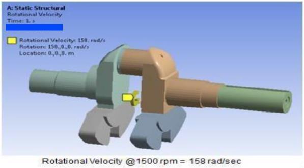
4.4 CrankShaftBoundaryConditionsforFatigue analysis.
Table 4.2 FactorofSafetyvaluesatdifferentcrankangles

Hence in the present work, fatigue analysis is carried out at all critical angles for both the materials and the results
of Factor of safety are shown in table 4.2. In this analysis consists of determining the factor of safety for a minimum assumed number of cycles of 106. As the maximum factor of safety istobeconsidered,a factor of safety of 15.1 has to be taken for both the materials are shown Appendix D and E .The aluminum alloy is a moresuitablematerialwithrespecttotheforgedsteel.The working life of the Al-alloy (17777 hrs.) is more than the forged steel (10233 hrs.).The temperature of the combustion chamber is having the less effect on the crankshaft.
The structural, thermal and fatigue analysis results are discussed. The maximum temperature achieved in the cylinder head does not affect the temperature profile of crankshaft. The thermo-structural analysis concludes that boththematerialsofthecrankshaftaresuitable.
But the working life of Al-Alloy is more than forged steel. Hence Al-alloy is the best choice for the material constructionfor thecrankshaft.
Following conclusions were derived during the experimentalstudy:
Maximumpressureandtemperatureswerefound at the different compression ratios during the combustion of the gases inside the IC engine cylinder . It is observed from the experimental data that there is an increase of brake thermal efficiency with CR. The maximum temperature occurs on the piston crown and minimum temperature at piston skirt for all compression ratios.
Thermal analysis was performed to get the heat transfer from the connected components to the crankshaft.Theconnectedcomponentswhichcan affect the crankshaft are cylinder head, cylinder, piston and connecting rod. The stresses developed from the temperature gradient is not significantduetotheheatremovalatthedifferent stages.
The results obtained from the structural analysis shows that the stresses induced at the crank pin and bearing supports in the aluminum alloy(7075-T6)arelesserincomparisonwithAISI E4340forgedsteelfordifferentcrankangles.
For the above crank angles, structural analysis was done using ANSYS and the results show that the stresses and total deformation are more at crank pin than bearing supports. Minimum stressesareobtainedatacrankangleof5400 and

International Research Journal of Engineering and Technology (IRJET) e-ISSN: 2395-0056
Volume: 11 Issue: 04 | Apr 2024 www.irjet.net p-ISSN: 2395-0072
maximum stresses are obtained at a crank angle of3650 .
The order of stresses are same for both the materials at all critical angles of rotation, but the deformation is almost three times higher in Aluminium alloy when compared to the forged steel. Thus, Aluminium alloy(7075-T6) exhibits better results in comparison with AISI E4340 Forgedsteel.
The analytical and ANSYS results were compared for both the materials. It was found that the variation in the stress value for the Aluminium alloyislessthan1%andfortheforgedsteel,it is less than 5%. Hence it is verified that simulation performed is in very good agreement with the analyticalresults.
The thermo-structural analysis concludes that both the materials of the crankshaft are suitable. But the working life of Al-Alloy is more than forged steel. The working life of the Al-alloy (17777 hrs.)and the forged steel (10233 hrs.), whichcanlead tolowering theoverall costofthe engine.
The fatigue analysis of two different materials is conductedfor106 cycles.Thisanalysiscarriedout atallcriticalanglesforboththematerialsandthe resultsshowsthattheminimumfactorofsafetyis foundtobe4.24forAluminiumalloyand3.80for Forged steel. The maximum factor of safety is foundtobe15.1forboththematerials.
The results conclude that Aluminum alloy (7075T6) exhibits better results in comparison with AISIE4340 forged steel for the crankshaft. Hence Al-alloy is the best choice for the material constructionfortheCrankshaft.
There is lot of scope for production of crankshafts as per ASTM standards with new materials and manufacturing themasperthespecifications,foroperationofICengines. Further analysis can be performed on the crankshaft in order to optimize the manufacturing cost. Further research can be implemented for different speeds of the engine. Simulation of IC engine with Computational Fluid Dynamic (CFD) analysis on VCR engine with Diesel and alternative fuels to enhance the overall performance and lifeoftheenginecanbecarriedout.
[1] Abe, K., and Yoshimatsu, A., 2011, Intake Port Structure of Internal Combustion Engine,‖ U.S. PatentNo.US7938099B2.
[2] AbhishekPaul,SubrataBhowmik,2018 "Artificial Neural Network-Based Prediction of Performances Exhaust Emissions of Diesohol Piloted Dual Fuel Diesel Engine Under Varying Compressed Natural Gas Flowrates" Journal of EnergyResourcesTechnology Vol.140/1122011.
[3] Alain, R., Violan, P., and Mendez, J., 1997, Low Cycle FatigueBehavior in Vacuumofa316LType AusteniticStainlessSteelBetween20and600°CPart I: Fatigue Resistance and Cyclic Behavior,‖ Mater.Sci.Eng.,A,A229,pp.87–94.
[4] Angel, T., 1954, Formation of Martensite in Austenitic Stainless Steel,‖ JIron Steel Inst., London, 177,pp.165–174.
[5] ANSYS, 2009, CFX-Mesh,‖ ANSYS, Inc., Canonsburg, PA Saad, I., and Bari, S., 2013, Improving Air-Fuel Mixing in Diesel Engine Fuelled by Higher Viscous Fuel UsingGuide Vane Swirl and Tumble Device (GVSTD),‖ SAE Paper No.2013-01-0867.
[6] ANSYS, 2009, Internal Combustion Engine,‖ ANSYS, Inc., Canonsburg, PA Hino, 2008, Diesel Engines for Industrial-Use,‖ Hino Motors Ltd., Tokyo,Japan.
[7] ASTM Standards E606-04, 2007, Standard Practice for Strain-Controlled Fa- tigueTesting,‖ Annual Book of ASTM Standards, Vol. 03.01, American Society for Testing and Materials, WestConshohocken,PA,pp.656–671.
[8] ASTM Standards E606-04, 2007, Standard Test Methods for Tension Testing of Metallic Materials Metric ,‖ Annual Book of ASTM Standards,Vol.03.01,AmericanSocietyforTesting and Materials, West Conshohocken, PA, pp.89–113.
[9] Australia Renewable Fuel Limited (ARfuels), 2013, Material Safety Data Sheets (MSDS) and Specifications,‖ Australia Renewable Fuel Limited,Melbourne,Australia.