
Volume: 11 Issue: 04 | Apr 2024 www.irjet.net p-ISSN: 2395-0072
Volume: 11 Issue: 04 | Apr 2024 www.irjet.net p-ISSN: 2395-0072
Dr. Ajit Kumar Patro1 , Aryan Kumar2 , Moudipa Mondal2 , Nikhil Kumar2 , Sweta Rani2
1Associate Professor, dept. of Electronics and Communication Engineering, GIET University, Odisha, India 2UG Scholar, ECE department, GIETU, Gunupur ,Odisha , India
Abstract – Development of a Cellular Signal Identifier enhances security and privacy. The ubiquity of cellular device has raised Cellular Device Monitoring concerns regarding their misuses in many sensitive areas, such as secure facilities, examination centers and theaters, where their usage poses security threats and invades personal privacy. To address this issue, we have developed a Cellular Signal Identifier, a compact and efficient device capable of detecting and alerting to the presence of active cellular devices within its vicinity. This paper outlines the design, construction, and testing of the Cellular Signal Identifier, emphasizing its functionality, sensitivity, and real-world applications. We also explained the implementation of a user-friendly interface that allows us for an easy configuration and monitoring. The results indicate high sensitivity and minimal false alarms, furthermore we also discuss the ethical and legal considerations associated with its use, as well as its potential impact on societal norms.
Key Words: Signal, sensitive, identifier, cellular, userfriendly,privacy,design,construction.
Acellulardevice,oftenreferredtoasamobiledeviceorcell phone,isa portableelectronicgadgetthatutilizescellular networksforcommunication.Thesedevicesenableusersto receivephonecalls,sendmessages,andaccesstheinternet wirelessly [1]. Concerns about using mobile phones in unapproved,restrictedregionshavereceivedmoreattention inrecentyears.Theinappropriateuseofmobilephonesby bothownersandusersisamajorcontributingfactortothe risinginterest[2]Notexcludedareotherspaceslikeoffices, churches, and mosques, to name a few. In places such as these,mobilephonesignaldetectionisnecessary.
Manyideasandinnovationsaredonetosolvethisproblem but all of these solutions have its own limitations and shortcoming.
One of those innovations is signal jammer, it is used to preventcellulardevicesfromreceivingRFsignals[3].When thisjammeruseditdisablesthephonesforthetimingit’s activebecauseofjammingthesignals.Jammerismainlyis usedinsuchplaceswheresilenceisprimarythingorinsuch places where use of cell phones is prohibited [4]. The limitationofthisjammeristhatapersoncannotusehis/her cellulardeviceinthecaseofemergencies.
Thecellularsignalidentifierallowstheuseofcellphonesin emergenciesbecauseitjustdetectstheRFsignals,itdoesnot blockthem,exceptthealarmwillkeepbeepingandthelight willbecontinuouslyblinking.
The cellular device produces RF signals which has wavelength 30Cm at 872 up to 2170 MHz, this signal has hugeenergyfrequencyandhighfrequency.[5]
In2019,Y.Gao,etal.intheirpaper"MobilePhonePassive PositioningThroughtheDetectionofUplinkSignal,"states thattheprocessofhigh-precisionlocatingand,apassiveway for locating the cellular device by capturing the preamble sequencewhichcanbeappliedto5Geven4Gcommunication system[6].In2010,Berkeleyetal.VaritronicsSystems,“Cell phone Detector” these Companies produce the wolfhound cellular device detector and cellular buster. The Berkeley VaritronicssystemsWolfhoundcellphonedetectsComputers (PCs), Global System for Mobiles (GSM) andCode Division Multiple Access (CDMA), cell phone bands using RF InternationalJournalofEngineeringResearch&Technology (IJERT) [7]. In 2014, Ajasa, A.A. et al. “Design and Development of a Mobile Phone Signal Detector”, has proposed in their paper that the presence of an activated cellular device can be detected by this device, which is pocket-sizedcellularsignaldetectorwhichcandetectfroma distance of one or a half meter, which can be used in preventingtheusagesofcellulardeviceinconfidentialrooms, examinationhalls,[8].In2011,Scott,Nicholas,etal.“Studyof CellularPhoneDetectionTechniques”.Thispaperstudiesthe techniquesofdetectingcellulardevices.Itexaminesaboutthe technologieswhichiscurrentlyavailable,analreadyexisting designwhichutilizesmaximumdiscretecomponents,anda design by using a down converter; in conjunction with a bandpassfilter[9].In2015,DeshpandeTamvietal."Active Cell phone detection and Display using Atmega-8 Microcontroller”,thepaperdealswiththedetectionofGSM signalsanddisplayingthesignalsonaLCDscreenwiththe use of an ATmega-8 microcontroller. According to it the cellulardevicewillamelioratetomaintaintheformationof securityintherestrictedareastoprotectthebreachpotent data[10].
International Research Journal of Engineering and Technology (IRJET) e-ISSN: 2395-0056
Volume: 11 Issue: 04 | Apr 2024 www.irjet.net
Duetothetransmissionandhighfrequencyandenormous energy outcome, signals from the GHz frequency bandare usedincellulardevicewhichcannotbedetectedbyaregular RFdetectorthatusestunedLCcircuits.
Thistinymobilephonesignaldetectorhasanextremelyeasyto-assemble, low-cost construction. The more thorough descriptionofthedesignofusethegivenblock diagramis necessary in order to make the construction more comprehendedandappreciated.
Thedesignofcellularsignalidentifierhasfourstages.
1. Inputstage
2. Amplificationstage
3. CommonEmitterAmplifierstage
4. NE555timerstage
2.1. Materials Used
Table -1: Componentsusedinthecircuit
2.1.1. IC CA3130
TheCA3130isaversatileoperationalamplifierknownforits high input impedance, low input current, and excellent frequencyresponse.Withitswidesupplyvoltagerange,it's adept at various signal processing tasks, including audio amplification,filtering,andinstrumentationapplications.
2.1.1. IC NE555
TheNE555ICisaversatileandwidelyusedintegratedcircuit knownforitstimerandoscillatorfunctionalities.Thischipis favoredforitsabilitytogenerateaccuratetimedelaysand oscillatingsignals.
p-ISSN: 2395-0072
The buzzer is an electro-acoustic system which produces sound by generating vibrations through an oscillating electroniccircuit.Ittypicallyconsistsofanelectromechanical componentthatproducesanaudibletoneornoise.
Theresistorisanelectricalcomponentwhichisdesignedto limittheflowofelectriccurrentinagivencircuit.Theyare usedtoreducethevoltagelevels,italsocontrolstheamount ofcurrentflowthroughacircuit,dividethevoltages,adjust the signal levels, and also limit the current to LED lights, amongmanyotherapplications.
A capacitor is an electrical component used to store and releaseelectricalenergyinacircuit.Whenvoltageisapplied across the plates, it stores electric charge. Capacitors are characterizedbytheircapacitance,measuredinfarads(F), whichdeterminestheirabilitytostorecharge
2.1.6.
TheLEDisashortformofLightEmittingDiode,whichisa semiconductordevicewhichemitslightwheneveranelectric currentispassingthroughit.
2.1.7.
BC548 is a commonly used NPN (BJT) bipolar junction transistor which is employed in a wide array of electronic circuits.Knownforitsversatility,thistransistorissuitablefor low-power applications, serving as an amplifier for small signals or as a switch to control higher currents based on inputsignals.Withitsthreeterminals-Base,Collector,and Emitter.
The battery is an energy storage device that converts the chemicalenergyintoelectricalenergy.Batteryconsistsofone or electrochemical cells, which contains of positive and negativeterminals(anodeandcathode)anditisimmersed intoanelectrolytesolution.Whenitisconnectedtoacircuit, the chemical reactions within the it produces electrical current.
International Research Journal of Engineering and Technology (IRJET) e-ISSN: 2395-0056
Volume: 11 Issue: 04 | Apr 2024 www.irjet.net p-ISSN: 2395-0072
2.2. Block Diagram


2.3. SIMULATION
AwireisattachedtoaLED'slongterminal(pin8)whichisat thebottomoftherightrow.(Pin2)ICisconnectedtooneof the ends of a long wire, or an antenna. Then the battery's blackwireisattachedtotheboard'sbottomleftcorner,and theredwireisattachedtothebottomrightcorner.
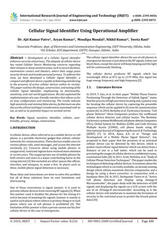
Designing an affective Cellular Signal Identifier circuit requires a good understanding of electronics and wireless communication. Here, is the fundamental design of the circuit:
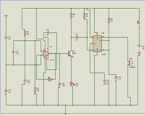
2.3.1. Input stage
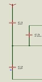
Fig -3:InputStage
Thisabovecircuitreceivesradiofrequency600MHz–39GHz signalsusinga gigahertzloop antenna and toacquire high radio frequency. Because of its wide surface area and inexpensive value, the 22 pf(C2) is the material ofchoice. Signals from the electronics device are intercepted by C2, which then transmits energy in the form of current to the integratedcircuitinputamplificationstageCA3130.
2.3.2.CA3130 Amplification Stage
Fig -4:CA3130AmplificationStage
Large resistor R1 and capacitor C4 maintain noninverting input steady, allowing for a simple output swing to high. CapacitorC4hasadischargerouteprovidedbyresistorR4. Whentheoutputrises,thefeedback resistor,R3,turnsthe invertinginputhigh.Phaseadjustmentandgaincontrolare employedviacapacitorC5,whichislinkedacrossthestrobe pin,tomaximizethefrequencyresponsiveness.
International Research Journal of Engineering and Technology (IRJET) e-ISSN: 2395-0056
Volume: 11 Issue: 04 | Apr 2024 www.irjet.net p-ISSN: 2395-0072
2.3.3. Common Emitter Amplifier Stage
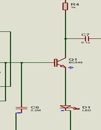
Fig -5:CommonEmitterAmplifierStage
TransistorQ1actsasaswitchtodeliveraDCvoltageforthe second stage. R4 connected with the collector side of the transistor helps to maintain the desired voltage of 5.8 V. Transistor Q1's bias is maintained by C4 to enable quick switching.
2.3.1.NE555 Clock Circuit
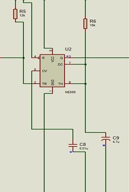
Fig -6:NE555ClockCircuit
The circuit is a basic NE555 timer blink circuit when the timeractsasastableoscillator,up-to-datedforourdesired frequencyinordertodriveourcircuit.
Inthispaperwehaveusedtwocircuitstodetectthepresence of cellular device. After analyzing the outcomes of these circuits, we concluded that whenever a cellular device is broughtnearthecircuitwhichhasantennainit,detectsthe radioactivefrequency(RF)thatareemittedbythecellular devicewhenit’sinuseoritisinstandbymode.Thisantenna Cellular Signal Identifier consists of a high-frequency
transistorandatunedLCcircuit.Thatcouldserveasatiny antennaforgigahertzloops.Diskcapacitorandtheleadofthe LCcircuitcollectstheRFsignalsfromthecellulardeviceand amplifythemusingthetransistor.Theamplifiedsignalsare thenfedtoabuzzeroraLEDthatindicatesthedetectionof themobilephone.
Table 2: Voltagesofdifferentcomponentsduring presence/absenceofsignal
Components
(whenthereis nosignal)
The frequency that is switched by a sequence of two capacitors is detected by the antenna. The 900–1800 GHz frequencyrangeisdetectablebytheantenna.
TheamplifiercanamplifyeventheweakestRFsignalscanbe amplifiedbytheamplifier.Pin6oftheopampproducesa voltageofroughly1voltwhenanactiveGSMisbroughtclose tothecircuit.Thevoltageincreasesordecreasesbetween1.2 and 0.8 volts when the variable ceramic capacitor is connectedbetweenpins1and8.
After the amplification of the signal, it goes to the alarm systemandthebuzzerinthealarmsystemgetactivatedand start producing sound. The sound stays on for the certain timeconstantandthattimeconstantiscontrolledbythe555 timer.ThetimingcomponentsR1andC2influencethedesign ofthemonostabletimer.
Wehaveconcludedaftersimulationsanddesigningcircuit thatwhenevertheRFsignalispassedthroughtheantenna thedeviceisactivatedandthealarmstartproducingsound withaconstanttimeperiodusingNE555timer.Ourdevice playsaverycrucialroleindetectingcellulardevicewhereits useisprohibited.Afterouranalysiswecametoaresultthat the cellular device has to be active in order to detect RF signals produced by the cellular device. The signal is captured, then it goes through an amplification process wherethesignalisamplifiedupto1,00,000timestogetthe betteroutputinthebuzzer.
International Research Journal of Engineering and Technology (IRJET) e-ISSN: 2395-0056
Volume: 11 Issue: 04 | Apr 2024 www.irjet.net p-ISSN: 2395-0072
[1] D. Kornack and P. Rakic, “Cell Proliferation without NeurogenesisinAdultPrimateNeocortex,”Science,vol. 294, Dec. 2001, pp. 2127-2130, doi:10.1126/science.1065467.
[2] M.Young,TheTechnicalWriter’sHandbook.MillValley, CA:UniversityScience,1989.
[3] R. Nicole, “Title of paper with only first word capitalized,”J.NameStand.Abbrev.,inpress.
[4] K. Elissa, “Title of paper if known,” unpublished. [1] Starovoytova, Diana, “Design and Testing of MobilePhone-Detectors”,2016.
[5] [2] H. Du, D. Zhu and D. Sun, "New Solutions for Cell PhoneDetection,"FirstInternationalConferenceonthe Digital Society (ICDS'07), Guadeloupe, French Caribbean,2007.
[6] [3] S. W. Shah et al., "Cell phone jammer," IEEE InternationalMultitopicConference,Karachi,Pakistan, 2008.
[7] [4] E. Divya and R. Aswin, "Design of user specific intelligent cell phone jammer,"1st International Conference on Recent Advances in Informa.tion Technology(RAIT),Dhanbad,India,2012.
[8] [5]M.Vora,S.Krishnadas,Y.PatilandP.Bhavathankar, "Cellular Device Detection in Restricted Premises, "Global Conference for Advancement in Technology (GCAT),Bangalore,India,2019.
[9] [6] Y. Gao, Z. Deng, Y. Zhang, S. Sun and Z. Li, "Mobile Phone Passive Positioning Through The Detection of UplinkSignal,"IEEEInternationalConferenceonSmart InternetofThings(SmartIoT),Tianjin,China,2019.
[10] [7]BerkeleyVaritronicsSystems,WolfhoundCellphone Detector”,AccessedMarch,2010.
[11] [8] Ajasa, A.A., O. Shoewu, and P.O. Nwamina.“Design and Development of a Mobile Phone Signal Detector”, 2014.
[12] [9]Scott,Nicholas.,“StudyofCellularPhoneDetection Techniques”,2011.
[13] [10] Deshpande Tamvi and Jadhav Nakul, "Active Cell phone detection and Display using Atmega-8 Microcontroller,"August2015.