
Design and Development of Continuous Pin Type Mixer for the Fertilizer Industry
Abhishek D. Patil1 , Krishna R. Kupade2 , Suraj A. Hasure3 , Shri M. Koli4, Sheetal P. Udgave5
1,2,3,4 Students of B.tech Mechanical S.I.T.C.O.E., Yadrav (Ichalcaranji), Maharashtra, India
5Assistant Professor of Mechanical Department, S.I.T.C.O.E Yadrav (Ichalcaranji), Maharashtra, India
Abstract - Organic fertilizers are mineral sources that occur naturally and contain moderate amounts of essential the plant nutrients. It can help mitigate problems associated with synthetic fertilizers and reduce the need for repeated application of syntheticfertilizersto maintainthesoil fertility. Organic fertilizers gradually release nutrientsintothe soil solution and a maintain a nutrient balance for the healthy crop growth. Organic fertilizers are generally slow-releasing and contain manytrace elements. They are saferalternativesto chemical fertilizers. However, improper use of organic fertilizers can lead to over-fertilizationornutrientdeficiencyin the soil. Controlled release of organic fertilizers is an advanced and effective way to overcome these impacts and maintain sustainable agriculture yield.
Mixing fertilizer is a complex issue that is not yet fully understood. Many. Even with the same composition, different mixing procedures and mixer types can produce somewhat different microstructures. The fertilizer industry is interested in controlling these influences to produce fertilizerwith wellknown mechanical, rheological, and durability properties. In this overview, we will examine different fertilizer mixers, mixing times, mixing speeds, different addition times of the super plasticizer, and different air pressures inthe mixingpan. We will review existing literature and present some new experimental results.
Key Words: Continues Mixing, Pin Mixer, Homogeneous Mixing, Powder Mixing, Agitation, Bulk Material Handling, MixerDesign,ProcessEfficiency.
1. INTRODUCTION
This document is templateEach Today, we will be discussing a groundbreaking technology that has revolutionizedthefertilizermixingprocess.TheContinuous Pin Type Mixer is a unique machine that offers faster and more efficient mixing solutions compared to traditional mixers.Itsadvancedfeaturesandspecializeddesignmakeita game-changerintheindustry.TheContinuousPinTypeMixer uses a series of pins to blend different types of fertilizer materials.Unlikeconventionalmixersthatrelyongravityor mechanical force, this machineuses high-speed rotation to ensure that every particle is evenly distributed and thoroughly mixed. Exacting standards of the fertilizer industry.
The fertilizer industry and fertilizer research institutes must determine the quality of the fertilizer produced.Toassesshowwella mixerproducesa uniform fertilizer from its constituents, the concept of "mixer efficiency" is often used. According to RILEM, a mixer is efficientifitdistributesalltheconstituentsuniformlyinthe container without favoring one or the other. DIN EN 8-1 proposesthreeclassesofmixers:ordinary,performance,or high-performance.
Eachclassisdefinedbytheobtainedvariabilityof four main parameters (water-to-fine ratio, fine content, coarseaggregatecontent,andaircontent).Severalsamples aretakenfromthemixerandforeachparameter;theaverage and standard deviation are calculated. The coefficient of variation measures the homogeneity of the fertilizer produced. Another way to indicate the efficiency of a mixer is byevaluatingthestructureleftinagranulationafter mixing.
Overall,assessingtheefficiencyofacontinuouspintypemixerisessentialinthefertilizerindustryandresearch. Bymonitoringpropertiessuchassegregationandaggregate grading, and evaluating the structure left in a granulation after mixing, the quality of the fertilizer produced can Be Determined.
1.1 MOTIVATION
Continuouspinmixerspromotematerialhomogeneity byutilizingacombinationofhigh-speedspinningpinsand fluidizingagents.Thismechanismensuresthateachparticle offertilizermaterialisconsistentlycoatedanddistributed throughout the mixture, leading to a homogeneous end product.Thedesignofpinmixerspreventstheformationof clumpsandcakesinthefertilizermixture.Thisiscrucialfor maintainingtheflowabilityandhandlingcharacteristicsof the final product, preventing issues during storage, transportation,andapplication.Fertilizerformulationsoften involveadiverserangeofingredientswithvaryingparticle sizes and properties. Continuous pin mixers are adept at blending these diverse components effectively, accommodatinggranules,powders,andliquidsinthesame process.Incertainfertilizerproductionprocesses,chemical reactionsmaybeinvolved.Thecontinuousmixingactionof pin mixers enhances the contact between reactants, facilitatingefficientanduniformchemicalreactions,leading International Research Journal of Engineering and Technology (IRJET) e-ISSN: 2395-0056 Volume: 11 Issue: 04 | Apr 2024 www.irjet.net
International Research Journal of Engineering and Technology (IRJET) e-ISSN: 2395-0056
Volume: 11 Issue: 04 | Apr 2024 www.irjet.net p-ISSN: 2395-0072
to a more consistent product. Continuous pin mixers can handlevaryingfeedrateswithoutcompromisingthequality of the mixture. This adaptability is crucial in industrial settingswhereproductionvolumesmayfluctuate.Manypin mixers are designed with durability in mind,using robust materialsandconstruction.Additionally,theyoftenrequire minimal maintenance, contributing to reduced downtime and increased overall equipment reliability. Advanced continuous pin mixers often come equipped with instrumentation and controls for precise monitoring and adjustment of mixingparameters. This level of control ensures that the desired specifications for the fertilizer mixtureareconsistentlymet.
2. PROBLEM STATEMENT
Acomputationalinvestigationemploying3Dfiniteelement simulation was conducted to assess the mixing efficiency withinapinmixingsectionofasingle-screwextruder.This study focused on a non-Newtonian, non-isothermal fluid system.Variedaxialgapsbetweenthepinswereconsidered tosimulaterealisticconfigurations.Theevaluationofmixing performance was quantitatively conducted based on the principlesoffluidmixingkinematics.Tolearnandcompare thelocalmixingperformanceinastandardscrewandapin mixing section, the local mixing efficiency distribution proposed by Ottino was calculated. The combination of integrating local mixing efficiency along multiple particle pathlinesfromtheinlettotheoutlet,coupledwithstatistical analysis,referredtoasintegralmixingefficiency,provides The computational findings revealed a non-linear relationshipbetweenthemixingcapabilityofapinmixing section and the axial gap between the pins. These results werethencomparedwithexperimentaldataobtainedfrom priorresearchconductedbyourteam
3. OBJECTIVE
Continuouspin-typemixersinthefertilizerindustryaimto achieve several objectives: Homogeneous Mixing: Ensure uniformdistributionofvariousfertilizercomponents,suchas nitrogen,phosphorus,andpotassium,tocreateaconsistent and balanced blend. Precision Blending: Achieve precise ratios of different fertilizer constituents, crucial for the desirednutrientcompositioninthefinalproduct.Reduced Segregation:Minimizetheriskofparticleseparationduring themixingprocess,ensuringthatthefertilizer'scomponents stayuniformlydistributed.IncreasedEfficiency:Enhancethe overall efficiency of the fertilizer production process by providingacontinuousmixingsolution,reducingdowntime betweenbatches.TimeSavings:Expeditethemixingprocess by eliminating the need for batch processing, leading to quicker production cycles. Energy Efficiency: Optimize energy consumption by designing the mixer for minimal power requirements while maintaining effective mixing. Quality Control: Facilitate consistent product quality by maintaining precise control over the mixing parameters,
helping to meet industry standards and customer specifications.DustControl:Minimizedustgenerationduring mixing, contributing to a safer and cleaner working environment. Flexibility: Accommodate different types of fertilizersandvaryingformulations,allowingforversatilityin production. Automation Integration: Enable seamless integration with automation systems for monitoring and control,enhancingoverallprocessreliability.Continuouspintypemixersplayacrucialroleinachievingtheseobjectives, contributing tothe efficiency, quality, andsustainabilityof fertilizerproductionintheindustry
4. COMPONENTS
4.1 Seamless Pipe
Seamless pipes for pin-type mixers in the fertilizer industry are commonly constructed fromstainless steel or alloysteelduetotheircorrosionresistanceandstrength.The choice of material depends on factors like the type of fertilizers being processed and the operating conditions. Stainlesssteel(e.g.,304,316)oralloysteel.Selectionbased on corrosion resistance and strength requirements. Outer diameter(OD),wallthickness,andlengtharedeterminedby mixerspecifications.Standardpipesizesareoftenused,but custom sizes may be employed based on design needs. Resistance to corrosion is crucial for durability in the presence of fertilizers. Stainless steel provides excellent corrosionresistance,reducingmaintenanceneedsAlloysteel is chosen forits strength, ensuringthe pipe can withstand the stresses of mixing operations. Depending on the application, the pipe may have a specific surface finish to meet hygiene orprocessing requirements. The pipe must meettherequiredtemperatureandpressurespecifications of the fertilizer mixingprocess. Pipes may undergo testing such as non-destructive testing to ensure quality and reliability.
Forpreciseinformationtailoredtoaspecificpintypemixer or application, it's recommended to refer to the technical documentation provided by the mixer manufacturer or consult with engineering professionals familiar with the fertilizerindustry.
International Research Journal of Engineering and Technology (IRJET) e-ISSN: 2395-0056
Volume: 11 Issue: 04 | Apr 2024 www.irjet.net p-ISSN: 2395-0072
4.2 Induction Motor
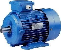
An induction motor used for a pin-type mixer in the fertilizer industry is typically a three-phase motor with a squirrelcagerotor.Themotor'sspecificationswoulddepend onthespecificrequirementsofthemixer,suchasitscapacity, speed,andpowerdemand.Factorslikethetypeoffertilizer being mixed and the mixing process also influence motor selection.The motor's power should be sufficient to drive the mixer under normaloperating conditions, factoring in anyvariationsinload.(20HP)VoltageandFrequencyMatch the motor's voltage and frequency specifications with the localpowersupply. The motor's speed should align with the mixer's requirements for effectivemixing.(1440RPM) The motor's physical size and mounting should fit the mixer's design and spaceconstraints. Consider a highefficiency motor to reduce energy consumption and operatingcosts. Determine the duty cycle (continuous, intermittent, or short-time) to ensure themotorissuitable for the application. Ensure the motor can handle the ambienttemperatureconditionsinthefertilizerproduction environment. Select an insulation class that provides sufficient protection against electricalbreakdown.
4.3 Belt
To choose a V belt fora pin-type mixerin the fertilizer industry,considerthefollowingdetails:
PowerRequirements:Specifythemixer'shorsepower(HP) or kilowatt (KW) rating. This information is crucial for determining the belt's load-bearing capacity. Rotational Speed: Provide the mixer's rotational speed in revolutions perminute(RPM).ThisisessentialforselectingaVbeltwith the appropriate speed rating. Dimensions: Share details aboutthepulleysystem,includingthediametersofthedriver and driven pulleys. This helps calculate the correct belt length and ensures proper power transmission. Ambient Conditions: Describe the environment where the mixer operates. Consider factors like temperature, humidity,and thepresenceofdustorcorrosivematerials.Thisinformation helps in choosing a belt material with suitable resistance Chemical Resistance: If the mixer handles chemicals or corrosivesubstances,specifythetypesandconcentrations.
Thisiscrucialforselectingabeltmaterialthatcanwithstand theseconditions.
4.4 Fly Wheel
Theprimaryfunctionoftheflywheelisto storekinetic energyduringperiodsofexcesspowerandreleaseitduring low-power phases. This helps maintain a consistent rotationalspeedforthemixer,ensuringuniformmixingof fertilizers. Commonmaterialsforflywheelsincludecastiron orsteelduetotheirdurabilityandabilitytowithstandhigh rotationalforces.Thesizeisdeterminedbyfactorssuchas mixer capacity, desired rotational speed, and the need for balancingthesystem. Theflywheelissecurelymountedon the mixer shaft, and its weight distribution is carefully consideredtominimizevibrationsandmaximizestability.It isoftenconnecteddirectlytothemixer'sdrivesystem,either throughadirect mechanicallinkageorothertransmission mechanisms. The flywheel counters variations in power input, ensuring a more constant rotational speed. This is crucial for achieving a homogenous mix of fertilizers. By absorbing excess energy during high-power phases and releasingitduringlow-powerphases,theflywheelhelpsto smoothouttheoverallenergyconsumption.
4.5 Flange Mounted Bearing

Bearings are often made from materials like stainless steelorcastirontoresistcorrosion,whichisimportantinthe fertilizerindustrywherecorrosivesubstancesareprevalent. Robust construction tohandle heavy loads andprovide durability indemanding operatingconditions.Bearingsare designed with specific load capacities in mind. Ensure the selected bearings canhandle the radial and axial loads encountered in your pin-type mixer application. Bearings may incorporate seals to prevent contaminants like dust and moisture from entering,ensuringalongerlifespanand reliableperformance.Sealingoptionscouldincludelabyrinth seals, contactseals, orother specialized designsdepending ontheenvironmentalconditions.
International Research Journal of Engineering and Technology (IRJET) e-ISSN: 2395-0056
Volume: 11 Issue: 04 | Apr 2024 www.irjet.net p-ISSN: 2395-0072
4.6 Pillow Block Bearing
Pillowblockbearingsforpin-typemixersinthefertilizer industryareengineeredtohandletheuniquedemandsofthis application.Thehousing,usuallymadeofrobustmaterials likecastiron,providesasturdysupportstructure.Stainless steelvariantsmaybeusedtoenhance corrosionresistance,
Crucial in fertilizer environments. These bearings are designedwithasealingmechanismtopreventcontaminants from entering and affecting performance. This feature is particularly important in fertilizer production, where particlesandchemicalscouldcompromisetheintegrityofthe bearing. The choice of bearing size and load capacity is determinedbythespecificrequirementsofthemixer.Factors such as the mixer's size, rotational speed, and the forces involvedinthemixingprocessinfluence the selection. It's essential to consult with a bearing expert or the mixer manufacturer to ensure the chosen bearings meet the necessaryspecifications.

4.7 EN8 Pins
Pin type mixers are commonly used in the fertilizerindustryforblendingdifferentmaterialstogether. ThesemixersutilizeaspecifictypeofpinknownastheEN8 pin.TheEN8pinismadefromengineeringsteelthatmeets thestrictrequirementsoftheEN8standard.Thisstandard defines the chemical composition, hardness, and other properties of the steel, ensuring the pin's durability and reliabilityinharshoperatingconditions.

TheEN8steelisamedium-strengthsteelthat offers excellent tensile strength and toughness.It is highly resistant to wear and deformation, making it an ideal material for use in mixer pins. Thedimensions,tolerances, andspecificmechanicalpropertiesoftheEN8pinwillvary dependingonthedesignandrequirementsoftheparticular mixer.Thesespecificationsarecarefullyselectedtoensure optimalperformanceandlongevityofthemixer,whilealso meetingindustrystandardsandregulations.
5. DESIGN
The design process entails the application of scientific principles,technicalknowledge,andcreativeimaginationto developaneworimprovedmachineormechanismtailored to fulfil a specific function with optimal economy and efficiency. Therefore, a meticulous approach to design is imperative.Theentiretyofthedesignendeavourhasbeen dividedintotwosegmentstoensureacomprehensiveand systematicapproach.
5.1 System design
5.2
Mechanical Design.
SystemSystemdesignprimarilyaddressesarangeof factors including physical constraints, ergonomics, spatial requirements,componentarrangementonthemainframe, interactionsbetweenhumansandmachines,controlcount andpositioning,machine'sworkingenvironment,potential failurepoints,safetyprotocols,serviceabilityconsiderations, maintenanceaccessibility,scopeforenhancement,machine weightdistributionfromgroundlevel,overallweight,and more. In mechanical design, components are typically categorized based on procurement and design considerationsintotwomaingroups
1) Designed Parts
2) Parts to be purchased
Forindividuallydesignedparts,adetacheddesignprocessis undertaken,andtheresultingspecificationsarecomparedto theclosestreadilyavailabledimensionsinthemarket.This facilitates assembly and post-production servicing tasks. Tolerances on the components are defined, and process charts are created and transferred to the manufacturing phase.Additionally,partsthataretobeprocureddirectlyare chosen from a variety of catalogues and clearly specified, allowinganyonetopurchasethemfromaretailshopbased ontheprovidedspecifications.
5.1 SYSTEM DESIGN:
In system design, there are several key parameters or considerations that designers typically focus on to ensure the effectiveness, efficiency, and reliability of the system. Theseparameterscanvarydependingonthespecificcontext
International Research Journal of Engineering and Technology (IRJET) e-ISSN: 2395-0056
Volume: 11 Issue: 04 | Apr 2024 www.irjet.net p-ISSN: 2395-0072
and requirements of the system being designed. Here are somecommonparameters:
5.1.1
System Selection Based on Physical Constraints
Whenchoosingamachine,it'sessentialtoassesswhetherit willbedeployedinalarge-scaleorsmall-scaleindustry.In ourcontext,it'sintendedforasmall-scaleindustry,where spaceisacriticallimitation.Therefore,thesystemmustbe exceptionallycompact,allowingittobeaccommodatedina cornerofaroom.
Mechanicaldesignintricatelyconnectswithsystemdesign. Thus, the primary objective is to regulate physical parameters, ensuring that the specifications derived from mechanical design seamlessly integrate into the overall system.
5.1.2
Arrangement of Various Components
Considering space limitations, it's imperative to arrange components in a manner that allows for easy removal or servicing. Additionally, each component should be readily visible,withnonehiddenfromview.Optimalutilizationof every available space is ensured in the arrangement of components.
5.1.3 Components of System
Aspreviouslymentioned,thesystemmustpossessacompact design to enable placement in a room corner. All moving parts should be enclosed within a compact structure. This compact system design results in a robust and weighty structure,whichisadvantageousforstabilityanddurability.
5.1.4 Man-Machine
Interaction
Ensuring theoperator'seaseandcomfort whileoperating the machine is a crucial aspect of design. This involves applyinganatomicalandpsychologicalprinciplestoaddress issuesstemmingfromtheinteractionbetweenhumansand machines.
1. Footleverdesign
2. Evaluation of energy expenditure during foot and handoperation
5.1.5 Chances of Failure
Consideringthelossesincurredbytheownerincaseofany failure is a crucial aspect of design. Safety factors are prioritizedinmechanicaldesigntominimizethelikelihoodof failures. Additionally, regular maintenance is necessary to ensuretheunitremainsingoodcondition.
5.1.6 Servicing Facility
The arrangement of components should facilitate easy servicing,particularlyforthoserequiringfrequentattention, enablingstraightforwarddisassemblywhennecessary.
5.1.7 Scope of Future Improvement
Provisions should be made in the arrangement to accommodate future expansions in the scope of work. For instance, facilitating the conversion of the machine from manual to motor-operated should be easily achievable. Furthermore, the design should allow for the interchangeability of dies and punches to accommodate differentshapesofnotchesorotherrequirements
5.1.8 Height of Machine from Ground
Toensuretheoperator'seaseandcomfort,it'sessentialto determine the height of the machine appropriately. The machineshouldbepositionedslightlyhigherthanthewaist leveltopreventoperatorfatigueduringoperation.Sufficient clearance from the ground should also be provided to facilitateeasycleaning.
Seamless Pipe, a hollow cylindrical conduit, facilitates the mixingoffertilizerwithinitsconfines.
6 Design Calculations
6.1
Seamless Pipe
ForSeamlessPipe, Were,
L=Length,Pi=Load,Di=InternalDiameter,V=Volume,����= TensileStress,Sut=UltimateTensilestress,F.O.S.=Factorof Safety,T=Thickness,etc.
Requiredvolume-0.506��3
Length-5.2Di
Factorofsafety=3
Pi=3Mpa
Sut=390N/����2
Diameterofseamlesspipe-��=��4⁄×����2L
Di=√4��5.5��3
Di=√4×5.065.2��3
Di=0.498
��=498mm
Di=500mm
L=5.2×500
L = 2580 mm
International Research Journal of Engineering and Technology (IRJET) e-ISSN: 2395-0056
Volume: 11 Issue: 04 | Apr 2024 www.irjet.net p-ISSN: 2395-0072
In standard specification 498 mm size not available. Accordingtotheseamlesspipespecificationchart500mm Diametersizedpipeisselected.
Thickness of seamless pipe –
����=������/��.��.��. ����=390/3.
=130N/����2
T=Pi.Di/2����
=3×500/2×130
T=5.7mm
(5.7 mm Thickness is Not Available According to ManufacturingTable)Approximately,thickness
T = 6 mm
6.2 Flywheel:
A flywheel is a mechanical device used to store rotational energy. It consists of a heavy disk or wheel mountedonanaxle,
And its primary function is to store energy in the form of kineticenergy.
Were,
N=Rpm,w=AngularVelocity,��=Density,D=Diameter,���� =Stress,etc.
GivenValues-N=500Rpm,w=2��×500/60=52.33rad/sec, ��=7500Kg/m3,����=2.51mpa
Diameter of the Flywheel-
Let,D=DiameteroftheFlywheelinmeters.Weknowthat theperipheralvelocityoftheflywheel,
��=������/60
=����×500/60
=26.16Dm/s
Wealsoknowthathoopsstress(����),
����=��×��2=2.51×106
=7500×26.16��×26.16D
D2=0.4887m
D=0.699m
=699mm
DiameterConsideredas700mm
D = 700 mm.
Cross Section of the Flywheel-
Let,t=ThicknessofFlywheelRiminmetersand b=widthofFlywheelRiminmeter=0.52t
CrosssectionAreaoftheRim,
A=b×t
A=0.52t×t=0.52t2
Since,thescaleofthecrankangleis1mm=0.46º=0.46× Π/180=0.0081,andthescaleoftheturningmomentis1mm =300N-m,therefore 1mm2ontheturningmomentdiagram
=300×0.0081
=2.44N-m
Maximumenergy=E+442
Minimumenergy=E-32
WeknowthatthemaximumFluctuationofenergy
∆E=Maximumenergy–Minimumenergy =(E+442)-(E-32)=474
=474×2.441
=1157.03N-m.
CoefficientofFluctuationofspeed,
Cs=0.03
Let,m=MassoftheRim.
WeknowthatthemaximumFluctuationofenergy(∆E), 1157=m×v2×Cs
1157=m×18.3162×0.03
m = 114.96 Kg
Wealsoknowthat, themassoftheflywheelRim(m),
m=A×ΠD×ρ
114.96=0.52t2×2.198×7500
t=0.115m
t = 115 mm
b=0.52t
b = 59.8 mm
6.3 V-belt
Design of the belt drive
Given–P=15KW;N1=1440RPM;N2=500RPM;d2=700 mm;x=800����; OverloadFactor=1.3;ρ=1000Kg/m3;T=1.5MPa; µ=0.28;t=12MPa.
Let,P=Power
International Research Journal of Engineering and Technology (IRJET) e-ISSN: 2395-0056
Volume: 11 Issue: 04 | Apr 2024 www.irjet.net p-ISSN: 2395-0072
N1=DriverShaft;D1=DiameterofmotorpulleyN2=Driven Shaft;D2=DiameterOfmixerpulley
x=DistancebetweenTwoShafts.;ϴ=AngleofContactρ= Density;V-Velocity
ς=Load
Firstofall,letusfindthediameter(d1)ofthemotorpulley.
Weknowthat
N1/N2=d2/d1,d1=d2×N2/N1,700x500/1440=243mm= 0.243m
Orsinα=d2-d1/2x=700-243/2(800)=0.2843=16.26°
Weknowthattheangleofcontact,
θ=180°-2α=180-2×16.26=147.28°=147.28xπ/180= 2.56rad
LetT1=Tensioninthetightsideofthebelt,andT2=Tension intheslacksideofthebelt.
Assumethegrooveangleofthepulley,2β=35°orβ=17.5°.
Weknowthat2.3log(T1/T2)=µ.θcosecβ=0.28x2.56x cosec17.5°=2.42
Log(T1/T2)=2.42/2.3=1.0526 (T1/T2)=11.28 ...(Takingantilogof1.0526)
Weknowthatthevelocityofthebelt, v=����1.��1/60=��×0.243×1440/60=18.31m/s
Andmassofthebeltpermeterlength,Let,m=Massofthe belt
m=Areaxlengthxdensity =350x10−6x1x1000 =0.35kg/m
Centrifugaltensioninthebelt, Let,Tc=CentrifugalTension
Tc=m.��2=0.35(18.31)2=117N
Andmaximumtensioninthebelt,
T=Stressxarea=1.5x350=525N
Tensioninthetightsideofthebelt,
T1=T-Tc=525–117=408NT2=T1/11.28=408/11.28= 36.17N
Weknowthatthepowertransmittedperbelt, =(T1-T2)v =(408–36.17)18.31 =6808W =6.808kW.
Sincetheoverloadfactoris1.3,thereforethebeltistobe designedfor1.3x15=19.5kW.
Number of belts required = Designed power /Power transmittedperbelt
=19.56.808=2.86say3.
No. of Belts = 3
SincetheV-beltistobedesignedfor19.5kW,thereforefrom DimensionOfSlandered V-beltsTable,CSection=PowerRangeis(7.5–75kw).
wefindthata'C'typeofbeltshouldbeused.
Let,L=Lengthofthebelt
Weknowthatthepitchlengthofthebelt,
L =π(r2+ r1) +2x+(��2−��1)2/x =π2(d2+d1)+ 2x+ (d2−d1)2/4x
=(700+243)+2x800+(700−243)2/4(800)
=943+1600+65
=2608mm
Adding8mmfor'C'typebelt,wefindthatOutsidelengthof thebelt
=2608+8
=2616mm
According to IS: 2494 – 1974, the nearest standard inside lengthofV-beltis2616mm.
AccordingtotheCsectiontableDimensionis–
i. Belt No - C103.
ii. Thickness -17/32 in.
iii. Top width – 7/8 in.
iv. Inside length – 103 in.
6.4 Mixer Shaft:
LetD=Diameteroftheshaft.
WeknowthatthetorquetransmittedbythedrivenorMixer pulleyshaft,
T=DesignedPowerx60/2.����2
=19500x60/2x��x500
=372N-m
=372×10N-mm
Since the overhang of the pulley is 300 mm, therefore bendingmomentontheshaftduetothebelttensions,
M=(T1+T2+2Tc)300×3 ...(No.ofbelts=3)
=(408+36.18+2×117)300×3=610.62×10³N-mm
∴Equivalenttwistingmoment,
International Research Journal of Engineering and Technology (IRJET) e-ISSN: 2395-0056
Volume: 11 Issue: 04 | Apr 2024 www.irjet.net p-ISSN: 2395-0072
Te=√T2+M2=√(372×103)2+(610.62×10³)2 =715×103N-m
Wealsoknowthatequivalenttwistingmoment
(Te),715×103=π/16x12xD3=2.35D3
D3=715×103/2.35=304×103
D=67.3mmsay68mm
D=68mm.
Designforkey
The standard dimensions of key for a shaft of 68 mm diameterare
Widthofkey=22mm and Thicknessofkey=12mm
7 Working
Agglomerationthroughtumblegrowthisawidelyused process,andthepinmixeroperatesonthesameprinciplesas otheragglomerationequipment.Theprocessinvolvesusing motionandbindertoformagglomerates,butthepinmixer's unique operating theory has three structurally undefined zones that work together to ensure efficient mixing, pelletizing,anddensificationprocesses.Thepinmixerrelies onthecoalescenceeffect,whichoccurswhenliquidbinderis addedtothemixture,makingthefinesstickyandallowing themtopickupadditionalfinesastheytumble.Thisprocess leads to the growth of pellets in size, making them more suitable for their intended use. The type and amount of material and binder used have a significant impact on the qualityofthefinalpelletproduct.Thepinmixer'soperating theory centers around three zones, each playing a specific roleintheagglomerationprocess.Thefirstzoneisthemixing zone,wherethematerialisthoroughlymixedwiththeliquid binder.Thesecondzoneisthedensificationzone, whichis responsible for compressing the mixture and removing excessmoisture.Thethirdzoneisthepelletizingzone,where thepelletsareformedandthendischargedfromthemixer. The pin mixer's unique operating theory ensures that the agglomeration process iscarried out efficiently, producing high-qualitypelletsthatmeetthedesiredspecifications.
7.1 Zone 1 Mixing
In the first 15-20% of the mixer process, the feed componentsaremixedtocreateahomogeneousmixtureof solid and liquid feed materials. This is achieved through a combinationofmechanicalandaerodynamicforces,which causefineparticlesanddropletsofliquidbindertocollide witheachother.Duringthisphase,themechanicalactionof the mixercreatesshear forces thatbreak upanylumpsor clumps of feed material, while the aerodynamic forces createdbythemixer'simpellersmovethefeedcomponents around the mixing chamber and promote mixing. As the mixingprocesscontinues,themixturestartstoagglomerate
andformpellets.Thishappenswhentheliquidbinderstarts tocoatthesolidparticles,causingthemtosticktogetherand form larger particles. The resulting pellets are easier to handleandtransport,andcanbemoreefficientlyprocessed furtherdowntheproductionline.
7.2 Zone2 Pelletizing
Asthemixtureflowsthroughthelengthofthemixer,the individualparticlesstarttobecometackyandagglomerate, forminglargerpellets.Thesepelletsconsistoflooseparticles andcontinuetogrowinsizeastheymovethroughthemixer. The centrifugal force, generated by the mixer's rotation, causesthepelletstorolldownandalongthemixer'sinterior, encouraging the joined-together particles to morph into sphericalpellets.
Asthepelletsform,theymoveawayfromtheinlet,andthe additionofnewmaterialgraduallydecreases.Inthiszone,the densification of particles occurs as the pellets continue to form and grow in size. The spherical shape of pellets is a result of the continuous rolling motion, causing the agglomeratestomaintainauniformshapeandsize.
7.3 Zone3 Densifing
During the pillarization process, larger pellets create Additionalcentrifugalforceinthemixer,whichresultsina shift from formation to densification without any new materialbeingadded.Inthiszone,theinteractionbetween thepelletsandthemixer'sinteriorshellandpins,aswellas between the pellets themselves, causes the pellets to gain density.Thewaterandairvolumewithineachpelletisforced out, leading to densification. Additionally, the pellets are polishedastheyrollagainstthemixer'sinteriorshell,further enhancingtheirappearance.
Once the densification process is complete, the pellets are dischargedfromthemixer.Thesepellets,commonlyreferred to as micro pellets, are uniform in makeup and physical characteristics.Theyarealsoreadyforfurtherprocessingor product finishing since they exhibit a smooth surface and uniform size. The micro pellets can be dried, coated, or subjectedtoadditionalprocessingasnecessary.Overall,the pillarizationprocessresultsinhigh-qualitymicropelletsthat exhibitexcellentcharacteristics.
8. CONCLUSIONS
As benefits of the continuous pin type mixer in the contextofthefertilizerindustry Theintricatedesignofthe continuouspintypemixerinvolvesstrategicallyplacedpins withinthe mixing chamber, promoting intricate material intermingling. This design ensures not only ahigh level of homogeneitybutalsoaddresseschallengesassociatedwith variousparticlesizesandshapespresentinfertilizers.The resultisafinelyblendedmixturethatmeetsstringentquality standards.Moreover,themixer'sadaptabilityextendstoits
International Research Journal of Engineering and Technology (IRJET) e-ISSN: 2395-0056
Volume: 11 Issue: 04 | Apr 2024 www.irjet.net p-ISSN: 2395-0072
abilitytohandlebothgranularandpowderedcomponents, accommodating the diverse nature of fertilizers. The consistentblendingachievedbytherotatingpinsmitigates theriskofunevendistributionofnutrients,fosteringamore uniformendproduct.Thisiscrucialinthefertilizerindustry, whereprecisenutrientratiosdirectlyimpactcropyieldand quality.
Thecontinuousoperationaspectofthemixerispivotal in optimizingproductionworkflows.Byeliminatingtheneed for frequent starts and stops, it minimizes downtime, contributingtoenhancedoverallefficiency.Thetimesaved intheblendingprocesstranslatesintoincreasedthroughput, a valuable advantage in a sector where production volumes often play a critical role in competitiveness. Furthermore,themixer'sdesignfacilitateseasycleaningand maintenance, crucial aspects in industries dealing with variouschemicalcompounds.Thiseaseofmaintenancenot only ensures the longevity of the equipment but also supports adherence to industry regulations and quality standards.
In conclusion, the continuous pin type mixer, with its intricate design, adaptability, and operational efficiency, emerges as a cornerstone technology in the fertilizer industry. Its role inachieving precise material blending, minimizing downtime, and facilitating maintenance underscores its significance as a catalyst for improved productivity and quality in fertilizer manufacturing processes.
9. FUTURE SCOPE
Theauthorsthefuturescopeofcontinuouspin-type mixersinthefertilizerindustryismultifaceted.Thesemixers, known for their ability to achieve thorough blending of diversefertilizercomponents,offerseveraladvantages.
9.1 Efficiency and Homogeneity: Continuous pin-type mixers ensure a consistent and homogeneous mixture of ingredients,enhancingtheoverallqualityoffertilizers.This is crucialforachievingprecisenutrient distributioninthe finalproduct.
9.2 Increased Production Speed: Thecontinuousnatureof these mixers allows for a seamless and uninterrupted blending process. This leads to higher production speeds, contributing to increased overall output and efficiency in fertilizermanufacturing.
9.3 Energy Efficiency: Asindustriesstriveforsustainability, the energy efficiency of equipment becomes paramount. Continuouspintypemixers,withtheirstreamlineddesign andcontinuousoperation,cancontributetoreducedenergy consumptioncomparedtobatchmixingmethods.
9.4 Adaptability to Various Formulations: Theflexibility of continuous pin type mixers makes them suitable for
handling a wide range of fertilizer formulations. This adaptability is essential in an industry where diverse product formulations may be required to meet specific agriculturalneeds.
9.5 Quality Control and Consistency: Thesemixersenable precisecontrolovertheblendingprocess,ensuringthateach batch meets stringent quality standards. Consistency in fertilizer composition is crucial for delivering reliable agriculturalresults.
9.6 Integration with Smart Manufacturing: Asindustries embrace Industry 4.0 and smart manufacturing practices, continuous pin type mixers can be integrated with digital systemsforreal-timemonitoring,dataanalysis,andprocess optimization.
9.7 Environmental Considerations: With an increasing focusonsustainablepractices,continuousmixersalignwell with efforts to minimize waste and optimize resource utilization.
Insummary,thefuturescopeofcontinuouspintypemixers in the fertilizer industry lies in their capacity to enhance efficiency,reduceenvironmentalimpact,andalignwiththe industry's evolving demands for sustainable and highqualityfertilizerproduction
10. REFERENCES
[1] Bennett,Dealey,&Posnett“costofpressureulcer”,vol. 33no.3britishgeriatricssociety2004;2004.
[2] Jozef Hužvár, MSc. Eng. Patrik Nemec University of Žilina
[3] National aeronautics and space administration heat pipedesignhandbook,volume1,June1979.
[4] Yang X., Yan Y., & Mullen D. Applied Thermal Engineering33–34(1):1–14·February2012.
[5] John Chato, "Analytical Solutions to the Problem of Transient Heat Transfer in Living Tissue",December 1971.
[6] DavidReayRyanMc GlenPeterKew,Theory,Design andApplications,8thNovember2013.
[7] AvrahamShitzer,"Designofheatpipe",1984.
[8] Heat-related issues and practical applications for ParalympicathletesatTokyo2020
[9] T.P.HignettManufactureofgranularmixedfertilizers
[10] P.J. Sherrington The granulation ofsand as an aid to understanding fertilizer granulation Chem. Eng. (London)(July/Aug.1968)
International Research Journal of Engineering and Technology (IRJET) e-ISSN: 2395-0056
Volume: 11 Issue: 04 | Apr 2024 www.irjet.net p-ISSN: 2395-0072
[11] S. Nordengren Granulation of phosphate fertilizers –theory and practice Proc. Fertil. Soc. London(1947)
[12] J.O.HardestyGranulation,Chapter11Superphosphate: ItsHistory,ChemistryandManufacture(1964)
[13] H.B.RiesBuild-upgranulationAufbereit.-Tech.(1971)
[14] H.B. Ries A modern plant for the production of granulatedmixedfertilizerAubertite.-Tech.(1975)
[15] J.W.Renneburg,RenneburgInternationalInc.,private communication,August15
[16] D.F.Balletal.AgglomerationofIronOres(1973)