
International Research Journal of Engineering and Technology (IRJET) e-ISSN: 2395-0056
Volume: 11 Issue: 04 | Apr 2024 www.irjet.net p-ISSN: 2395-0072
International Research Journal of Engineering and Technology (IRJET) e-ISSN: 2395-0056
Volume: 11 Issue: 04 | Apr 2024 www.irjet.net p-ISSN: 2395-0072
Prasen .N. Sanap, Mauli .S. Devmunde, Bipin .S. Gadge, Omkar .S. Mehetre, Prof. V.M. Mhaske
Prasen .N .Sanap, Department of Mechanical Engineering, Amrutvahini College of Engineering, Sangamner, Maharashtra, India
Mauli .S. Devmunde, Department of Mechanical Engineering, Amrutvahini College of Engineering, Sangamner, Maharashtra, India
Bipin .S. Gadge, Department of Mechanical Engineering, Amrutvahini College of Engineering, Sangamner, Maharashtra, India
Omkar .S. Mehetre, Department of Mechanical Engineering, Amrutvahini College of Engineering, Sangamner, Maharashtra, India
Prof. V.M. Mhaske, Department of Mechanical Engineering, Amrutvahini College of Engineering, Sangamner, Maharashta, India ***
Abstract - The automobile chassis is the foundation for internal components and external loads, influencing vehicle performance. Advancements in design and construction have improved speed, handling, safety, and fuel economy. The evolution of chassis systems, originating from Henry Ford's assembly line, has been marked by technological leaps, particularly in lightweight materials and innovative designs. This research aims to provide insight for student teams in automotivecompetitions,facilitatingthecreationofefficient, high-performance chassis for hybrid electric vehicles, by examining various materials and design approaches.
Key Words: Hybrid electric vehicle, Chassis, Design, Manufacturing,analysis,testing,MaterialSelection,Impact Analysis.
The automobile chassis is the structural foundation of a vehicle.Itisthemainsupportingsystemofthevehiclewhich supports the internal components of the vehicle and also sustains the load acted upon it due to this integrated componentandalsotheextraweightputtedonthevehicle. Theautomobilechassisplayanimportantroleindeveloping the vehicle and the performance factors that would be achieved by a automobile. Its design and construction influencethevehicle'shandling,ridecomfort,anddurability. Duetocertainadvancementinthedevelopmentofchassis systemtheperformancefactorslikespeed,handling,safety, fueleconomyhasbeenimprovedconsiderably.Thechassis framesupportsthevariouscomponentsandthebodyand keepsthemincorrectpositions.Ourattemptisnotentirely correctwaytodesigna chassissystem,butit isanhonest efforttodesignachassisforaHybridElectricVehicle(HEV).
As we know that Automobile Industry is an evergreen industryandithasseenseveraladvancementsinrecenttime.
At the time of the first Mass Production Assembly Line StartedbythegreatHenryFordonDecember1st1913.From that time several automobile manufacturers are trying differentthingsandintroducingseveraltechnologiesinorder toincreasetheproductionandtomaketheirvehiclesmore durableandpowerful.Onesuchsystemthathaveseenaswift technological and manufacturing advancement is the Roll Cage or Chassis system. The chassis of an automobile has been an important part for the manufacturing companies sinceitsupportsalltheothercomponentsthataretobefitted intothevehicle,Itwaslikethefoundationofthemainvehicle. In order to make the foundation strong several materials, different shapes of the materials, and different types of chassiswasused.Thisallfactorsresultedinimprovementof the chassis and due to which the vehicle became more durable and robust, but as the time passed several performancefactorswasdemandedfromtheautomobileby the people,like better fuel consumption,Increasingspeed, moreaerodynamicshape,overalllightweightvehiclethisalldemandleadtothedevelopmentofchassissystem.Several light weight materials were tested in order to replace the heavymaterialssotheoverall weightofthevehiclewould reduce,whichwouldresultinbetterfuelefficiencyandbetter speed. Some material of equal strength but of less weight thantheoriginalmaterialswereused.Also,differenttypesof chassis system were developed like single frame ladder chassis, double frame ladder chassis, tubular chassis, monocoquechassisetc.
1.2
in current model(from analyzing current model)
Theautomobilemarkethassignificantlychanged,withthe replacement of conventional petrol and diesel vehicles by electricvehicles(EV)andhybridelectricvehicles(HEV).The manufacturinganddesignapproachesofthesevehiclesare evolvingtomeettheneedforpollution-freevehicles.HEVs aimtoprovidemaximumrangewithlowfuelconsumption, makingweightakeydesignparameter.Manufacturersare
International Research Journal of Engineering and Technology (IRJET) e-ISSN: 2395-0056
Volume: 11 Issue: 04 | Apr 2024 www.irjet.net p-ISSN: 2395-0072
working to reduce chassis weight by using different materials,withsomeachievingthisgoal.Thiseffortaimsto create a chassis that supports various components and sustainstheloadappliedonit,ensuringefficientrangeand lowfuelconsumption.Overall,thedevelopmentofEVsand HEVsiscrucialfortoday'sworld
From this project the student teams that are participating intodifferentcompetitionwillgetanideaaboutthedifferent materialsthatcanbeusedtomanufacturechassisandhowto deliberatelydecreasetheweightofthechassiswhichwould ultimatelydecreasetheweightofthewholevehicle,alsothey didn’tneedtocompromiseonthesafetyparametersandthe overallstrengthofthechassissystem.
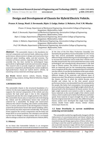
FIG.1.LayoutofChassis
ThePrimaryStructureiscomprisedofthefollowingFrame components:
1. Main Hoop -Arollbarlocatedalongsideorjustbehind thedriver’storso
2. Frame Member - A minimum representative single pieceofuncut,continuoustubing.
3. Front Hoop -Arollbarlocatedabovethedriver’slegs, inproximitytothesteeringwheel
4. Front Bulkhead –Aplanarstructurethatdefinesthe forwardplaneoftheMajorStructureoftheFrameand functionstoprovideprotectionforthedriver’sfeet.
2.1 PROBLEM STATEMENT
To Design a lightweight Tubular chassis for urban Hybrid Electric Vehicle, which Sustain given load and Prioritize DriversSafety.
2.2 OBJECTIVE
o Select materials from Design Data Book based on strength,durability,andcost,formaximumstrength-to weightratio.
o Studyofdifferentshapesandcrosssectionofthechassis.
o DesignandFabricationofdurableandreliableChassis.
o Modellingandanalysisofchassis.
o Testing of Chassis in various Static and Dynamic conditions.
1. Chassis Components and Parameters:
Component Identification: This includes listing all the componentsthatthechassiswillsupportandintegrate.This includestheengine,transmission,suspension,bodypanels, andotheradditionalsystemsspecifictothevehicle'spurpose (suchasabatterypackforanelectricvehicle).Thisincludes its dimensions (length, width, height), weight distribution and attachment points. Software like AutoCAD or CATIA helpsvisualizeinsertionandremoval.
2 Chassis Design:
ComputerAidedDesign(CAD):Createadigitalimageofthe chassisusing3DmodelingsoftwaresuchasSolidWorksor Creo.Here,engineersconsiderthelocationofcomponents, theirdimensions,andhowtheywillbeintegratedintothe entire structure. CAD models allow visualization, dimensionalanalysisandeffectsofcomponents.
3. Material selection:
Materialselectionaffectscaseperformance,weightandcost. Options include steel (high strength, suitable for conventionalvehicles),aluminum(lightweight,suitablefor high-end vehicles) and carbon fiber (very light, used in expensive, high-end parts). Important factors to consider are: Strength and stiffness: The material must withstand forces during operation (speed, stop, angle) without excessivedeformation.andmaneuverability.Equipmentcost isespeciallyimportantforlargervehicles.
4. Stress Analysis:
Finite Element Analysis (FEA) software like ANSYS or Abaqusisusedtosimulatethestressesandstrainsthatthe chassis will experience under various loading conditions. The3DCADmodelisvirtuallydividedintosmallelements, andcomputercalculationspredicthowtheseelementswill deform or break under applied loads. This analysis helps identifyweakpointsinthedesignandoptimizethematerial distributionformaximumstrengthandweightefficiency.
5. Physical inspection:
Prototypedesign:Thephysicalmodelofthechassiscanbe designed based onthecompletedCADmodel.Themodels arethensubjectedtorigoroustestingthatmimicsreal-world conditions:
Static load test: simulates the weight of the vehicle and cargo.
International Research Journal of Engineering and Technology (IRJET) e-ISSN: 2395-0056
Volume: 11 Issue: 04 | Apr 2024 www.irjet.net p-ISSN: 2395-0072
Crashtest:Testthechassis'abilitytoprotectpassengersin the event of a crash. Any differences will indicate an area wherethedesignmayneedtobechanged.
6. Production:
ProductionPlanning:Oncethedesignisverifiedbytesting, the production process can be planned. This includes selecting the appropriate manufacturing process (such as welding, riveting, assembly) and ensuring that the chosen methodiscompatiblewiththeselectedproduct.
TheFrameneedstowithstandanycollisionthatitmightbe subjectedtoaspartofthetestingprocessorcompetition. Four impact scenarios were analyzed to ensure the frame designwillnotfail.
FrontImpactTest.
RearImpactTest.
SideImpactTest.
RolloverTest.
( Note: AllofthistestaredoneinANSYS.)
The vehicle is designed for maximum speed of 80 km/ph. The total weight of the vehicle including the driver is estimatedtobe320kg.Itisconsideredforthestaticanalysis that the vehicle comes to net 1 sec after the impact. The Boundaryconditionsforthistestare
Inthiscasethevehicleisassumedtobeinrestconditionand the vehicle of same mass is assumed to collide with our
vehicle with the speed of 80 km/Ph, and we observe the maximumdeformationinthatcondition.
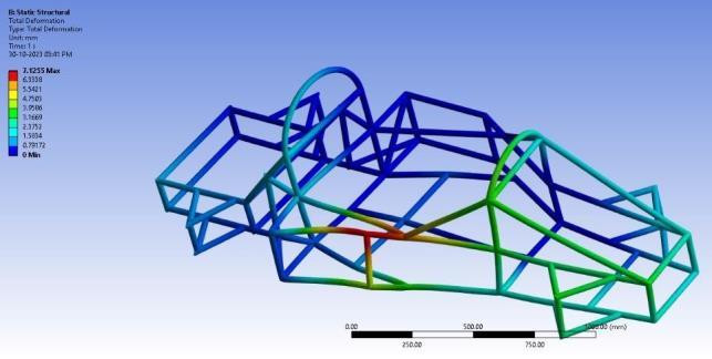
Fig.4showstheSideImpactTestinwhichtheVehicleisin Rest Position and the vehicle of same specifications and samemassisassumedtocollidewithourvehiclesideways sointhisconditionthemaximumdeformationisnotedand studiedupon.
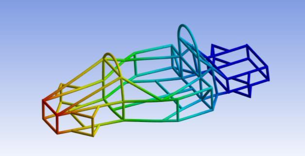
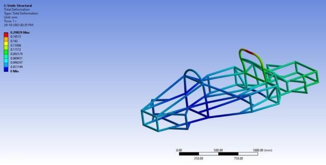
AftertheFront,Rear,andSideImpacttestwePerformthe last type of test i.e. Vehicle Rollover test. In this test we assume the vehicle rollover condition and the position of vehicleischangedandthemaximumforcegetsexertedon themainhoopsBracing.
RESULT TABLE:
Sr. No Scenario Boundary Condition Results
1. FrontImpact Test Velocity–80kmph (Max.Def. =27.534 mm) (F.O.S. =2.3867)
2. Rear Impact Test Force=22204 N Max.Def.=10.179m m)(F.O.S.=2.7433)
3. SideImpact Test Force=9417N (Max.Def. = 7.1255 mm)(F.O.S.=3.237)
4. RollOverTest Force=6270N (Max.Def. = 0.2082 mm) (F.O.S. = 3.897)
TableNo.1
International Research Journal of Engineering and Technology (IRJET) e-ISSN: 2395-0056
Volume: 11 Issue: 04 | Apr 2024 www.irjet.net p-ISSN: 2395-0072
Thestudyonthedesignandmanufacturingofalightweight tubularchassisforanurbanHybridElectricVehicle(HEV) hasprovidedsignificantinsightsintotheevolutionofchassis systems in the automobile industry. The research highlighted the importance of chassis as the structural foundationofavehicle,withadvancementsmadetoimprove performance, safety, and fuel efficiency. The study also highlightedtheimportanceofmaterialselectionanddesign optimization, with CAD modeling and Finite Element Analysis(FEA)simulationshelpingoptimizethedesignfor maximumstrength-to-weightratio.Thechassisunderwent comprehensive testing, including static load tests, impact scenarios, and roll-over tests, providing valuable insights into its performance under different conditions. The designed lightweight tubular chassis demonstrated enhancedperformanceattributes,suchasimprovedspeed, handling, and fuel economy, contributing to the efficiency andsustainabilityofhybridelectricvehicles.Theprojectalso servesasavaluableresourceforstudentteamsparticipating inautomotivecompetitions,offeringinsightsintomaterial selection, design methodologies, analysis techniques, and testing protocols. Overall, this research contributes to ongoing advancements in automotive engineering, particularly in sustainable mobility solutions and the transitiontowardselectricandhybridvehicles.
We would like to express our sincere gratitude and appreciation to all those who have contributed to the successfulcompletionofthisprojectandthepreparationof thisreport.
Firstandforemost,weextendourheartfeltthankstoProf.V. M. Mhaske, our esteemed project guide, whose guidance, expertise, and continuous support were instrumental in shaping this research endeavor and providing valuable insightsthroughouttheprojectduration.
WearegratefultothemanagementofAmrutvahiniCollege ofEngineering,Sangamner,representedbyM.A.Venkatesh, our Principal, for providing the necessary infrastructure, resources,andencouragementtoundertakethisprojectand for fostering an environment conducive to academic and researchexcellence.
We also acknowledge the support and encouragement received from V. D. Wakchaure, Head of the Mechanical Department,forhisvaluableinputsandguidance.
Oursincerethanksalsogotoallthefacultymembersofthe MechanicalDepartmentfortheirsupport,encouragement, andvaluablefeedbackduringthecourseofthisproject.
Lastly,weextendourappreciationtoourpeers,friends,and family members for their understanding, encouragement, and unwavering support throughout this academic endeavor.
Their collective contributions have been invaluable in the successfulcompletionofthisprojectandthepreparationof thisreport.
[1] Practicalfiniteelementanalysis:-(nitins.gokhale)
[2] Race car vehicle dynamics:-(william f. Milliken and Douglassl.Milliken)
[3] Theautomotivechassis:engineeringprinciples(second edition)
[4] Static Structural analysis of REEV Chassis: https://www.ijariit.com/manuscript/static-structuralanalysis-of-sae-baja-chassis/
[5] Design and Analysis of Chassis for SAE REEV Vehicle, (August2019) https://www.iosrjournals.org/IOSRJEN.html.