
International Research Journal of Engineering and Technology (IRJET) e-ISSN: 2395-0056
Volume: 11 Issue: 04 | Apr 2024 www.irjet.net p-ISSN: 2395-0072
International Research Journal of Engineering and Technology (IRJET) e-ISSN: 2395-0056
Volume: 11 Issue: 04 | Apr 2024 www.irjet.net p-ISSN: 2395-0072
Nandini Naresh Raut1 , Nimish Patankar2 , Prof. Pallavi Nikhil Bhende 3
1 M.Tech Computer Aided Structural Engineering Student WCEM, Nagpur 2Structural Engineer, RCC and steel structural Consultant, Nagpur
3Head of Dept. of civil Engineering WCEM, Nagpur
Abstract - Because of the current circumstances, which includes a growing population, expanding cities, and uneven terrain, most buildings are usually constructed on sloping terrain. The distribution of mass and stiffness in both the horizontal and vertical planes varies when a building is situated on a sloping site. These structures are susceptible to severe damage from ground motion during an earthquake because they are frequently torsional linked and situated on steep hillsides in seismically active areas. Model analysis software is done using ETABS 16. On both level and sloping surfaces, models are assessed.First, the modelis subjectedtoa seismicanalysis procedure that entailsallocatingvariousload scenarios and combinations. Among the study's findings are maximum storey displacement, overturning moment, storey drift, and storey shear. For structures of various heights, the dynamic response basic time period, storey displacement, andbase shear actioncausedincolumns hasbeenexamined. As is well known, reinforced concrete structures built on mountain slopes frequently have asymmetrical shapes with downward gradients, making them vulnerable to severe damage duringearthquake activity. The aimofthis studyisto conduct a comparative examination of the results obtained from the dynamic method of earthquake analysis on reinforced concrete structures with five distinct forms, including ordinary buildings. Analysis that includes storey shear, storey drift, and storey displacement in the X and Z dimensions.
Key Words: - Seismic Analysis, ETABS 16, Sloping ground
Theeconomicgrowth&rapidurbanizationinhillyregionhas accelerated the real estate development. Asaresult,thehillyregion'spopulationdensityhassignifican tlyexpanded.Insteepareas,adobeburntbrick,stonemasonr y,anddressedstonemasonrystructuresaretypicallyconstru ctedonlevelterrain.Sincelevellandinhillyregionsisvery limited,thereisapressingdemandtoconstructbuildingson hill slope. Hence construction of multi-story R.C. Frame buildings on hill slope is the only feasible choice to accommodateincreasingdemandofresidential&commercial activities.Earthquakesarethenaturalphenomenon’swhich arecausedbythereleaseoflargestrainenergybythemoving faults below the surface of the earth, the lateral force
amplitudes and intensities causing the earth's surface to trembleinallpossibledirections.
Oneoftheworld'smostseismicallyactiveareasistheIndian Himalayas, which run from Nagaland in the northeast to Kashmirinthenorthwest.TheIndianZonationmapplaces theentireareaunderseismiczonesIVandV.Thedemandfor multi-storyReinforcedConcrete(RC)buildingshassurged over the existing local traditional constructions in hilly regionsduetorapidurbanizationandpopulationgrowth.But becausethemajorityofthesestructuresarenotengineered, theyhaveagreatdealofissues,suchaslowmaterialquality, inadequateseismicdetailinganddesign,anddisconnected vertical andhorizontal building elements.During previous earthquakes,suchasthe2005Kashmirearthquake,the2011 Sikkim earthquake, and the 2015 Nepal earthquake, significantdamagewasnotedinthesebuildings.
Naturalperiodofabuildingisonesuchimportantdynamic property,whichhasitskeyroleduringthedesignphaseof the construction of a building. The fundamental natural periodofabuildingisoneofthesignificantparametersthat isusedtocalculatethedesignbaseshearandlateralforces actingonabuilding,whichareusedinthedesignprocedures. But as this building property cannot be computed for a structureduringtheinitialstagesofdesign,buildingcodes provide empirical formulas to calculate the approximate valuedependingonthebuildingmaterial[steel,reinforced concreteetc.],structuralsystem(frame,shearwall,etc.),and overall dimensions. But the existing expressions of fundamental natural period of a building prescribed by IndianSeismiccodeIS1893:2016areadoptedfromearlier versionsofUScodeswhichareoriginallydevelopedbasedon response of buildings founded on flat ground during Californianearthquakes.
2.1 Prashant D, et al. (2013) - "SeismicReactionofRC Frame One-Way SlopeBuilding with Soft Storey" [1]. The buildingsituatedonahillsidewitha27°horizontalslopeis studiedtofindouthowthesoftstoreyimpactstheresponse
International Research Journal of Engineering and Technology (IRJET) e-ISSN: 2395-0056
Volume: 11 Issue: 04 | Apr 2024 www.irjet.net p-ISSN: 2395-0072
ofthestructure.Thepresentpaperinvestigatesperformance based seismic evaluation of building models namely: bare frame, soft storey, fully infill buildings with unreinforced masonryinfillforG+9storieslocatedinseismiczoneV.The addition of masonry infill walls to the ground storey efficientlyminimizesthestoreydriftofsoftstorey;baseshear increasesasbuildingstiffnessincreases.Thenaturalperiod decreases as the stiffness of the building increases and thereby leadingto increase in baseshear. Analysis reveals that,incomparisontoothermodels,thebareframemodel's timeperiodisroughly90to135percentlonger.
2.2 Umakant Arya, et al. (2014) - “Wind Analysis of Building Frames on Sloping Ground” [2]. In this research paper,theeffectofwindvelocityandstructuralresponseof building frame on sloping ground has been studied. Considering various frame geometries and slope of grounds.Maxaxialforceinbeamsincreaseswithincreasein thegroundslopes.Maxaxialforceinbeamismoreaffected forslopinggroundandwindvelocityonbuildingframe.Max axialforceincolumnincreaseswithincreasesintheheightof building frame.Max shear force in beams increases with increaseintheheightofbuildingframeonslopinggroundas well as plane ground.Max moment in beams for different buildingheightsincreaseswithincreaseinthewindvelocity. Maxmomentinbeamsdoesnotgetaffectedbyincreasein the ground slope. Ax moments in column increases with increaseintheheightofbuildingframe.
2.3 Narayan Kalsulkar, et al.(2015)-“SeismicAnalysis of RCC Building Resting on Sloping Ground with varying NumberofBaysandHillSlopes”[3].Inthispaper48models with step back structural frame are studied on account of higherstorydisplacement.Stepback-setbackframesresult inlessbaseshearthanstepbackframes.Themostdamaged columns are found to be the extreme left ones, which are shortandlocatedonthehighersideoftheslopingland.The performanceofstepback framesduringseismicexcitation could prove more vulnerable than other configurations of buildingframes,hencestepback-setbackframesaremore desirablethanstepbackframes.Asnumberofbaysincreases timeperiod&topstoreydisplacementdecreases.Therefore, itisconcludedthatgreaternumberofbaysareobservedto be better under seismic conditions. The top story displacementdiminishesandthetimeperiodincreaseswith hillslopes
2.4 Anjeet Singh Chauhan, et al. (2021) -“Seismicresponse ofirregularbuildingonslopingground”[4].Inthispaper,a G+10 RCC Stepback building having each storey of height 3.6mwithahorizontalangleofinclination20°,30°,40º,and 45Model-1.StepbackBareFrame.Model-2.StepbackBare FramewithMassIrregularity.Model-3.StepbackBareFrame withDiaphragmIrregularity.Model-4.StepbackBareFrame with Mass & Diaphragm Irregularity. As the angle of slope increasetheneveryModelframesofModeperiod,Baseshear, Storeydisplacement,andstoreydriftvaluesincreasesinboth
directions,butinthecaseofstoreyshear,itsvaluesdecrease inbothdirectionsofeachModelframesastheangleofslope increases. Baseshearand storey shear ofModel-1 is more than 14.60% and 19.37% in X-direction and 10.80% and 21.98%inY-directionofModel-4.Storeydisplacementand storeydriftofModel-1islessthan3.49%and4.62%intheXdirectionofModel-4.Oncomparisonanddynamicresults,it is observed that Model-2 found maximum mode period, storey displacement and storey drift at 45° from other models. On the comparison of models, it is found that the performanceofstepbackbareframewithmassirregularity (Model-2) during seismic excitation could prove more vulnerable on 45° slopes than another Model frame. On comparisonanddynamicresults,itisobservedthatModel-3 found minimum mode period, storey displacement and storeydriftat20°fromothermodels.
2.5 Pawan Pawar, et al. (2023) -Acomparisonbetweena multi-storeybuildingrestingonalevelandslopinggroundin termsofseismicanalysis[5].Thepurposeofthispaperisto analysis G+8 storey building on the basis of shear wall analysisinsetbackstructuralframebuilding,fromthispaper it is concluded that-Combination with shear wall shows minimumbaseshearascomparedtoother. Shearwallhave great effect to resist lateral displacement of building as comparedtomainmodels.Buildingcombinationwithshear wallshowsminimumAbsolutedisplacementascomparedto other. The building combination with shear wall shows minimumresultsascomparedtoanotherbuilding. Inclined fromfront-setbackbuildingframeshowsminimumresults ascompared to other building Hence Inclined from frontsetbackbuildingframeisbetterascomparedtoother.
2.6 Prasad Ramesh Vaidya. (2015)- “SeismicAnalysis of Building with Shear Wall on Sloping Ground” [6]. The seismic performance of shear wall buildings on sloping terrain is examined in this study. The principal aim is to comprehendthebehaviorofthestructureonslopingterrain for different shear wall placements and to investigate the efficiency of shear walls on sloping terrain. Shear wall placement is crucial for buildings on sloping terrain to withstandseismiceffects.Themostimportantcomponentof aconstructiononslopingterrainareshortcolumns.Themost importantcomponentofaconstructiononslopingterrainare the short columns. To have a good control over the forces suchasshearforceandbendingmomentitispreferableto locate the shear wall towards the shorter column side. Bendingmomentandshearforcealongslopingsideisfound to be minimum for shear wall towards shorter column, whereasonothersideShearwalllocatedsymmetricallyin plangivesminimumshearforceandbendingmoment.
2.7 D. J. Misal, et al. (2016) - “Study of Seismic Behaviours of Multi-Storied R.C.C. Structures Considering Bracing Systems and Resting on Sloping Ground" [7].The study of these vibrations by various techniques, understandingthenatureandvariousphysicalprocessesby
International Research Journal of Engineering and Technology (IRJET) e-ISSN: 2395-0056
Volume: 11 Issue: 04 | Apr 2024 www.irjet.net p-ISSN: 2395-0072
applyingthebracings.Itisexplainedthattheshortcolumnis stiffer as compared to tall column and it attracts larger earthquakeforce.Stiffnessofacolumnmeansresistanceto deformationthelargeristhestiffness,largerforcerequired todeformit.AsperIS1893(Part-1)-2002buildingswithdual systemconsistofshearwallsorbracingframessothatthese are designed to resist the total design lateral force in proportiontotheirlateralstiffness.Thestepbackbuilding frames without bracings give higher values of top storey displacement as compared with step back and set back frames.Timeperiodandtopstoreydisplacementbothgrow withthenumberofstories.
3.1
Elasticmaterialpropertiesofthesematerialsaretakenasper IndianStandardIS456:2000.
A) CONCRETE: Concrete with following properties is consideredforstudy.
Characteristiccompressivestrength(fck)=25MPa
PoissonRatio=0.3
Density=25KN/m3
ModulusofElasticity(E)=5000 x√ fck =25x103 MPafckisthecharacteristiccompressivestrengthof concretecubeinMPaat28-day.
B)STEEL:Steelwithfollowingpropertiesisconsidered forstudy.
YieldStress(fy)=415MPa
ModulusofElasticity(E)=2x10⁵MPa
C) MASONRY INFILL: Masonry with following properties is considered for study. Clay burnt brick, Class A, confined unreinforced masonry, Where fm= CompressiveStrengthofMasonryandithasbeentaken fromtheTableE-1,Page-8andFigE-10Pageno8ofSP 20)
CompressivestrengthofBrick,fm=10MPa
ModulusofElasticityofmasonry(Ei)=550xfm= 5500MPa
PoissonRatio=0.15
1
Concrete =25kN/cuM
Masonary= 20kN/cuM
Table 3.1: Structural Modeling (Building Modeling)
3.3 COMPARATIVE PARAMETER
Selected models are compared on the basis of following criteriaforbetterunderstandingofthestructuralbehaviour duringsesmicactivityonslopingground. DisplacementinXdirection DisplacementinYdirection
Baseshear
3.4 LOADING PATTERNS
4. ANALYSIS OF STRUCTURE
International Research Journal of Engineering and Technology (IRJET) e-ISSN: 2395-0056
Volume: 11 Issue: 04 | Apr 2024 www.irjet.net p-ISSN: 2395-0072
Values of lateral displacement, axial force, shear force, bendingmoment,storeydriftandbaseshearforzoneV,for load combinations 1.2DL+1.2LL+1.2SDL+1.2EQX along X direction for Six different cases will be analyzed and summarizednexttothisproject.
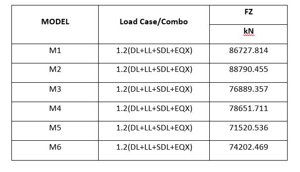
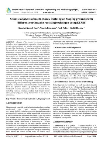
Table 4.2 Base Shear along X direction -zone V (mm)
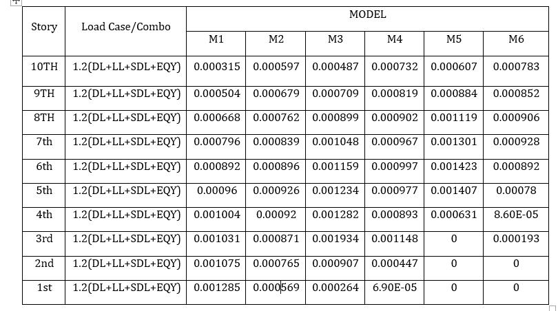
Table no. 4.2 Maximum Story Drift along Y direction zone V (M)
Table no. 5.3 Maximum Displacement along X direction zone V (MM)
5.1 GRAPHICAL REPRESENTATION FOR BASE SHEAR
Thebaseshearinthecolumnsinlongitudinalandtransverse directionisconsideredforanalysisinseismiczoneVshown intableno5.1andgraphicalrepresentationofdataisshown inFigno.5.1.
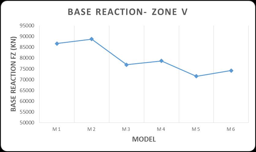
Graph 5.1 Base Shear along X direction -zone V (mm)
5.1Observations:-
1. Plotsofthebaseshearinlongitudinallyaremade forsixmodels,allimposedonthesamegraph.The base shear is directly proportional to weight of structure.
2. From the above graphs base shear profiles it is observedthatminimumshearoccursin30oslope with shear wall and maximum base shear is occurredonbareframebuildingwithnoslope.
5.2 GRAPHICAL REPRESENTATION FOR MAXIMUM DISPLACEMENT
The maximum displacement in the columns in longitudinal and transverse direction is considered for analysisinseismiczoneVshownintableno5.2to5.3and graphicalrepresentationofdataisshowninFigno.5.2.1to 5.2.5
International Research Journal of Engineering and Technology (IRJET) e-ISSN: 2395-0056
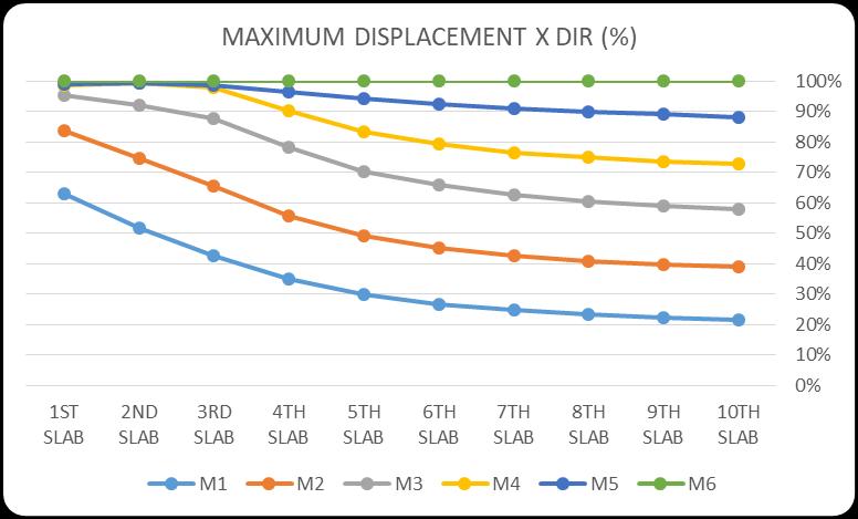
Graph No. 5.2.1. Maximum Displacement along X direction zone V (%)
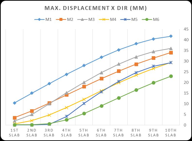
Graph No. 5.2.2. Maximum Displacement along X direction zone V (MM)
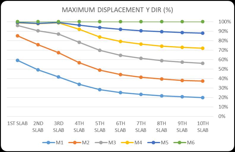
Graph No. 5.2.3 Maximum Displacement along Y direction zone V (%)
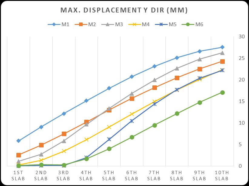
Graph No. 5.2.4 Maximum Displacement along Y direction zone V (MM)
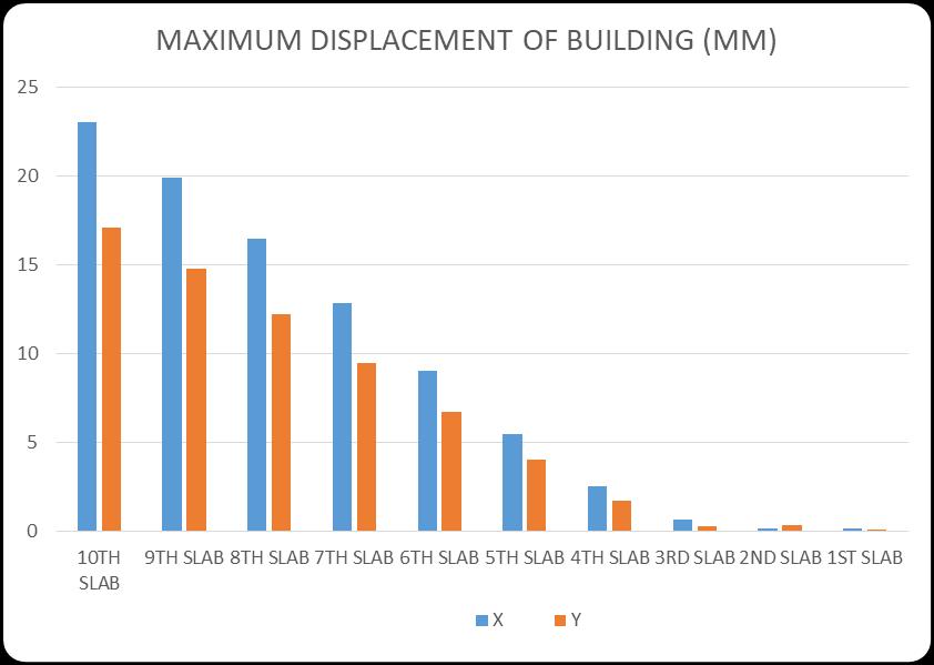
Graph No. 5.2.5 Maximum Displacement comparative 1.2(DL+LL+SDL+EQX) along X & 1.2(DL+LL+SDL+EQY) Y direction zone V (MM)
5.2.1Observations:-
1. Foreasycomparisonofthelateraldisplacementof the selected building, plots of the story level displacementinlongitudinal ortransverseversus heightaremadeforthesixcases,allimposedonthe samegraph.
2. Fromtheabovegraphs displacementprofilesitis observed that maximum displacement occurs in bareframebuildingwithzeroslopebuilding.
3. From the above mentioned graphs it is clearly observedthatmaximumdisplacementisoccurred incase1andminimumdisplacementisobtainedin thebuildingwith30oslopewithshearwall.From thisrepresentationofthegraphsitcanbesaidthat displacement is significantly reduce as slope in increased.
Volume: 11 Issue: 04 | Apr 2024 www.irjet.net p-ISSN: 2395-0072 © 2024, IRJET | Impact Factor value: 8.226 | ISO 9001:2008 Certified Journal | Page2338
International Research Journal of Engineering and Technology (IRJET) e-ISSN: 2395-0056
Volume: 11 Issue: 04 | Apr 2024 www.irjet.net p-ISSN: 2395-0072
4. Fromtheaboveanalysisthereisremarkable80% differenceinfirstandlastreadingstakenongraphs formodel1andmodel5.
5. Shear wall plays significant role in reducing the lateral displacement,provisionofshearwallsina singlebayreducethedisplacementupto20%.
6. In the graph no.5.2.5 displacement is plot for 1.2(DL+LL+SDL+EQX) in x direction and 1.2(DL+LL+SDL+EQY)inYdirection,displacement in X direction is significantly higher as compare withYdirection.
1. Earthquake is happened due to the ground motion intensity of which is mapped by the rector scale, due to such adverse shaking of ground building structure faces a severe damage and to take care of such effects it is important to understand the properties of earthquakeandpredictthepossiblereaction onthebuildingstructure.
2. Story comparing the X direction force for 1.2(DL+LL+SDDL+EQX) and Y direction for 1.2(DL+LL+SDL+EQY) it is clearly seen that displacement in Y direction with EQY forces gives higher displacement it is due the less supportinYdirection.
3. InthecaseofBaseshear,itisconcludedthat valueforthemodel-1(i.e.0oslopewithbare frame)ishigherandgraduallyreduceasslope ofthebuildinggoesonincreasingthoughitis lesserinthecaseof300slopewithshearwall.
1. PrashantD,Dr.JagadishKoriG“SeismicResponseof one way slopeRC frame building with soft storey” International Journal of Emerging Trends in Engineering and Development Issue 3, Vol.5 (September2013).
2. Umakant Arya1, Aslam Hussain2, Waseem Khan3 WindAnalysisofBuildingFramesonSlopingGround Max
3. Narayan Kalsulkar And Satish Rathod “ Seismic analysisofRCCbuildingrestingonslopingground withvaryingnumberofbaysandhillslopes”.IJCET journalvolume5.No.3(june2015)paperNo2063.
4. Anjeet Singh Chauhan, Rajiv Banerjee, “Seismic response of irregular building on sloping ground”. Volume 12, Issue 5, May 2021, pp., International Journal of Advanced Research in Engineering and Technology (IJARET).181-202, Article ID:
IJARET_12_05_017ISSNPrint:0976-6480andISSN Online:0976-6499
5. Pawan Pawar Asst. Prof. Deepa Telang A ComparativeStudyonSeismicAnalysisofMultistory Building Resting on a Sloping Ground and Flat Ground
6. PrasadRameshVaidya,“SeismicAnalysisofBuilding with Shear Wall on Sloping Ground”. International JournalofCivilandStructuralEngineeringResearch ISSN2348-7607(Online)Vol.October2014-March 2015, Volume 2,Issue2, pages53-60, accessibleat www.researchpublish.com
7. D.J.Misal,M.A.Bagade,“StudyofSeismicBehaviorsof Multi-Storied R.C.C. Buildings Resting on Sloping Ground and Considering Bracing System”(IJREST ISSN2395-6453(Online)Vol.2,Issue1(2016)
ISCODES:-
1. IS1893:2002 (Criteriaforearthquakeresistant designofstructurespart1generalprovisionand buildings)
2. IS456:2000(PlainandReinforcedConcreteCodeofPractice)
3. IS13920:1993(Ductiledetailingofreinforced concretestructuressubjectedtoseismicforces codeofpractice)