
International Research Journal of Engineering and Technology (IRJET) e-ISSN: 2395-0056
Volume: 11 Issue: 04 | Apr 2024 www.irjet.net p-ISSN: 2395-0072
International Research Journal of Engineering and Technology (IRJET) e-ISSN: 2395-0056
Volume: 11 Issue: 04 | Apr 2024 www.irjet.net p-ISSN: 2395-0072
Mr. M. Balaji 1 , B. Nithin Kumar 2, N. Tejeswara Rao 3, J. Veera Narayana 4, P. Venkat Charan 5, D. Gowtham6
1 Assistant professor and HOD, Department of Mechanical Engineering, Annamacharya Institute of Technology & Sciences, Tirupati
2 3 4 5 6 Student, Department of Mechanical Engineering, Annamacharya Institute of Technology & Sciences, Tirupati ***
Abstract - Inthis paper,a four-columntype hydraulicpress of one hundred tons is optimized by taking into consideration factors like the structural design of the component and the weight of the component. The work focuses on the optimization of the crown of the hydraulic press. The crown carries a hydraulic cylinder that can generate a load of one hundred tons. The design is based on the optimization of size and the results are validated by using solid-edge stimulation and analysis software by considering proper boundary conditions.
Key Words: SolidEdge,Crown,Structuraldesign,Design optimization,Analysis.
1. Introduction
ThehydraulicpressoperatesontheprincipleofPascal’slaw, theworkofthispressistogeneratecompressiveforceby meansofhydraulics.Theuppermostpartofhydraulicpress isa crownwhichensuresuniformdistributionofreaction load of cylinder and resulting in more accurate and consistentformingofmaterial.
2. Literature Review
D. Ravi et al. (2014) made significant strides in hydraulic presstechnologybyleveragingPRO/ENGINEERandANSYS software to develop and analyze a C-frame power press. Theirapproachsuccessfullyachievedweightreductionwhile ensuring structural integrity, marking a notable advancementinpressdesignoptimization[2] .
N.A.Anjumetal.(2017)contributedtothefieldbydesigning ahydraulicpresstailoredforequalchannelangularpressing. Through experimental validation, they demonstrated the press'sabilitytoperformsatisfactorilyunderaworkingload of 40 tons, showcasing its effectiveness in specialized metalworkingapplications[3]
MohammedIqbalKhatibetal.(2020)introducedamanualoperated 5-ton hydraulic press, emphasizing its userfriendly features such as interchangeable molds and dies without the need for ram assembly disassembly. This innovationenhancesoperationalefficiencyandversatilityin variousmanufacturingprocesses[4]
Akshay Vaishnav et al. (2016) focused on optimizing hydraulic press crown design through Finite Element Analysis (FEA) using ANSYS software. Their rigorous analysisidentifiedthesafestdesignamongmultiplevariants, contributing to enhanced structural robustness and operationalsafetyinhydraulicpressapplications[5]
Inahydraulicpress,thecrownreferstotheuppermostpart ofthepressassembly,whichcarryahydrauliccylinderatthe middleoftheit.Thecrownissupportedbythefourcolumns whicharefixedtothebaseofpress.Ascylinderinworking condition generate the indirect load (reaction force) on crown. This load causes bending and compression in the part.
Table 1: Therequireddimensionsandloadconditions
Constrains Values
Breadth(b)
Height(h)
Width(d)
Workingload
Testingload(w)
1500mm
300mm
750mm
100Ton
150Ton
The crown has been designed from the fundamental calculations. In present work, the design is done to withstandthemaximumdeformationof1mm/m.herethere arethreedifferentDesignofcrownarepresentusingsizing optimization method, with varying internal structural design.
Atworkingcondition,thecrownshouldwithstandtheload of100Ton.Forthisevaluation,thefactorofsafetyistaken as1.5(i.e.,testingload150Ton).Thehydrauliccylinderis mounted on the crown in the middle so, it will carry the amount of the reaction force from the cylinder. There are threeuniquedesignDesignsfromwhichtheoptimumdesign isselected.Forthiswork,SolidEdgestimulationsoftwareis usedfor3Dmodellingandanalysis.
International Research Journal of Engineering and Technology (IRJET) e-ISSN: 2395-0056
Volume: 11 Issue: 04 | Apr 2024 www.irjet.net p-ISSN: 2395-0072
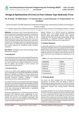
Design 1
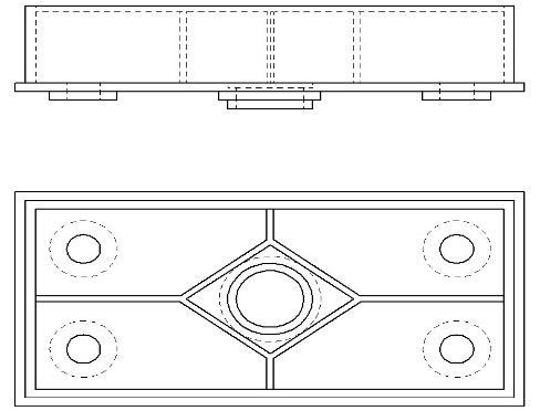
Figure 3a: design1sketch
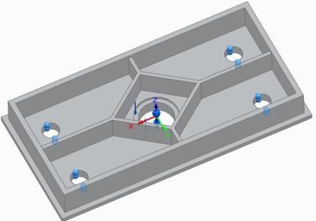
Figure 3b: design1CADmodel Design 2
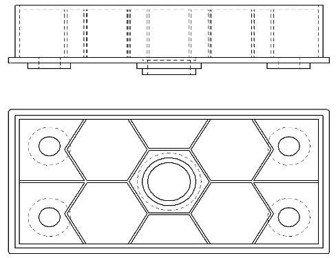
Figure 4a: design2sketch
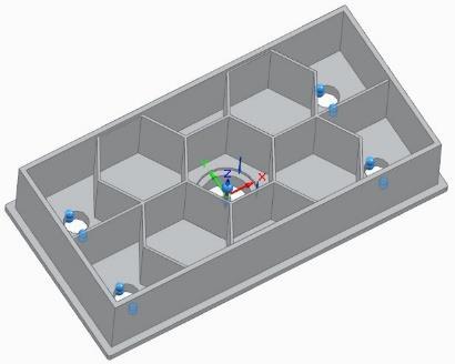
Figure 4b: design1CADmodel Design 3
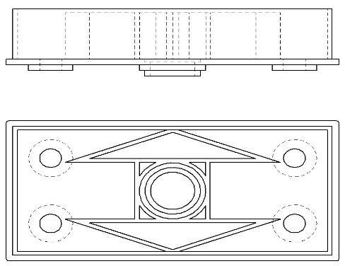
5a: design3sketch
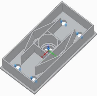
Figure 5b: design1CADmodel
5. Results & Discussion
InthisDesign,a150Tonofloadappliedatthemiddleofthe crown,wherethecylinderisplaced.Alltheremainingholes aretakenasthefixedastheconstrainsbecausethepillars arethesupporttothemachine.ForFEA,SolidEdgesoftware isused.
Therearetwoprimarilyoutputobtainedfromanalysis,total deformationandmaximumvon-misesstress.Basedonthe results,thesuitabledesignisselectedasrequirement.
Table 2: Materialpropertiesusedintheproblem.
Material
Mpa
International Research Journal of Engineering and Technology (IRJET) e-ISSN: 2395-0056
Volume: 11 Issue: 04 | Apr 2024 www.irjet.net p-ISSN: 2395-0072
Design 1
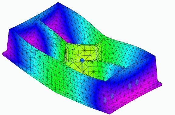
6a: Totaldeformation
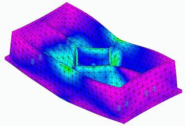
6b: Von-Misesstress Design 2
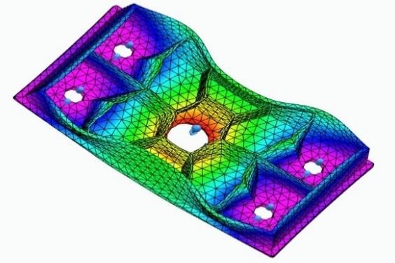
7a: Totaldeformation
7b: Von-Misesstress
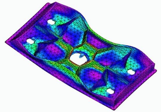
Design 3
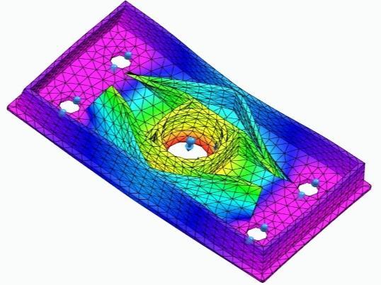
8a: Totaldeformation
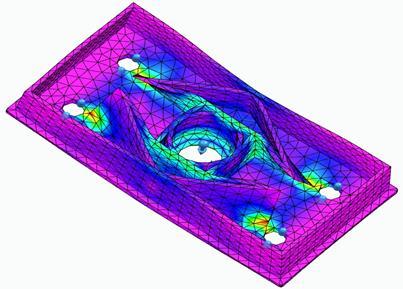
Figure 8b: Von-Misesstress
ThefollowingaretheresultsobtainedfromaboveDesigns at 300 mm of height for all 3 Designs. The results are as follows:-
Table 3: Result
By varying height of crown, the following results are obtainedtoachieveminimumdeformation.
International Research Journal of Engineering and Technology (IRJET) e-ISSN: 2395-0056
Volume: 11 Issue: 04 | Apr 2024 www.irjet.net p-ISSN: 2395-0072
Design 1
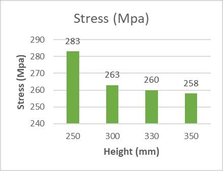
Figure9a: StressVsHeight
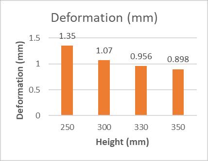
Figure9b: DeformationVsHeight
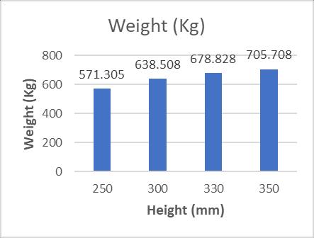
Figure 9c: WeightVsHeight
Figures9a,9b,9cshowtheresultofstress,deformation andweightobtainedwithwhenthereisadimensional change(height)indesign1.
|
Design 2
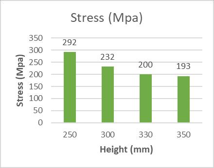
Figure10a: StressVsHeight
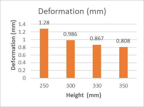
Figure10b: DeformationVsHeight
Figure 10c: WeightVsHeight
Figures10a,10b,10cshowtheresultofstress, deformationandweightobtainedwithwhenthereisa dimensionalchange(height)indesign2.
International Research Journal of Engineering and Technology (IRJET) e-ISSN: 2395-0056
Volume: 11 Issue: 04 | Apr 2024 www.irjet.net p-ISSN: 2395-0072
300mmheight,underFEAtheresultobtainedare underdesiredvalues.
Also, the value of maximum stress is less than the ultimatestressofthematerial.So,thedesignisunder saferconditions.
By comparing the Figures it’s clear that 3rd design has less deformation. But comparing with the weight, the 2nd design has less weight with acceptablerangeofstressanddeformation.
So, from the above result, it is concluded that 2nd designcanbeproposedformanufacturing.
Figure11a: StressVsHeight
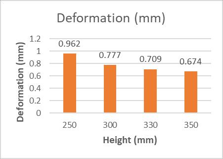
Figure11b: DeformationVsHeight
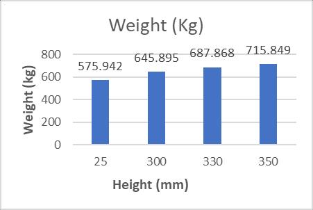
Figure 11c: WeightVsHeight
Figures11a,11b,11cshowtheresultofstress, deformationandweightobtainedwithwhenthereisa dimensionalchange(height)indesign3.
6. Conclusions
Foroptimization,thedesignismodifiedbychanging demissionandstructuraldesign.The2nddesignwith
1. H.M.Naveen,“SolidEdge3dModelofSynthesizedGeared Slider Crank Mechanism with Variable Topology Features”,IJESRCET,ISSN:2456-3307,May–June3021
2. D.Ravi,“ComputerAidedDesignandAnalysisofPower Press”, Middle East journal of Scientific Research 20(10):1239-1246,2014.
3. N.A.Anjum,“Design,FabricationandManufacturingof 100 Ton Hydraulic Press to Perform Equal Channel Angular Pressing”, Technical Journal, University of EngineeringandTechnology(UET)Taxila,PakistanVol.22 No.11-2017.
4. MohammedIqbalKhatib,“DesignandFabricationof5 TonHydraulicPressMachine”,InternationalJournalof ScientificResearchinScience,Engineering&Technology, Vol.7Issue2,March-April2020Pg:22-30.
5. Akshay Vaishnav, “Design Optimization of Hydraulic PressPlateUsingFiniteElementAnalysis”,International JournalofEngineeringResearchandApplications,Vol.6 Issue5,May2016,PgNo.58-66.