
International Research Journal of Engineering and Technology (IRJET) e-ISSN: 2395-0056
Volume: 11 Issue: 04 | Apr 2024 www.irjet.net p-ISSN: 2395-0072
International Research Journal of Engineering and Technology (IRJET) e-ISSN: 2395-0056
Volume: 11 Issue: 04 | Apr 2024 www.irjet.net p-ISSN: 2395-0072
Vishrut Jaiswal1 , Siddhesh Kadam2 , Pratik Koli3 , Harsh Patil4
1,2,3,4 Students, Dept. of Mechanical Engineering, Bharati Vidyapeeth College of Engineering, Navi Mumbai, India
Abstract - Ensuring the stability of a two-wheeledvehicleis crucial in the modern transportation system. Gyroscopes are key in helping stabilize these vehicles. There is a belief that vehicles stabilized by gyroscopes would be safer than traditional two-wheelers.Toachievethisdynamicstability,the torque on the vehicle must be counteracted by the torque generated by the gyroscope within the vehicle. In thiscase,the gyroscope acts as an actuator rather than a sensor, utilizing precession forces. When force is applied to a direction perpendicular to the rotation axis of a gyroscope, making it spin around, a force is created around a third axis, which is at right angles to both the force and rotation axes. As the vehicle leans away from the upright position, a force that induces precession is applied to the gyroscope unit and the counteracting gyroscopic reaction force will move to stabilize the vehicle. The main concept is that the movement of the gyroscope about the body is purposely managed to produce a stabilizing force. Our team created a self-balancing twowheeler using an inverted pendulum principle. The project involved designing the model in software, fabricating it, assembling it, and conducting thorough testing.
Key Words: Stability, Two-wheeled vehicle, Gyroscopes, Torque, Inverted pendulum
Therearemanydifferenttypesoftwo-wheeledvehicleswith parallel spin axis, commonly used for transportation or recreation. Lighter vehicles with smaller engines are generallymoreaffordablecomparedtoheaviermodelsand are a popular choice for transportation in many Asian countries.Unfortunately,alargenumberofroadaccidents involve these types of vehicles. Despite significant investments in manufacturing and developing advanced technologyformotorbikes,roadsafetyultimatelyrelieson theskillsandjudgmentoftherider.Accidentsoftenoccur when the rider loses control of the bike and falls. Additionally, children learning to ride bicycles may be hesitantduetoafearoffalling.
The device operates using an inverted pendulum concept andutilizeselectromechanicalpartstofunctionasapersonal vehicle. It is a two-wheeled, self-balancing mode of transportation that is complex and inherently unstable. Managingthistypeofsystemisachallengingtask,leadingto ongoingresearch.[8]
Thispapershowcasesavehiclewhereallparts(mechanical, electrical)arecustom-designed,manufactured,assembled, andtested.Thisvehicleisenvironmentallyfriendly,runson batteries,andisuser-friendly.
The problem with a traditional bike is that it requires the ridertomaintainbalancethroughconstantadjustmentsof bodypositionandsteering.Hence,weneedtodevelopaselfbalancingbikethatshouldbeabletomaintainbalancewhen subjectedtoexternaldisturbances,suchaswind,andshould alsobeabletorespondquicklytoriderinput,suchassteering andacceleration.Theprojectwillneedtoaddressseveralkey challengesincludingadjustingthemotortorqueinreal-time, and the design of a lightweight and durable mechanical structure.
Motorcycles are a widely used form of transportation across the world due to their energy efficiency, compact design, convenience, and stylish appearance. Many young people see them as a trendy way to get around, while in developingcountries,theyareoftenusedasaffordable,fuelefficient vehicles. However, despite their popularity, motorcycles lack safety features and are considered highriskvehicles.Thisleadstofatalaccidents,withinjuriesbeing common and death a frequent outcome. One major safety issue with motorcycles is that the passenger's body is exposedduringtheride,makingthemvulnerabletoimpacts withroadsideobjects.
Definetheprojectrequirements:Determinethepurpose, target audience, and specific requirements of the selfbalancingbikeproject.
Research the state of the art: Explore the latest technologies, components, and materials used in selfbalancing bikes, as well as their strengths and weaknesses.
Design the self-balancing system: Develop a selfbalancingcontrolalgorithmthatcanmaintainthebike's balanceusingsensorsandactuators.
International Research Journal of Engineering and Technology (IRJET) e-ISSN: 2395-0056
Volume: 11 Issue: 04 | Apr 2024 www.irjet.net p-ISSN: 2395-0072
Select the appropriate components: Select the componentsrequiredfortheself-balancingsystem,such as motors, batteries, sensors, and microcontrollers, basedontheircompatibility,reliability,andcost.
Assemblethebikeframe:Designandassemblethebike frame with lightweight and durable materials, considering the bike's balance, ergonomics, and aesthetics.
Integrate the self-balancing system: Integrate the selfbalancingsystemwiththebikeframe,ensuringproper alignment,calibration,andsynchronization.
Testandvalidatethesystem:Testtheself-balancingbike invariousenvironmentsandconditions,validatingthe system'sstability,agility,andsafety.
Optimize the system performance: Fine-tune the selfbalancing algorithm, adjust the components, and optimizethebike'sperformanceandefficiency.
Showcase the project: Demonstrate the self-balancing bikeprojecttothetargetaudience,sharingitsfeatures, benefits, and innovation, and inviting feedback and suggestionsforimprovement.
2.1 Construction
This paper aims to demonstrate that a body can stay balancedontwoparallelspinningwheels,whetheridleorin motion,byutilizingamechanicalgyroscope.Thisgyroscopic principlecanbeappliedeffectivelyindesigningaprototype of a two-wheeled vehicle to study the gyroscopic phenomenon.
The prototype was assembled with the following components:
1. SteelFrame
2. WoodenBase
3. 12VDCMotor
4. MotorDriver
5. Regulator
6. Mildsteeldisc
7. RubberWheels
8. Nutsandbolts
9. Hub
10. Ballbearings
ThegyroscopedisciscreatedusingaCNClatheanddrilling techniques.Thesteelframeworkisattachedtothebottom steel base. Circular edge wheels are placed on the bottom steel base, and holes are drilled in the framework to accommodate the gyroscope assembly's gimbal. The DC motor is mounted on a U bracket on the gimbal. The key requirementforthissetupisforthemassdistributiontobe top-heavy, with the majority of the mass located on the uppersideofthegimbal.Thecenterofgravityistherefore just above the gimbal axis, and stainless steel discs are mountedonthemotorshafttoactasthegyroscope.TheDC motor issecurelyattachedtothe U-bracket, allowingit to stay in place. The shaft of the DC motor is connected to a steelhubwithholesdrilledonthetopsurface.Thishubis used to mount the gyroscope disc by bolting it on. The materialsusedforthegyroscopedisc,hub,steelframe,and U-bracketareMild Steel. To complete theassemblyofthe model, nuts and boltsofvarioussizeswereused.Onekey design consideration we made in this model is that the gyroscopediscshouldbeabletofreelymovewithintheUbracket attached to the steel frame. To achieve this, we utilized ball bearings and studs to facilitate smooth and flexible angular movements and adjustments. The circlips were employed on the inner ends of the studs to prevent themfromdislodgingfromtheball bearings,ensuringthe modelremainedintactduringoperation.Thedesignallows the front wheel to pivot and change direction to navigate turnseffectively.
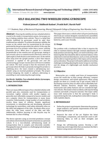
The machine runs on a 12V power source. When the motor beginstospin,a mildsteel disc attachedto the motorshaftstartsturningandpicksupspeedslowly.
Whenthediscrotates,itcreatesagyroscopiceffectthat helps stabilize the prototype model by counteracting any imbalance in the wheels. This effect happens on boththeleftandrightsidesofthemodel
Therefore, the gyroscope's rotation creates a reactive gyroscopicforcethatstabilizestheprototype.Themotor
International Research Journal of Engineering and Technology (IRJET) e-ISSN: 2395-0056
Volume: 11 Issue: 04 | Apr 2024 www.irjet.net p-ISSN: 2395-0072
and gimble axle are intentionally made heavy to maintainstability.
The center of gravity is positioned above the gimbal axle,causingthemotorandgyroscopeassemblytowork towardsadownwardmovementofthecore'scenterof gravity.Simultaneously,themotorandgimbalassembly are set up within the frame with bearing reactions at bothends.
So,theonlypossiblewayforthemotortoattainstability is to either lean forward or backward. So, when the motorisstartedthebodyisabouttofalloneitherside and the motor assembly is leaning this causes the precessionofthespinaxis.
As the gyroscope precesses, the reactive gyroscopic couple follows the right-hand rule and stabilizes the vehiclebycounteractingthedisturbingcouple.Through multiplerotationsandoscillations,themotorandframe eventually reach a stationary position, allowing the gyroscopetosmoothlyrollaboutitsspinaxis.
Basicformulasusedincalculations:
Centreofmassfromground(h):
CentreofMass(CM)fromtheground,h= [(CMwheel*Mwheel)+(CMchassis*Mchassis)+(CMframe *Mframe)+(CMdisc*Mdisc)+(CMhub motor * Mhub motor) + (CMlinkage * Mlinkage)] / Total Mass.
MomentofInertia,I=mr²/2
SpeedofDisc(N)=RPM
PrecessionspeedofDisc(ωp):ωp=m.g.h.sinθ/Iω
GyroscopicreactionTorque(τ):τ=Iωωp m=Massofthedisc=0.8012kg r=Radiusofthedisc=140cm
1 5
3 15
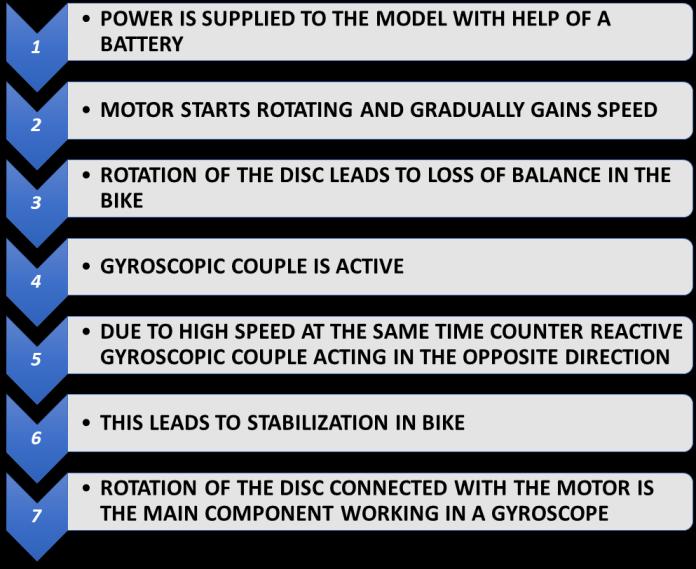
RelationshipbetweenTiltAngleandRPM: -Astheangleof tiltincreases,thespeedinRPMalsoincreases.Thisindicates thatthegyroscope'sresponsetomaintainbalanceismore aggressive(faster)asthetiltanglebecomeslarger.
Specific Observations: - Between5°and10°tilt,theRPM increasesby26RPM. -From10°to15°,theincreaseis52 RPM. -From15°to20°,theRPMincreasesby68RPM. -
From20°to25°,theincreaseis92RPM. -From25°to30°, the RPM increases dramatically by 356 RPM. This sharp increase may indicate that the system is designed to react moreurgentlyastheriskoffallingincreases(i.e.,athighertilt angles).
ImplicationsforStabilityControl: -Thedatalikelyreflectsa controlstrategywherethegyroscopicsystemappliesmore force (via higher RPM) to counteract greater angles of tilt. Thestrategymightbefine-tunedtopreventovercorrectionat lowertiltanglesbutbecomessignificantlymoreaggressive whenthebikereachesacriticaltiltangle,asevidencedbythe sharpRPMincreaseat25°to30°.
Thisanalysisindicatesthatthegyroscope'sfunctionalityand itsintegrationintothebike'scontrolsystemarecrucialfor ensuringstability.
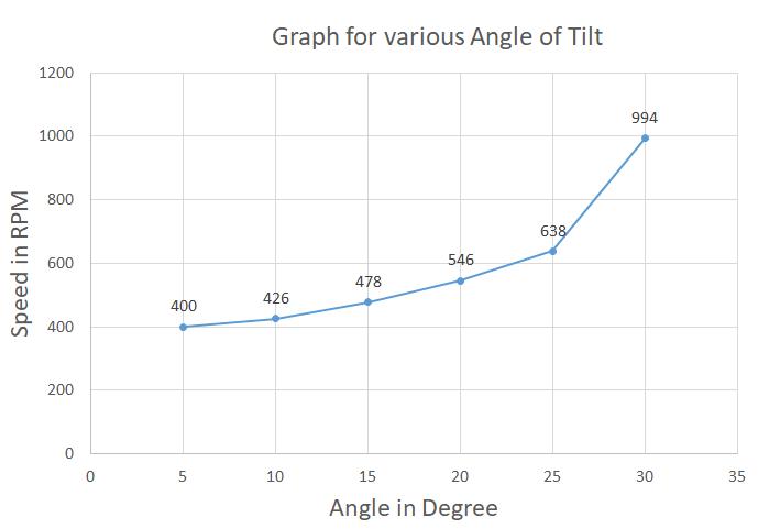
Chart -1:RelationbetweenRPMandAngleofTilttillthe vehicleisunbalanced.
To sum up, a self-balancing bike project could change the wayweviewandusebikesforgettingaround,havingfun, andgettinghelpwithmobility.Thetechnologybehindselfbalancingbikesenhancestheirstabilityandeaseofhandling, makingthemsaferandmoreaccessibleforridersofallages andabilities.These bikesrequirelessphysical exertion to ride, are low-maintenance, and are eco-friendly, making themagreatchoicefortransportation.
Whendesigningandputtingintoactionaself-balancingbike, it'scrucialtotakeintoaccountfactorssuchascost,weight, powersourceneeds,environmentalconsiderations,andthe learningcurveinvolvedwiththetechnology.Theprojectof engineering a self-balancing bike presents a range of advantages and obstacles that need to be carefully considered to assess its potential success in different marketsandapplications.
International Research Journal of Engineering and Technology (IRJET) e-ISSN: 2395-0056
Volume: 11 Issue: 04 | Apr 2024 www.irjet.net p-ISSN: 2395-0072
FinalModelImages:

ACKNOWLEDGEMENT
We are thankful to “Bharati Vidyapeeth College of Engineering,”forconsideringourProject andconsideringus through the various stages of the project. It gives us immensepleasuretoexpressoursinceregratitudetowards ourProjectguideandCo-ordinatorProf.V.N.PATILforhis guidanceinselectingthefinalyearprojectandforproviding uswithallthedetails.
We are deeply indebted to our respected Principal, Dr. Sandhya Jadhav, and HOD, Dr. S.N.Teli for giving us this valuableopportunitytodothisprojectandweexpressour heartilythankstothemfortheirassistancewithoutwhichit wouldhavebeendifficulttofinishthisfinalyearprojectand researchpapersuccessfully.
Weconveyourdeepsenseofgratitudetoallteachingand non-teaching staff of the Mechanical Department for their constant encouragement, support, and timely help throughout the final year of project work and research paper.
[1] Ching-Chih Tsai, Hsu-Chih Huang, and Shui-Chun Lin, “Adaptive Neural Network Control of a SelfBalancing Two-Wheeled Scooter,” IEEE TransactionsonIndustrialElectronics,vol.57,no.4, April2010
[2] Karthik,Ashraf,AsifMustafaBaig,andAkshayRao, “Self-BalancingPersonalTransporter”4thStudent ConferenceonResearchandDevelopment,pp.180183,June.2006
[3] Pawel Bethke,Rafal DlugoszandTomaszTalaska, “Project and realization of two wheels balancing vehicle,” 20th International Conference "Mixed DesignofIntegratedCircuitsandSystems",June2022,2013,Gdynia,Poland.
[4] StephenC.SpryandAnouckR.Girard,“Gyroscopic Stabilization of Unstable Vehicles: Configurations, Dynamics,andControl”March31,2008
[5] Kealeboga Mokonopi, “BALANCING A TWO WHEELED ROBOT,” University of Southern QueenslandFacultyofEngineeringandSurveying BachelorofEngineeringandBachelorofBusiness (Mechatronics and Operations Management) Submitted:November2006
[6] “ADynamicModelforSelf-BalancingTwo-Wheeled Electric Vehicles" by J. Zuo, L. Sun, and J. Liu, publishedintheInternationalJournalofElectrical PowerandEnergySystems,2018
[7] AkshayKhot,NishadKumbhojkar,“MODELINGAND VALIDATIONOFPROTOTYPEOFSELFSTABILIZING TWO-WHEELERUSINGGYROSCOPE”,Department of Mechanical Engineering, Sinhgad College of Engineering,Pune,Maharashtra,India
[8] Pratik D. Tak 2017 'Self-Stabilizing Bike Using Gyroscope'IJRET:InternationalJournalofResearch inEngineeringandTechnology,Volume:06Issue: 11.
[9] NitheeshKumarG,NavneethS,SurajA,andPramod Sreedharan,“DesignandAnalysisofaSelf-balancing Bicycle Model” International Conference on Innovations in Mechanical Sciences (ICIMS\'21)2021
International Research Journal of Engineering and Technology (IRJET) e-ISSN: 2395-0056
Volume: 11 Issue: 04 | Apr 2024 www.irjet.net p-ISSN: 2395-0072

“Mr. Vishrut Jaiswal”, Student, Dept. of Mechanical Engineering, Bharati Vidyapeeth College of Engineering,NaviMumbai,India
“Mr. Siddhesh Kadam”, Student, Dept. of Mechanical Engineering, Bharati Vidyapeeth College of Engineering,NaviMumbai,India
“Mr.PratikKoli”,Student,Dept.of Mechanical Engineering, Bharati VidyapeethCollegeofEngineering, NaviMumbai,India
“Mr.HarshPatil”,Student,Dept.of Mechanical Engineering, Bharati VidyapeethCollegeofEngineering, NaviMumbai,India