
International Research Journal of Engineering and Technology (IRJET) e-ISSN: 2395-0056
Volume: 11 Issue: 04 | Apr 2024 www.irjet.net p-ISSN: 2395-0072
Air Core Generator
Ms. Sneha Baliram Tambe1 , Mr. Gopal Chaudhari 2
Ms. Sneha Baliram Tambe, Dept. of Electrical Engineering, YTIET ,Karjat, Maharashtra, India. Mr. Gopal Chaudhari, Dept. of Electrical Engineering, YTIET , Karjat, Maharashtra, India.
Abstract – Due toenvironmentalconcerns arisingfrom the frequent overuse of resources, attention has now shifted to non-renewable sources, especiallysolar andwindas theseare environmentally cleaner and not environmentally friendly. Modern technologies incorporated in wind turbines have increased the limits of wind power generation to a greater extent in wind turbines. Thus, wind energy penetration has become increasingly important and requires robust, sophisticated and reliable networks.
This paper presents the design and construction of a permanent magnet machine with an air core stator.
KeyWords: Air-coredstator,PMmachines,RadialFlux Permanent Magnet (RFPM), neodymium magnet. Faraday’s law of electromagnetic induction.
1. INTRODUCTION
GENERATION OF ELECTRICITY: -
In1831-1832MichaelFaradaydiscoveredthatapotential difference is produced between the ends of an electrical conductorwhichmovesperpendiculartoa magneticfield The first electromagnetic generator based on this effect, using a copper disc rotating between the poles of a horseshoemagnetwhichproducesasmalldirectcurrent.It is based on the principle that when a current carrying conductor coil or conductor is rotated in the permanent magnetic field, the e.m.f. is generated However, due to the low power intensity, we provide a low voltage that can be increased if larger drives are used.
1. ALTERNATOR
1.1 An Alternator: An alternator is a generator that converts mechanical energy into electricity to produce alternatingcurrent.IntheoryanyACgeneratorcanbecalled analternator,butthetermgenerallyreferstosmallrotating machines powered by internal combustion engines and otherautomotive.
1.2 Theory of operation
AlternatorsproduceelectricityonthesameprincipleasDC generators.Whenmagneticfieldlinescrossaconductor,a currentisinducedintheconductor.Analternatorgenerally hasastationary(stator)anda rotating(rotor).Thestator hasawindingofconductorsandarottingmagneticfieldin
therotor.Thefieldcutsacrosstheconductorsandgenerates electricity, while the mechanical input causes the rotor to rotate. The rotor magnetic field can be generated by induction(in"brushless"generators),permanentmagnets, or rotor windings with direct current through slip ring brushesautomotivealternatorsusesbrushesandsliprings. Which is used to regulate the voltage produced by the alternatorbyvaryingthecurrentintherotorfieldwindings. Permanentmagnetdevicesavoidlossesduetomagnetizing currentintherotorbutarerestrictedinsizeduetodueto thecostofthemagnetmaterial.BrushlessACgeneratorsare generally larger devices than those used in automotive applications.
1.3 Automotive alternators
1.3.1Alternatorsareusedinvehiclestochargebatteriesand power all electrical systems when the vehicle engine is running. A major advantage of alternators over directcurrent generators is that they do not use commuters, making them simpler, lighter and more robust than DC generators. The stronger construction of the alternator to turnathigherspeed,allowingtheautomotivealternatorto turnattwicetheenginespeed,improvewhentheengineis idling.Sinceabout1960,theavailabilityofinexpensivesolidstatediodeshasenabledautomakerstoreplacegenerators with alternators. Automotive alternators use a set of rectifiers(diodebridges)toconvertACtoDC.Automotive alternatorshavethree-phasewindingswhichprovidedirect currentwithalowripple
1.3.2 Very large automotive alternators used in heavy equipmentoremergencyvehiclesarecapableofdelivering 150 amps. Old automobiles with minimal lighting and electronics may only have a 30 amp alternator. Hybrid automobiles use a motor/generator combination that replacestheseparatealternatorandstartermotor,running theinternal combustion engine duringstart-up,providing additionalmechanicalenergyforacceleration,bouncelarge batterystoragewhendrivingatconstantspeeds.Arotating magneticfieldisamagneticfieldthatperiodicallychanges direction. Thisisthebasicprincipleofalternatingcurrent motors.
International Research Journal of Engineering and Technology (IRJET) e-ISSN: 2395-0056
Volume: 11 Issue: 04 | Apr 2024 www.irjet.net p-ISSN: 2395-0072

Fig 1: Sinewavecurrentineachofthecoilsproducessine varyingmagneticfieldontherotationaxis.Magneticfields addasvectors.

Fig 2:Vectorsumofthemagneticfieldvectorsofthe statorcoilsproducesasinglerotatingvectorofresulting rotatingmagneticfield.
Arotatingsymmetricmagneticfieldcanbecreatedwithjust afewthreecoils.Thesymmetrical3-phaseACsine-current systemmustincludethreecoils,soeachphasewillbeshifted 120degreestotheothers.Forthepurposesofthisexample, themagneticfieldisassumedtobealinearfunctionofthe current in the coil. Adding three 120-degree phased sine wavestotheaxisofthemotorisasinglerotatingvector.A rotor(withaconstantmagneticfielddrivenbyaDCcurrent oraconstantmagnet)attemptstoadoptapositionsuchthat the N pole of the rotor adjusts the S pole of the stator magnetic field, and vice versa. This magneto-mechanical forcewilldriverotortofollowrotatingmagneticfieldina synchronousmanner. Insuchafield,apermanentmagnet willrotatesoastomaintainitsalignmentwiththeexternal field. This effect was applied in early alternating current electricmotors.Twoorthogonalcoilswithaphasedifference of 90 degrees in AC currents can be used to generate a rotatingmagneticfield.Inpractice,however,suchasystem wouldbeprovidedbyathree-wiresystemwithnon-uniform flow. This inequality will cause serious problems in standardizingthesizeoftheconductorandisovercomeby usingathreephasesystemwherethreecurrentsareequalin magnitudeandhaveaphasedifferenceof120degreesthree identical coils whose mutual geometric angles are 120 degreeswillgivearotatingmagneticfieldinthiscase.The abilityofthethreephasesystemtoproducearotatingfield applied in electric motors is one of the main reasons why three phase systems are dominated in the world electric powersupplysystems.Becausemagnetsdegradewithtime, synchronous motors and induction motors use shortcircuited rotors (instead of a magnet) following rotating magneticfieldofmulticoiledstator.(Shortcircuitedturnsof
rotordevelopeddycurrentsinrotatingfieldofstatorwhich (currents)inturnmovetherotorbyLorentzforce).Notethat the rotating magnetic field can actually be produced by two coils, with phases shifted about 90 degrees, but such field would not be symmetric due to difference between magnetic susceptibility of ferromagnetic materials of pole and air. In case two phases of sine current are only available, four poles are commonly used.
1.4 Marine alternators
1.4.1 Marine alternators as used in boats are usually automotive alternators, adapted to the saltwater environment.Theycanbe12or24voltsdependingonthe typeofsysteminstalled.Largermarinefuelsmayhavetwo ormoretransformerstomeetthehighpowerrequirements of a modern boat. In a single alternator circuit, power is divided between the engines starting battery and the household battery (or batteries) by split charge diodes or mechanical switches because the alternator powers only then when driven engine control panels usually provide directly from the alternator via auxiliary terminals. Other specificconnectionsaremadeforchargecontrolcircuits.
1.5 Brushless Alternators
1.5.1
Terminology
Thestationarypartofthemotororalternatoriscalledthe stator and the rotating part is called the rotor. The wires usedtogeneratethemagneticfieldarecalledfields,andthe coilsthatgenerateenergyarecalledarmatures.Thefieldand armaturewiresaresometimescalled“windings”.
1.5.2 Construction
Abrushlessalternatorconsistsoftwoalternatorsbuiltendto-endonthesameshaft.Smallerbrushlessalternatorslook like one unit but in larger ones, the two parts are easily identifiable. The larger of the two parts is the main alternatorandthesmallerexciter.Theexciterhasstationary fieldcoilsandarotatingarmature(powercoils).Themain alternatorusesareverseconfigurationwitharotatingfield andastationaryarmature.
1.6 Exciter
Theexcitedfieldcoilsareonthestatoranditsarmatureison the rotor. The AC output from the exciter armature is suppliedbyaseriesofdiodeswhicharealsomountedonthe rotortoprovideaDCvoltage.Thisgoesdirectlytothefield coilsofthemainalternator,whichisalsoontherotor.With thisarrangementbrushesandslipringsarenotrequiredto flow current through the rotating field coils. This can be comparedtoasimplecaralternatorwherebrushsliprings areusedtoflowcurrenttotherotatingfield.
International Research Journal of Engineering and Technology (IRJET) e-ISSN: 2395-0056
Volume: 11 Issue: 04 | Apr 2024 www.irjet.net p-ISSN: 2395-0072
1.7 Main Alternator
Themainalternatorhasarotatingfieldasdescribedabove and a stationary armature (Power generating winding). If thearmatureisstable,highcurrentshouldnotpassthrough the brush and slip rings. Although the electrical system is more complex, it makes for a very reliable alternator becausetheonlypartsthatcanfailarethebearings.
1.8 Control System
Thestrengthofthemagneticfieldintheexciteriscontrolled by varying the amount of current flowing through the stationaryexcitedfieldcoils.Thisalsocontrolstheexciter output.Theexciteroutputisinjectedwitharotatingfieldfor whichthe mainalternatorgeneratesa magneticfield.The strengthofthealternator’smagneticfieldinthemainthen controls the output. The result of all this is that a small current,controlsthemainalternatoroutputindirectlyatthe locationoftheexciteranddoesnothavetogothroughany brushsliprings
1.9 AVR
AVRisanabbreviationforAutomaticVoltageRegulator.An AVRservesthesamefunctionasthe“voltageregulator”inan automobile or the “regulator” or “controller” in a home powersystem.
1.10 Hybrid automobiles
Hybrid automobiles replace the separate alternator and starter motor with a combined motor/generator that performsbothfunctions,crankingtheinternalcombustion engine when starting, providing additional mechanical powerforaccelerating,andchargingalargestoragebattery when the vehicle is running at constant speed. These rotating machines have considerably more powerful electronic devices for their control than the simple automotivealternatordescribedabove.
1.11 Radio alternators
With the expansion of Tesla's work on high-frequency alternators, high-frequency alternators of the variable reluctance type have been used commercially for radio transmissiononlow-frequencyradiobands.
1.12 Dynamo
2.13.1Thedynamowasthefirstelectricgeneratorcapableof powering industry, and remains the most important electricalgeneratorusedinthe21stcentury.Thedynamo uses the principle of electricity to convert rotating machineryintoalternatingcurrent.
1.13 Gramme dynamo
Butbothofthesesystemshadthesameproblem:theygavea "spike" of current that neither followed at all. The Italian scientist Antonio Pacinotti remedied this by replacing the spinning wires with a toroidal coil, using metal rings to fastenthem.Thismeansthatpartofthecoilwasinmotion withthemagnets,smoothingthecurrentflow.
2. Concepts
It is important to understand that a generator generates electricity, but not electricity, which is already in the conductors of its windings similar to a water pump that makeswaterflowbutnotthewateritself.Thereareother types of electrical generators, based on other electrical properties such as piezoelectricity and magnetic hydrodynamics.Thedesignofadynamoissimilartothatof anelectricmotor,allofwhichcanoperateasconventional dynamo motors. Furthermore, all conventional electric motors could act as generators. The generator rotor is turnedbyadevicecalledaprimemover,usuallyagasoline engine, steam turbine, water turbine or gas turbine connectedtotherotor-shaft.
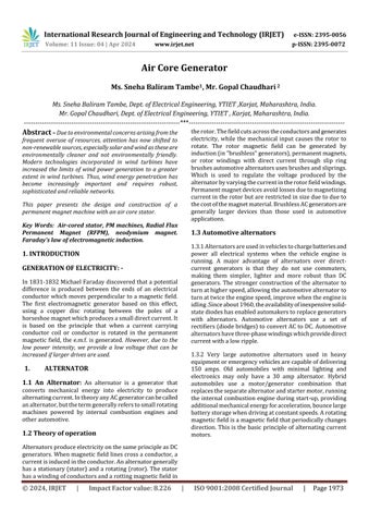
Equivalent circuit
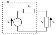
Fig 3:Equivalentcircuitofgeneratorandload.
G=generator
VG=generator open-circuit voltage
RG=generator internal resistance
VL=generator on-load voltage
RL=loadresistance
2.1Theequivalentcircuitofageneratorandloadisshownin the diagram. To determine the generator's VG and RG parameters,followthisprocedure:
Before starting the generator, measure the resistance across itsterminalsusinganohmmeter.ThisisitsDC internalresistance RGDC.
Start the generator. Before connecting the load RL, measure the voltage across the generator's terminals. Thisistheopen-circuitvoltage VG
International Research Journal of Engineering and Technology (IRJET) e-ISSN: 2395-0056
Volume: 11 Issue: 04 | Apr 2024 www.irjet.net p-ISSN: 2395-0072
Connecttheloadasshowninthediagram,andmeasure thevoltageacrossitwiththegeneratorrunning.Thisis theon-loadvoltage VL
Measure the load resistance RL, if you don't already knowit.
Calculate the generator's AC internal resistance RGAC fromthefollowingformula:

Note 1: The AC internal voltage of a generator when it is running isusuallyslightlyhigher thanitsDC resistance at idle.Theprocedureaboveallowsyoutomeasuretwovalues. For more complex calculations, you can skip the RGAC measurementandassumethatRGACisequaltoRGDC.
Note2:IfthegeneratorisanACtype(notadynamo),usean ACvoltmeterforthevoltagemeasurements.
3. CONSTRUCTION DIAGRAM
3.1Metallurgyisfundamentalandyetitoverflowsintoareas of knowledge and remains closed to the general reader. Knowledge of materials and their properties is very
importantforthedesigner.Mechanicalcomponentsmustbe amaterialwithpropertiessuitableforoperatingconditions. In addition to this, the designer must be familiar with manufacturingprocesses,materialpropertiesandoperating temperatures. In designing the parts of a machine, he determines how the material will perform in service. For some of those properties or mechanical properties commonlyusedinindustrialapplications,theyareusually derivedfromstandardtensiletests.Inengineeringpractice, themachinepartsaresubjectedtovariousforces,whichmay beduetoeitheroneormoreofthefollowing.
1. Energytransmitted.
2. Weightofmachine
3. Frictionalresistance
4. Inertiaofreciprocatingparts
5. Changeoftemperature
6. Lackofbalanceofmovingparts
3.2Theselectionofmaterialsdependsonthestressesduring operation.Theselectedmaterialwillendure.Anotherfactor insteelselectiondependsonthetypeofloadtobeapplied because the mechanical component resists machine parts loadsmorethanliveloadsandliveloadsmoreelasticthan shockloads.
4. RAW MATERIAL & STANDARD MATERIAL
Table -1: Rawmaterial
5. COST ESTIMATION
5.1 The cost estimation can be defined as a method of forecasting the costs that must be incurred to produce a
International Research Journal of Engineering and Technology (IRJET) e-ISSN: 2395-0056
Volume: 11 Issue: 04 | Apr 2024 www.irjet.net p-ISSN: 2395-0072
product. These costs consider all costs associated with design and manufacture including all related service activitiessuchassampling,equipment,manufacturinganda portionofalladministrativeandsellingcosts
6.BASICALLY THE BUDGET ESTIMATIONIS OF TWO TYPES:
1. material cost
2. Machiningcost
6.1 MATERIAL COST ESTIMATION:
Materialcostestimationgivesthetotalamountrequiredto collect the raw material which has to be processed or fabricatedtodesiresizeandfunctioningofthecomponents. Thesematerialsaredividedintotwocategories:Materialfor fabrication: Materials obtained in this raw state are processed or processed to a finished size for product efficiency
1. Standardpurchasedparts: This includes the parts which was readily available in the market like allen screws etc. A list is forecast by the estimationstatingthequality,sizeandstandardparts,the weight ofrawmaterial andcostperkg.Forthefabricated parts.
6.2 MACHINING COST ESTIMATION:
Thiscostestimateisanattempttodeterminethetotalcosts thatmaybeincludedinproductioninadditiontomaterial costs.Thecostofmanufacturedpartscanbeconsideredasa decision period after careful consideration including the labor,materialsandfactoryservicesrequiredtoproducethe requiredpart.
7. DESIGN CALCULATION
7.1 Design concept of generator :For the concept of generatordesignisfollowingtothesesteps:
7.1.1 Coil turns calculation
Thissectionisdeterminednumberofcoilturnsforarmature winding.


WhenNisgeneratorspeed(rpm),fisgeneratorfrequency (Hz)andPisnumbersofpole(poles),Bmaxisthemaximum
magnetic density in air gap per pole (Wb/m²), Br is the magneticdensityperpole(Wb/m²), maxisthemaximum flux in air gap (Wb), Lm is the thickness of permanent magnet(m.), istheairgapbetweenstatorandrotor (m.),Amagnetisthecrosssectionalareaofpole(m²)thatcan findbyusingtheproductofwidthandlengthofpermanent magnet, EA is induced voltage (V) or requirement voltagefromgenerator,NCiscoilturns(turns).
Name Symbol Design
OutputVoltage Ea
Roof Ventilator averageSpeed N 30rpm
Poles P 6poles
Airgap 3mm.
Permanent Magnet size W×L×T (10x15x5)mm.
Permanent Magnet Magneticdensity Br 0.05 Wb/m2
Turnspercoil Nc 223turns
Table3:showsthegeneratorparametersforcalculation
7.1.2 Coil span calculation


Thissectionisdeterminedthecoilspanforallinstallation windingonstatorcore. (11) (12) (13)

WhenCoilSpanistherangebetweenfirstcoil-sideandend coil-sidethatcountfromfirstcoil-sideinfirstslottotheend coil-sideintheotherslot(unitmeasurementmaybeuseslot ordegree),Coilgroupisnumberofsubcoilthatdistributed incoilspanofabigcoil,TotalSlotistotalnumbersofsloton statorcore(slots),PoleorPismagneticpole(poles),Phase is number of phase system, is slot angle in each slot, (electricaldegree),Angleistheanglesforinstallationcoilat eachslotthatuse2anglesas
PolePitchis180°
Phase Initial, Phase A is 0°, Phase B is 120° and PhaseCis240°.
International Research Journal of Engineering and Technology (IRJET) e-ISSN: 2395-0056
Volume: 11 Issue: 04 | Apr 2024 www.irjet.net p-ISSN: 2395-0072
7. Working principle of air core generator.
7.1whenaconductormovesinamagneticfield,anemfis induced across the conductor. This is the basis of any rotatingelectricalsystem.Letusconsiderthetopicinsome detail so that it is easier to understand how an electric generator actually works. According to Faraday’s law of electromagneticinduction,whenaconductorisconnectedto achangingflux,anemfwillbegeneratedtocauseittocancel. Thevalueoftheemfproducedacrosstheconductordepends on the rate of change associated with the flux along the conductor.Thedirectionoftheemfappliedtotheconductor canbedetermined by Fleming’s right-hand rule.Thisrule statesthatintherighthandifyouextendthefirstthumband secondfingerperpendiculartoeachother,andifyouextend thethumboftherighthandtothedirectionoftheconductor inthemagneticfieldarealigned,andyourfirstfingerpoints inthedirectionofthemagneticfieldthenyousecondfinger indicatesthedirectionofemfintheconductor.
7.2Ageneratorisadevicethatconvertsmechanicalenergy intoelectricity.ItworksbasedontheprincipleofFaraday’s law of electromagnetic induction. The faradays law states thatwheneveraconductorisplacedinavaryingmagnetic field,EMFisinducedandthisinducedEMFisequaltothe rate ofchange of fluxlinkages.ThisEMF can be produced whenthereiseitherrelativespaceorrelativetimevariation betweentheconductorandmagneticfield.
7.3D.CGeneratorsareclassifiedaccordingtothewaytheir magneticfieldisdevelopedinthestatorofthemachine.
permanent-magnetDCgenerators
Separately-exciteDCgeneratorsand
Self-excitedDCgenerator.
7.4 A permanent magnet DC generator does not require externalfieldexcitationbecauseithaspermanentmagnets to generate current. These are used in low voltage applications such as dynamos. Especially excited DC generators need external field excitation to generate
magnetic flux. We can also change the excitation to get variableoutputpower.Theseareusedinelectroplatingand electro refining applications. Because of the residual magnetismpresentinthepolesofthestator,self-excitedDC generatorsmaybeabletogeneratetheirownmagneticfield it starts. These are simple in design and do not require externalcircuitrytochangethefieldexcitation.Moreover, theseself-interestedDCgeneratorsareclassifiedasshunt, series, and compound generators. They are used in applicationssuchasbatterycharging,welding,andsimple lighting
8.
Advantages of DC Generator:
Mainly DC machines have the wide variety of operating characteristics which can be obtained by selection of the method of excitation of the field windings .The output voltage can be smoothed by regularly arranging the coils aroundthearmature.Thisleadstolessfluctuationswhichis desirable for some steady state applications. No shielding needforradiation socablecostwillbelessascomparedto AC. The air core generator is core less generator in which there is no iron core in winding so that force required to rotatetherotorisgoingtoreducedverylow.Wehaddesign itforverticalaxiswindturbinetogeneratepowerinlowair velocity.
9. ADVANTAGES
i)Thecostofthegeneratorisverylowasnostampingis required.
ii)Generatepoweratalowerspeedbecausethenumber ofpolesismore.
iii)Thecoilcanbearrangedinseriesandparallelsowe cangeneratevoltageinmanyranges.
iv)Wecanmanufacturegeneratorsupto5kwcapacity.
10.
FUTURE SCOPE
i) In future by designing proper winding and use of neodymium magnet we generate more power from samesetup.
International Research Journal of Engineering and Technology (IRJET) e-ISSN: 2395-0056
11. RESULT AND CONCLUSION
11.1 RESULT:
Table -2: Output table.

11.2 CONCLUSION
The air core generator is very much useful for low speed power generation for wind turbine. The initial cost of the systemisquitehigh,butifwegoforaone-timeinvestment formakingadie,thecostofproductionwillbelowerandthe efficiency&reliabilitywillbehigher.
REFERENCES
1. [1]AbrahamsenAB,MijatovicN,SeilerE,TrholtC, NorgardP,PedersenN,AndersenNandOstergardJ 2010
2. SupercondSci.Technol.23034019
3. [2]Windinpower2015EuropeanstatisticsEWEA
4. [3]AbrahamsenAB,JensenBB,SeilerE,Mijatovic N, Rodriguez-Zermeno V M, Andersen N H and Ostergard
5. J2011PhysicaC:Superconductivity4711464
6. [4]SongX,LiuD,PolinderH,MijatovicN,HolbollJ, andJensenBB2017IEEETrans.Appl.Supercon.27
Volume: 11 Issue: 04 | Apr 2024 www.irjet.net p-ISSN: 2395-0072 © 2024, IRJET | Impact Factor value: 8.226 | ISO 9001:2008 Certified Journal | Page1979