
International Research Journal of Engineering and Technology (IRJET) e-ISSN: 2395-0056
Volume: 11 Issue: 04 | April 2024 www.irjet.net p-ISSN: 2395-0072

International Research Journal of Engineering and Technology (IRJET) e-ISSN: 2395-0056
Volume: 11 Issue: 04 | April 2024 www.irjet.net p-ISSN: 2395-0072
T. SREENU1 , CH. JAYA SREE2 , A. MADHAN KUMAR3 , B. SRINUVASA RAO
1Assistant professor, EEE, Visakha institute of engineering & technology, Visakhapatnam, Andhra Pradesh, India 2,3,4,5UG Student, EEE, Visakha institute of engineering & technology, Visakhapatnam, Andhra Pradesh, India
Abstract - Common-mode voltage pulse width modulation techniques have been suggestedrecentlyto reduce the leakage current in single-phase transformer less photovoltaic (PV) systems. The majority of these studies, however, have ignored other aspects of PV system performance, including cost, voltage linearity, harmonic distortion, DC-linkcurrent ripples, and the reduction of leakage current. This paper focuses on a five-level inverter that doesn't need a transformer for gird integration and operates on a single phase. Modified Modulation method is suggested based on conventional pulse width modulation (PWM), and the five-level inverter design has been traditionally established for single-phase systems. In this study, MATLAB simulation to examine the performance of the suggested improved PWM with respect to harmonic distortion, leakage current, voltage linearity, output current ripples, and dc-link current ripples. The suggestedarchitecture successfully lowers the leakage current without negatively impacting the system's overall performance.
Key Words: Multilevel inverter, Solar PV system, Grid connected system, Leakage current, renewable energy sources
Researchers are now focusing on photovoltaic (PV) energy as a solution to the problems caused by the everincreasing demands of modern society. PV energy is renewable,sustainable,andnever-ending[1].Asaresultof technological advancements in power electronics and semiconductors,aswellasgovernmentincentivesandfalling PV array costs, PV power systems have recently become ubiquitous.
Therearetwomainvarietiesofelectricitysystemsthat arelinkedtothegrid:thosewithandwithouttransformers. Onthealternatingcurrentside,thetransformermightbea low-frequency model, or a high-frequency one [2]. In addition to increasing the input voltage, it prevents dc currentinjectionintothegridandremovesleakagecurrent bygalvanicisolation,whichisacrucialsafetyfeature. The transformersarecostly,cumbersome,andhefty,however. Consequently,theseproblemsareaddressedbyintroducing transformer less PV systems. In addition to being more efficient,theyarelessexpensive,lighter,andsmaller[3].
The significant leakage current in transformer less PV systems, however, poses a major safety hazard. The PV leakage current might go directly to the grid if galvanic isolationisnotused[4].Straycapacitanceisproducedwhen the PV is grounded. A large amount of current leaks out becausethestraycapacitancechargesanddischargesdueto thechangingpotential.Inadditiontoposingasafetyrisk,a largeleakagecurrentwillreducethePVsystem'sefficiency byamplifyinglosses,electromagneticinterference,andgrid currentripples[5]
Becauseofitslargeleakagecurrent,conventionalpulse width modulation is unsuitable for grid-connected PV systemsthatdonotusetransformers.Variousmodulation approachesandconversionstructureshavebeensuggested in [6]-[8] as a means to decrease the leakage current to satisfythestandard'srequirement.Constantvoltageacross thestraycapacitanceresultsinzeroleakagecurrentin[9] because the neutral of the grid is connected to the centre point of the dc-link. Unfortunately, the inductance in the neutrallineiscreatedbysuchaconnection,thereforeitis notpracticable.Aleakagecurrentgreaterthanthestandardrecommended acceptable amount is caused by this inductance, which creates a high-frequency potential betweenthePVarrayandtheground[10].
Thefive-leveltopologyhastraditionallybeendesigned forsingle-phasesystems,henceinordertoadaptittosinglephase systems, a matching single-phase modulation approach needs to be devised. This article so proposes a modifiedPWMthatisbasedontheregularPWM.Intermsof leakage current, dc-link current ripples, output current ripples,andtheTHDoftheoutputcurrent,theperformance of the converter topology with the suggested modulation approachesiscomparedtootherknownPWMmethods[11][13]. Discussions revolve on simulations conducted in Matlab/Simulink.For230V(rms)gridsystems,ithasbeen shownthatafive-levelinverterstructurecoupledwiththe suggested modulation approaches provides the optimal overallperformancefortransformerlessPVapplications.
The structure of this paper is as follows: Section II presents the five-level inverter conversion structure with suggestedmodulationapproaches.sectionIIIpresentsthe suggestedmodulationmethodsandtheoperatingprinciples. Section IV displays the simulation results that verify the
International Research Journal of Engineering and Technology (IRJET) e-ISSN: 2395-0056
Volume: 11 Issue: 04 | April 2024 www.irjet.net p-ISSN: 2395-0072
performanceofseveraltopologies.SectionVconcludesby summarisingtheoutcomesandfindings.
The idea behind a multilevelinverter is to provide a sinusoidal voltage output by linking H-bridge inverters in series. A full-bridge inverter is shown in Figure 2. Every cascading module adds two more voltage levels to the inverter;thus,acompletebridgeisessentiallyathree-level cascaded H-bridge multilevel inverter. There are three voltagesthatmaybegeneratedbyeachfull-bridgeinverter: VDC, 0, and −VDC. Cascaded H-bridge multilevel inverters workbyturningonefull-bridgeinverterswitchONandthe otherswitchOFFinordertomodifyonevoltagelevel.
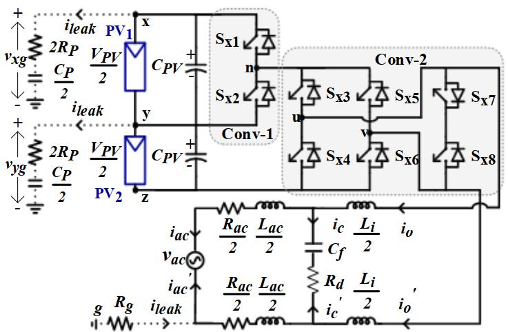
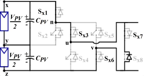
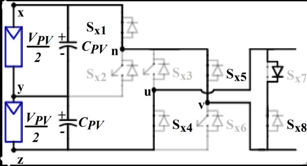
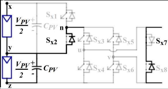
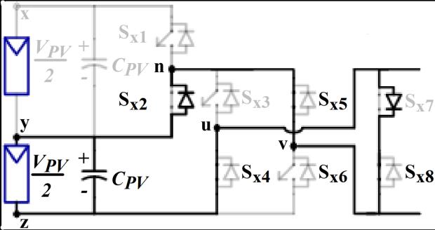
Figure1showstheschematiccircuitdesignofthefivelevel inverter that is suggested for the PV system. Two converters, Conv-1 and Conv-2, compose the provided setup.BothswitchesSx1 andSx2 combineupthehalf-bridge inverterknownasConv-1.Sx3–Sx8 arethesixswitchesthat togethermakeuptheConv-2'sinverterarrangement,which isbothefficient.OutofthesixswitchesinConv-2,anH-bridge circuitismadeupoffourofthem(Sx3 toSx6).InConv-2,the othertwoswitches,Sx7 andSx8,maybeturnedonandoffin both directions. The Conv-1's switches are responsible for producingtheVPV and0.5VPV voltagelevels.
VPV
(b)+Vpv/2
(c)0V
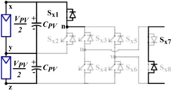
(e)-Vpv/2
The Five level inverter generates five level AC output voltage.Thebehavioroftheinverterateachlevelasshownin Figure2.
International Research Journal of Engineering and Technology (IRJET) e-ISSN: 2395-0056
Volume: 11 Issue: 04 | April 2024 www.irjet.net p-ISSN: 2395-0072
-2:Behaviorofinverterateachlevel
Two separate PV sources are needed for the fiveleveloutputoftheproposedsystem.Bothsymmetricaland asymmetrical configurations of the two PV sources are acceptable. Asa result,as we'll see later on, the suggested PWM approach has to work in both symmetrical and asymmetricalsetupsforthetwoPVsources.
Using a multi-carrier modulation approach determines howwellthemultilevelinverterworks.Multipletriangular carrier signals and a single reference signal are used to construct two-level to multilayer inverters. The created multilayer subharmonic PWM is presented in this work. Figure3demonstratethatmodifiedPWMcontroltechnique forFivelevelinverter,itproduceslessharmonicdistortion whenutilizingsymmetricaltriangularcarriers.
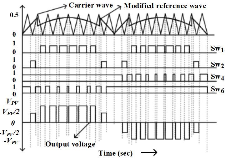
Fig -3:ModifiedPWMcontroltechniqueforFivelevel inverter
AsshowninFigure4,aunittriangularcarrierwaveform multipliedbyratiox2 willproducethenecessarytriangular wave.Theoutputvoltagereachesthelevelof'VPV/2'when theinstantaneousmagnitudeof'vref_modified'isgreaterthanthe magnitudeofthecarrierwave,insidethepositivehalfcycle andforphaseanglesrangingfrom0to30degreesor150to 180 degrees. To keep the fundamental output voltage's
positiveandnegativecyclesinperfectsymmetry,thesame sequenceisusedforthenegativehalfcycleaswell.
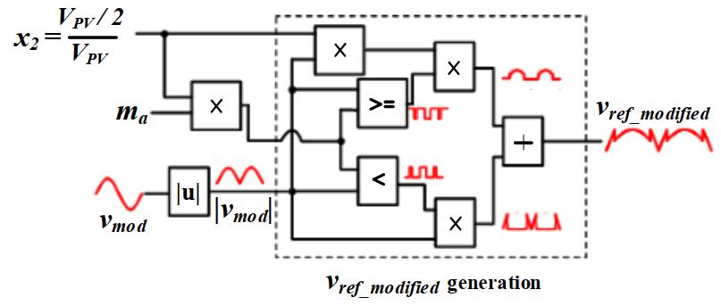
-4:Controltechniqueforproductionofmodified referencewave
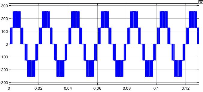
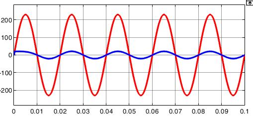
Figure5showsthefive-levelinvertersimulation.Using MATLAB/SIMULINKsoftware,wesimulatedathree-phase, five-levelcascadedmultilevelinvertermodelandfoundthat thesuggestedPWMtechniqueworks.Thefive-levelinverter arrangementwassubjectedtosuggestedPWMapproaches. ThegridrequirestheinvertertoproduceavoltageVrwithan angle δr in order to receive average active power P. In simulations,asystemwithP=5kW,Vr =233V,andδr=0.158 radwasused.Cascadedfive-levelinvertersimulationresults withsuggestedPWMapproachesareshowninFigure 6to Figure10.Theoutputvoltageofthefive-levelinverterafter filterandthematchinggridcurrent"ig"areshowninFigure 7.TherelatedplotsalsodisplayedtheFastFourierTransform ofthefive-level inverteroutputvoltageandtheassociated gridcurrent"ig "areshowninFigure11.Whencomparingthe suggestedPWMapproachtotheusualSPWMtechnique,itis noticeable that the inverter output voltage has somewhat greatermagnitudesofhigherorderharmonics.


Fig -5:MATLAB-Simulinkdiagramoffivelevelinverter withsolarPVintegratedtothegrid
Awell-designedfilter,however,mayeliminatethese higher-order harmonics. The suggested PWM methods exhibit a predominance of harmonic components at frequenciesinmultiplesof25kHz,asseeninFigure12(i) and(ii).Thus,withacut-offfrequencyof25kHz,thefilter's designparametersaresameinbothscenarios.
International Research Journal of Engineering and Technology (IRJET) e-ISSN: 2395-0056
Volume: 11 Issue: 04 | April 2024 www.irjet.net p-ISSN: 2395-0072
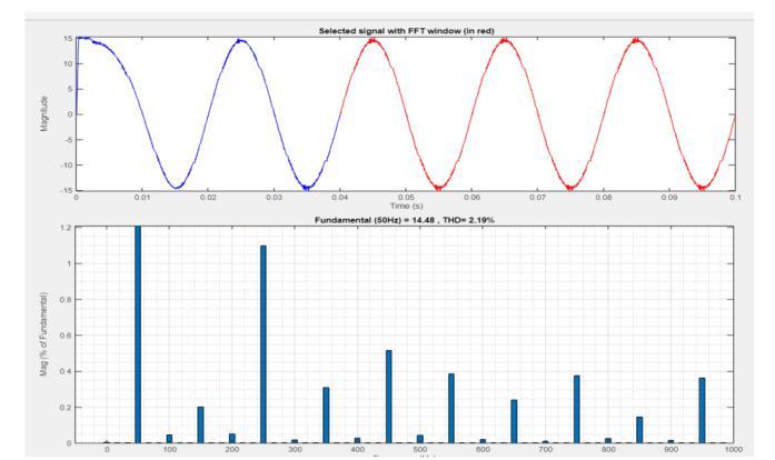
Both the traditional SPWM method and the suggested PWM methodology exhibit the same Total Harmonic Distortion(THD)ofthecurrentwaveform,whichisreadily verifiable. In both instances, the total harmonic distortion (THD)ofthegridcurrentislessthanorequaltotheamount requiredbyIEEE1547standard[33].Accordingtoplotsof Fig.10,anothernoteworthyfindingisthat,inthetraditional SPWM,thecommonmodeandterminalvoltagewaveforms exhibithighfrequencyvoltagechanges.Asdemonstratedin subplots(c),(d),and(f)ofFig.10(ii),thesuggestedPWM approach eliminates or eliminates these high frequency voltage shifts. The findings from the examination of the switching function are consistent with the terminal and commonmodevoltagewaveforms(Fig.9).Theanalysiswas alsojustifiedbythis.ForthetraditionalSPWMmethod,zero sequencecurrentflowsbecausethecommonmodevoltage has high frequency voltage changes. Grid current total harmonicdistortion(THD)couldriseasaresultofthis.
In addition, the waveform for the leakage current of the existingSPWMmethodandthesuggestedPWMmethodare showninsubplots(e)ofFigure10(i)and(ii),respectively. ThesuggestedPWMreducestheleakagecurrenttolessthan 0.1A,incontrasttothetraditionalSPWMwhichhasavalueof around0.2A.Thisisbecausetheterminalvoltages"vog"and "vpg"havealowfrequencyvoltagewaveform.
For the purpose of reducing leakage current, this research examines a single-phase transformer less PV inverterandthePWMapproachthatitemploys.Thispaper proposesamodifiedPWMthatbuildsonthestandardPWM. In several studies, PWM was shown to outperform other methodsintermsoftotalharmonicdistortion(THD),ripples intheoutputcurrent,anddc-linkvoltage.Thelargeleakage current in transformer less PV systems, however, renders thesequalitiesuseless.
Leakage current has reduced the PV systems overall performances and introduced safety concerns. By doing away with zero voltage vector switching, the current
International Research Journal of Engineering and Technology (IRJET) e-ISSN: 2395-0056
Volume: 11 Issue: 04 | April 2024 www.irjet.net p-ISSN: 2395-0072
solution whichemploysmodifiedPWM reducestheCMV andhenceeliminatesleakagecurrent.Whilethesemodified PWMmethodsdoagoodjobofeliminatingleakagecurrent, they pay little attention to the PV systems overall performance. Problems including harmonic distortion, ripplesintheoutputcurrentanddc-linkcurrent,andvoltage linearityhavebeencompromised.
[1] A.Chaudhury,V.Sonti,A.Hota,A.R.SaxenaandS.Jain, "ANewSingle-PhaseFive-LevelNeutralPointClamped Cascaded Multilevel Inverter for Minimization of Leakage Current in PV Systems," 2021 International ConferenceonSustainableEnergyandFutureElectric Transportation(SEFET),Hyderabad,India,2021,pp.15.
[2] G.K,"ImplementationofFiveLevelMultilevelInverter with Reduced Leakage Current," 2022 IEEE InternationalConferenceonDistributedComputingand Electrical Circuits and Electronics (ICDCECE), Ballari, India,2022,pp.1-6.
[3] R.Selvamuthukumaran,A.GargandR.Gupta,"Hybrid MulticarrierModulationtoReduceLeakageCurrentina Transformerless Cascaded Multilevel Inverter for PhotovoltaicSystems,"inIEEETransactionsonPower Electronics,vol.30,no.4,pp.1779-1783,April2015.
[4] Siva, A., Palleswari, Y.T.R., Kadali, K.S., Bhukya, R., Deenakonda, M., Inti, V.V.V. (2024). Single-Phase Grid and Solar PV Integration with 15-Level Asymmetrical MultilevelInverter.InCognitiveComputingandCyber PhysicalSystems.IC4S2023,vol537.Springer,Cham.
[5] S.AsapuandD.Susitra,"NewTopologyofaSingleDC sourceNine-levelAsymmetricalMultilevelInverterfor DC-AC Conversion," 2023 IEEE 3rd International Conference on Smart Technologies for Power, Energy andControl(STPEC),Bhubaneswar,India,2023,pp.1-6.
[6] V. Sonti, S. Jain and S. Bhattacharya, "Analysis of the ModulationStrategyfortheMinimizationoftheLeakage CurrentinthePVGrid-ConnectedCascadedMultilevel Inverter," in IEEE Transactions on Power Electronics, vol.32,no.2,pp.1156-1169,Feb.2017.
[7] X.Zhu,H.Wang,W.Zhang,H.Wang,X.DengandX.Yue, "A Single-Phase Five-Level Transformer-Less PV Inverter for Leakage Current Reduction," in IEEE TransactionsonIndustrialElectronics,vol.69,no.4,pp. 3546-3555,April2022.
[8] Siva Asapu, Rajendran Vanitha, A Novel Asymmetric Multilevel InverterwithReducedNumberofSwitches for Grid-tied Solar PV System, Recent Advances in Electrical&ElectronicEngineering,volume15,issue5, pages379-389,year2022
[9] Mohamad R, Oskuee, R. J. Mohammad, Varzeghan S. Rahim, Khezerlu N. Babak, An Efficient Approach to ReduceLineVoltageTHDinaMultilevelInverterwith Alterable DCSources,RecentAdvancesinElectrical & ElectronicEngineering, volume8, issue 1,pages4-11, year2015
[10] S. Dhara and V. T. Somasekhar, "A Nine-Level TransformerlessBoostInverterWithLeakageCurrent Reduction and Fractional Direct Power Transfer Capability for PV Applications," in IEEE Journal of EmergingandSelectedTopicsinPowerElectronics,vol. 10,no.6,pp.7938-7949,Dec.2022.
[11] M. Shahabadini and H. Iman-Eini, "Leakage Current Suppression in Multilevel Cascaded H-Bridge Based PhotovoltaicInverters,"inIEEETransactionsonPower Electronics,vol.36,no.12,pp.13754-13762,Dec.2021.
[12] A.JakharandN.Sandeep,"Five-LevelCommon-GroundType Boosting Inverter With Lesser Capacitor-Stored Energy,"inIEEETransactionsonPowerElectronics,vol. 38,no.12,pp.15121-15125,Dec.2023.