
International Research Journal of Engineering and Technology (IRJET) e-ISSN: 2395-0056
Volume: 11 Issue: 04 | Apr 2024 www.irjet.net p-ISSN: 2395-0072

International Research Journal of Engineering and Technology (IRJET) e-ISSN: 2395-0056
Volume: 11 Issue: 04 | Apr 2024 www.irjet.net p-ISSN: 2395-0072
H L Tiwari1, Kartikeya Mishra1, Bikram Prasad2
1Professor, Dept. of Civil Engineering, MANIT Bhopal, M.P., India
1Research Scholar, Dept. of Civil Engineering, MANIT Bhopal, M.P., India
2Associate Professor, Dept. of Civil Engineering, BIST Bhopal, M.P., India
Abstract - This research paper describes experimental model studies on stilling basin whichareperformedtodevelop efficient and economical type stilling basin for non-circular pipe outlets for low Froud numbers. The experimental study was carried out for three Froude numbers, namely 3.85, 2.85 and 1.85 for the exit of the non-circular pipe. Performance of models were compared with non-dimensional parameters Performance criteria named as Performance Index (PI). Flow condition and running test hour was kept constant for all the tested model for particular Froud number. After analyzing eighteen tests, it was observed that the performance of the evolved stilling basin model also improved by reducing the basin length from 8.4d to 7d by introducing an intermediate sill of square section and new design of impact wall as comparison to USBRVI model. This model performed better than the USBR VI impact basin for similar flow conditions at a reduced length of 7d from 8.4d where d is the equivalent diameter of the pipe outlet with significant improved performance.
Key Words: Pipe outlet, Stilling basin, Scour pattern, USBR
Thewaterthatcomesoutofanoutletinthetank,whetherit bethroughgates,tunnelsorpipesandoverweirs,comesout at high speed, which is generated by varying its height potential drop from reservoir level to downstream river level (Mylvogonan and Rajaratnam 1961). This velocity is much higher than the natural safe velocity of stream at a givensite,andcausesscouringatthetoeofthedamorother hydraulic structures. This scouring, if allowed to continue willunderminethefoundationwithconsequentdamageto theoutletstructures,theoutletchannelandsometimesthe damitself(GehlotandTiwari2014).Thehydraulicengineers are, therefore, facing with the problem of minimizing the energyofflowingwaterhavinghighvelocityforreducingthe scour below the structure for a long time (Panwar and Tiwari2014)
The hydraulic jump is an excellent tool for dissipatinghydraulicenergy,butitrequiresagreaterlength ofthebasin.Thelengthofthehydraulicjumpandtherefore thelengthofthebasincanbereducedbyusingdevicesinthe formofbaffleblocks,chuteblocks,splitterblocksandend sill,etc.AccordingtoMurthyandDivatia(1982),hydraulic
jump-type stilling basins are the efficient mechanism for dissipatingexcessenergyandtheleastpronetoerosionand cavitation.Thistypeofradiatorhasbeenwidelyused.The hydraulicjumpisalsoassistedbytheuseofcrossjetseither fromthesurfaceorfromthebed.TheUSBRstillingbasins (BradleyandPeterka1957),S.A.F.stillingbasin.(Blaisdell 1948)andI.S.Stillingbasins(2004)fallunderthiscategory. The designs are modified according to the prevalent site conditions(Mazumdar2003).TheS.A.F.stillingbasinsare shorter in length and they are mainly used on low head structures.Animpacttypeofstillingbasiniscontainedina relativelysmallboxtypestructurewhichdoesnothavetail water requirements for proper performance. The USBR impacttypeVIstillingbasinwasmainlydevelopedforthe pipeoutlets.
Toreducethehighenergyofflowingwater,stilling basins are normally used (Tiwari et al. 2010). Dams and other hydraulic structures are planned to control large volumes of high pressure water (Sarma et al. 2009). The energies at the base of the structures are often enormous whether the discharge is through outlet conduits or over spillways.Somemeansofexpendingtheenergyofthehigh velocity flow are needed to prevent river bed runoff, minimizeerosion,andpreventdamweakening.Thiscanbe achievedbyconstructinganenergydissipatoratthebaseof thestructuretodissipateexcessenergyfromthewaterand establish safe flow conditions in the drainage channel (Pramanic and Mazumdar 1961). Any hydraulic energy dissipator'sabilitytofunctionprimarilyliesonitsabilityto useoneorcombinationofthetechniquesrecommendedby Govinda Rao (1961), Yang (1994), and Vischer and Hager (1995)toconsumesomeoftheenergyofthehighvelocity flow.Stillingbasinsareanintegralpartofspillways,outlet works,diversionstructuresandwaterfallstructures(Tiwari 2013A).
Variousdevicessuchasimpactwall,intermediate and end sill etc. are used to make the stilling basin more efficient(Tiwarietal.2014).Theeffectofthesillontheflow orscourcharacteristicsdependsontheconfigurationofthe sill,itsgeometryandtheflowregime,Negm(2004).Various types of stilling basin models recommended for pipeline releases are by Bradley and Peterka (1957), Fiala and Maurice(1961),Keim(1962),VollmerandKhader(1971), VermaandGoel(2000and2003),Goel(2008),Tiwarietal. (2011, 2012, 2013, 2014 and 2015), Tiwari and Gahlot (2012),Tiwari(2013Aand2013B),TiwariandGoel(2014
International Research Journal of Engineering and Technology (IRJET) e-ISSN: 2395-0056
Volume: 11 Issue: 04 | Apr 2024 www.irjet.net p-ISSN: 2395-0072
and2016)andTiwariandSingh(2017).Thedevicesplayan important role in reducing the kinetic energy of running waterinthedesignofthestillingbasinmodel.Astillingtank for the outlet of a pipe consists of accessories such as the dividerblock,theimpactwall,theintermediatesillandan endsill,etc(Tiwarietal.2014).Theverticalsillisaterminal element of the still basin, which greatly contributes to reducingtheenergyoftheflowingbodyofwaterandhelps toimprovetheflowdownstreamofthecanalthushelpingto reduce the length of the stilling basin (Tiwari and Goël 2014). The placement of the sill above the bottom of the stillingbasinhasagreatimpactontheformationandcontrol ofthehydraulicjumpandultimatelyleadstothereduction of the kinetic energy of the flowing water (Tiwari et al. 2022).Severalresearchers,includingNegm(2004),Verma andGoel(2003)suggestedinstallinganintermediatesillto enhance stilling basin performance. Also. based on lab testing, the end sill significantly boosts the basin's effectiveness (Saleh 2004, Alikhani et al. 2010). This researchpaperfocusesonimprovingtheperformanceofthe USBRVIStillingBasinmodelusingthesquaresillpositioned aftertheimpactwallwiththeendsillandimpactwall.The performanceofthestillingbasinmodelsiscomparedtothe performanceindex(PI).Ahigher PIvalueindicatesbetter performance of the still model for the pipe outlet (Tiwari 2013BandTiwarietal.2014).
1.1
Appurtenancesareemployedtopromotethedissipation ofenergyandtherebymakingtheenergydissipatorseffective and economical. For energy dissipation of the pipe outlet, appurtenanceslikesplitterblock,impactwall, endsill,etc. playsimportantroletoincreasetheperformanceofbasinsby reducingtheexcessenergyofflowwithinthebasinlength (Tiwari and Prasad 2017). They not only economize the stillingbasinbutalsohelptoreducethescourofdownstream channel within a permissible limit with a suitable velocity distribution(Elevatorski1959).Thus,theappurtenancesare importanttooltoreducethecostofthestillingbasinandalso providesafetytothehydraulicstructure.
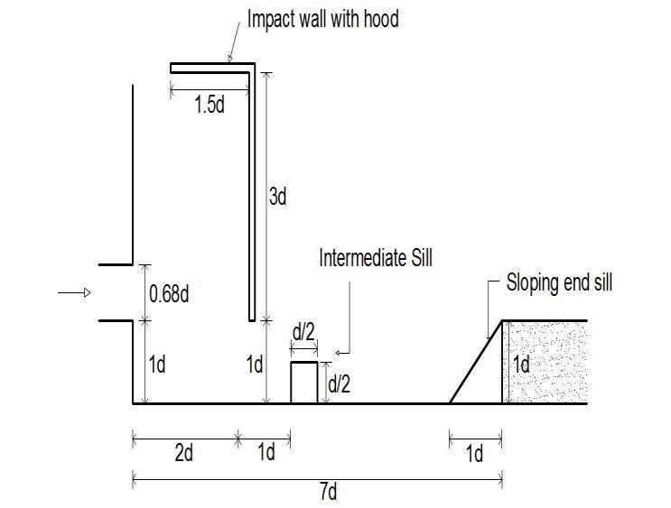
The experiments were carried out in a recirculating laboratorychannel0.95mwide,1mdeepand25mlong.The widthofthechannelwasreducedto58.8cmbybuildinga brickwallalongitslengthtomaintaintheratioofthewidth ofthebasintotheequivalentrectangularoutletdiameterof 6.3accordingtothedrawingbyGardeetal.(1986).A10.8cm rectangulartubex6.3cm.wasusedtorepresenttheoutlet. Theoutletofthetubewasmaintainedabovethestillingtank of an equivalent diameter (1d = 9.3 cm). To observe the scouringafterthefinalsillofthestillbasin,anerodiblebedof coarsesandwasmadewhichpassesthroughtheopeningof the2.36mmscreenandheldovertheopeningofthe1.18mm ISscreen.Themaximumabrasiondepth(dm)anditsdistance totheendsill(ds)weremeasuredforeachtestafteronehour
ofoperation.Theflowdepthontheerodiblebedwaskept equaltothenormalflowdepth.TheUSBRTypeVIstillbasin model proposed by Bradley and Peterka (1957) was fabricatedwithan8''x23''impactwallwitha3.5''x58.8'' hoodcm andan inclined sill with a height of 9.3cm anda basewidthof9.3cm.Theflowwasmeasuredbyacalibrated Venturimeterinstalledinthesupplyline.Withtheoperation of the tailgate, the desiredcondition of constant flow with normaldepthwasmaintained.Afteranhouroftesting,the motorwasshutdown.Thevalueofthemaximumscouring depth (dm) and its position relative to the threshold (ds) werenoted.Firstofallstillingbasinmodelwithoutimpact wallwastestedandnamedasSM-1thenUSBRVIimpactwall wasplacedandmodel(renamedasSM-2)wasagaintestedin asimilarflowconditionasSM-1.Furtherlengthofthebasin wasreducedto7d andmodelsweretestedwithoutimpact wallandwithimpactwallandtheywerenamedasSM3and SM4. Further to improve the performance of the model squaresillwasintroducedandagainmodelwastestedandit was renamed as SM-5. To make the model more efficient impact wall and sill were also introduced and model was tested in similar flow conditions and performance was evaluated and model was re-designated as SM-6. Some modelstestedwithaccessoriesareshowninFigures1to3. Alltestswereperformedforaconstantruntimeofonehour and with the same erodible material for three Froude numbers, i.e. 3.85, 2.85 and 1.85. An additional scouring schemewasalsoperformedandthenatotalof18testswere performedtoevaluatetheperformanceofthestillingbasin modelsusingthesillaswellastheUSBRVIimpactwalland endsill.TheexperimentalschemeispresentedinTable1
Testsonmodelsinthiscategory,animpactwallofsize1d ×2.2dwithaninclinedendsillandanintermediatesillofsize d/2×d/2square(IS)weretestedwithanimpactofvarying thepositionofthewallwhilemaintainingthepositionofthe impactwallitself.Thelengthofthebasinvariedfrom8.4dto 7d.Atthebasinlengthsof7dand6d,theintermediatesillhas been introduced to make the model efficient.Models SM1, SM3andSM6weretestedwithendsillatbasinlengthof8.4d, 7d and 7d respectively. Models SM2 and SM4 were tested withanimpactwallwiththeendsill.AdditionalSM5andSM6 modelsweretestedwithanintermediatesillwiththesame impact wall and end sill as the models tested previously. Some of these models are shown in Figures 1 to 3 and all modelsarealsoshownintabularforminTable2.
Theinvertleveloftheoutletwaskept1dabovethebasin floor.ModelsweretestedforthisdesignFroudenumberand twolowerFroudenumber(Fr=1.85and2.85)wereselected formodeltestingbasedondischargeandotherexperimental constraints. Flow parameters for different tested Froude numbersareshowninTable1
International Research Journal of Engineering and Technology (IRJET) e-ISSN: 2395-0056
Volume: 11 Issue: 04 | Apr 2024 www.irjet.net p-ISSN: 2395-0072
Table -1: FlowParameters
2.3 Criteria for the performance of evaluation for a stilling basin model
Theperformancesofthestillingbasinmodelsweretestedfor a different Froude number (Fr) which is a function of the speedofthechannel(v),themaximumexcavationdepth(dm) anditspositionfromtheendsill(ds).Anewdimensionless number, called the performance index (PI) developed by Tiwarietal(2011)wasusedtocomparetheperformanceof calmbasinmodels.Thisisgivenasfollows:

Where,Vistheaveragespeedofthechannel,dsdistanceof themaximumdepthofscourfromtheendsill,dmmaximum depthofscour,g-accelerationofgravity,sdensityofsand,ρw densityofwater,d50 theparticlesizedistributionsuchthat 50%ofthesandparticleisfinerthanthissize,ahighervalue oftheperformanceindexindicatesbetterperformanceofthe stilling basin model (Tiwari et al. 2022). The value of the performance index for different runs on each model for differentFroudenumbersisshowninTable3.

stilling basin model at basin length 7d with square sill
An experimental work was carried out to design efficient newstilling basin model as comparedto existingUSBR VI design.Firstofallmodel(SM-1)wastestedwithslopingend sill without impact wall and value of PI were found to be 2.03,2.01and2.70forFroudenumber1.85,2.85and3.85 respectively, USBR VI impact wall was placed and again testingofUSBRVImodel(SM-2)wascarriedoutinsimilar flowconditionasfor SM-1andPIvalueswereobtainedas 2.67,2.63and3.42forFroudenumber(Fr)=1.85,2.85and 3.85respectively,whicharehigherthanSM-1stillingbasin model. Thus, the performance of SM-2 model is better as
International Research Journal of Engineering and Technology (IRJET) e-ISSN: 2395-0056
Volume: 11 Issue: 04 | Apr 2024 www.irjet.net p-ISSN: 2395-0072
comparedtomodelSM1,whichincludesonlyendsill.After thatstillingbasinmodellengthwasreducedto7dfrom8.4d andinsimilarflowconditionsmodelSM-1andSM-2were retestedandre-designatedasSM-3andSM-4respectively. ValuesofPIwerecomputedandmentionedinTable2.From Table2,itisobviousthatPIvaluesofmodelSM-3andSM-4 arereducedascomparedtoSM-1andSM-2respectivelyas basinlengthisreducedto7dfrom8.4d.Furthertoimprove theperformanceofthestillingbasinmodelasquaresillwas introduced after impact wall at 4d length from exit of the pipe length as shown in Figure 3 and model (SM-5) was testedinsimilarflowconditionsandcomputedvalues PIare comeoutas 2.40,2.96and 4.2for Fr=1.85,2.85and3.85 respectively,whicharehigherthanthevaluesobtainedfor USBRVImodel(SM-2),whosevaluesare2.67,2.63and3.42 forFr=1.85,2.85and3.85respectively,thusperformanceof model with square sill at basin length 7d is better as comparedtoUSBRVImodelofbasinlength8.4d. Furtherto make more efficient model the design of impact wall was changedasgiveninmodelSM6withbasinlengthof7dand PIvaluesappearedas6.15,5.10and4.20forFr=1.85,2.85 and 3.85 respectively, which are still more than values obtainedforUSBRVImodel (SM-2)atbasinlength8.4d& SM6modelofbasinlength7d.Thus,theperformanceofnew developedmodelwithsquaresillatbasinlength7disbetter ascomparedtoUSBRVImodelofbasinlength8.4dwhichis alsoshowninTable2.Duringthetestrunofthismodel,it wasalsoobservedthatflowwasverysmoothforallFroude numbersandtheamountoferodedmaterialofsandbedwas alsolesserascomparedtoothermodels.
Aftertheanalysis,itwasfoundthatbyintroducing theintermediatesillwithnewlydesignedimpactwall,there isanimprovementintheperformanceofthestillingbasin model. By designing new impact wall, the area of contact with water during impact action increases by which, a reduction in energy is greater, thus improving the performanceofthebasin.Anintermediatesillofadequate heightpromotesenergydissipationinthebasinbyliftingthe filaments at high speed from the bed. Undoubtedly, the performance of the calm basin models improves with the inclusionofthesquaresectionoftheintermediatethreshold, whichalsoconfirmstheresultsofNegm (2004).Asimilar resultwasalsoreportedby TiwariandTiwari(2013)and Tiwarietal.(2014).
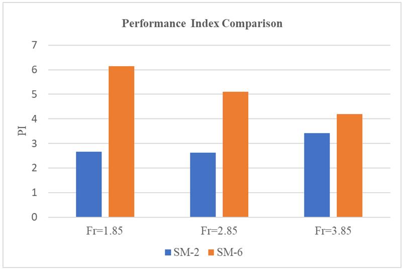
3.1 Comparison of USBR VI model with new Developed Model
On analyzing the USBR VI stilling basin model (SM-2) proposedbyBradley&Peterka(1957)andnewdeveloped stillingbasinmodel(SM-6)fornoncircularpipeoutlet,itis found that the value of performance index are SM-6 (PI = 6.15,5.10and4.20for Fr=1.85,2.85and3.85respectively,) ishighersideascomparedtothevalueofperformanceindex forUSBR-VImodel(PI=2.67,2.63and3.42forFr=1.85,2.85 and3.85respectively)evenatreducedlength from8.4dto
7d. Lookingtotheperformanceitisfoundthatefficiencyof reduction of flowing energy increases by more than 50 percent.Thus,thereisanimprovementofperformancefor thetestedFroudenumberandalsothelengthofthebasinfor newdesignmodelisreducedfrom8.4dto7d.Reductionof thebasinlengthfrom8.4dto7d(17%)makesthenewstilling basinmodel(SM-6)moreeconomicalascomparedtoUSBRVImodel(SM-2)withimprovedefficiencyofmorethan50 percent. ComparativeanalysisisalsoshowninFigure4
Table -2: SchemeofExperimentation
Table -3: Performanceindexfordifferentmodelstested withES,IWandIS
of model
International Research Journal of Engineering and Technology (IRJET) e-ISSN: 2395-0056
Volume: 11 Issue: 04 | Apr 2024 www.irjet.net p-ISSN: 2395-0072
Anexperimentalstudywascarriedoutinthelaboratoryby designingsuitablephysicalmodelsforthedevelopmentofa newmodelofnon-circularpipeoutletsusingthesquaresill as well as the end sill and appropriately designed impact wall according to the USBR VI existing model. The investigationwascarriedoutattwobasinlengths(8,4d,7d) fortheoutletoftherectangularpipewith18testrunforthe Froude numbers 3.85, 2.85 and 1.85. Scouring is reduced there by increasing the performance index for the square intermediatesillplacedatadistanceof4dfromtheoutletof theoutletpipe.Itwasfoundthattheintermediatesquaresill ofheight0.5dandbasewidth0.5d,usedintheSM6model, producedhigherperformanceindices(6.15,5.10&4.20for Fr=1,85,2.85and3.85respectively)whichareevenhigher than the values obtained for the USBR VI (SM2) model of shortlengthof7dfrom8.4dandthereforetheperformance ofthenewmodeldeveloped(SM6)arebetterthantheUSBR VI(SM2)modelforallFroudenumberstested.Basedonthe results of the experimental studies on the stilling basin models,itcanbeconcludedthatthereisanimprovementin performance for the Froude number tested and that the basin length for the new design model is also reduced by 8.4dto7d.Reducingthebasinlengthfrom8.4dto7d(17%) makes the new stilling basin model (SM6) less expensive thantheUSBR-VI(SM2)model
[1] Alikhani,A.,Rad,R.B.,Moghadam,M. F.2010.Hydraulic jumpinstillingbasinwithverticalendsill,International JournalofPhysicalSciencesVol.5(1),Jan. pp.25-29
[2] Bradley, J.N., Peterka, A. J. 1957, Hydraulic Design of Stilling Basins, Journal of A.S.C.E., Hydraulic Engg, , 83(5),1401-1406.
[3] Blaisdell,F.W. 1948.Developmentandhydraulicdesign ofSaintAnthonyFallsstillingbasin.Proc.ASCE,Vol.113, Feb.pp.123-159.
[4] Edward,Elevatorski1959.Hydraulicenergydissipaters, McGraw-HillBookCompany,NewYork.
[5] Fiala, J. R. and Maurice, L. A. 1961, Manifold Stilling Basins,JournalofA.S.C.E.,HydraulicDiv..87(4), 55-81.
[6] Garde,R.J.,Saraf,P.D.,Dahigaonkar,D.J.1986,Evolution of Design of Energy Dissipator for Pipe Outlets, J. of Irrigation&Power, 41(3),145-154.
[7] Gehlot, B. K., & Tiwari, H. L. 2014, Critical review of stillingbasinmodelsforpipeoutletworks,International Journal of Research in Engineering and Technology, 3(6),407-410.
[8] Goel,A.2007.Experimentalstudyonstillingbasinsfor squareoutlets,Proceeding3rdInternationalConference onAppliedandTheoreticalMechanics,Spain,pp.14-16.
[9] Goel,A.2008,DesignofStillingBasinforCircularPipe Outlet. Canadian Journal of Civil Engineering, 35(12), 1365-1374.
[10] Govinda Rao, N. S. (1961). “Energy dissipators below hydraulicstructures”,CBIP,Delhi,SymposiumProc.On EnergyDissipators,pp.42-53.
[11] Keim,S.R.1962,ContraCostaEnergyDissipator.Journal ofA.S.C.E.,Hydraulic Division, 3077,March,,pp.109122.
[12] Mazumdar,S. K. (2003). “Energy dissipation devices”, www.profskmazumdar.com,pp.1-10.
[13] Murthy,Y.K. andDivatia,E.1982.Behaviourofstilling basinsinlargespillways,J.IrrigationandPower39(2), pp.181-188.
[14] Mylvaganam, T. and Rajaratnam, V.N.1961. Energy dissipator below hydraulic structures, Symposium on Energydissipator,CBIP,Delhi.pp.81-98.
[15] Negm, A.M. 2004, Effect of sill arrangement on maximumscourdepthDSofabruptlyenlargedstilling basins,Proc.ofInt.Conf.HydraulicsofDamsandRiver Hydraulics,26-28April,Tehran,Iran.
[16] Panwar, A., and Tiwari, H. L. 2014, Hydraulic energy dissipators-areview,InternationalJournalofScientific EngineeringandTechnology,3(4),400-402.
[17] Pramanic, H. R. and Mazumdar, N. G. 1961, Energy dissipators below hydraulic structures, Proc. Symposium on Energy Dissipators, CBIP, N.Delhi, pp.137-140.
International Research Journal of Engineering and Technology (IRJET) e-ISSN: 2395-0056
Volume: 11 Issue: 04 | Apr 2024 www.irjet.net p-ISSN: 2395-0072
[18] Saleh,O.K.,Negm,A.M.,Waheed-Eldin,O.S. andAhmad, N.G.(2004).“Effectofendsillonscourcharacteristics downstreamofsuddenexpandingstillingbasins”,Eighth International Water Tech. Conf., Alexandria, Egypt, IWTC8,pp.601-613.
[19] Sarma,K.V.N.,Lakshminarayana,P.andRaoLakshmana, N.S.2009.VelocitydistributioninsmoothRectangular openchannel,ASCEJournalofHyd.Eng.Vol.109,No.2, Feb.pp.270-289.
[20] Tiwari, H. L., Gahlot, V. K., and Goel, A. 2010, Stilling basinsbelowoutletworks–anoverview,International JournalofEngineeringScienceandTechnology,2(11), 6380-6385.
[21] Tiwari,H.L.,Goel,A.andGahlot,V.K.2011,Experimental Study of Sill Controlled Stilling Basins for Pipe Outlet, InternationalJournalofCivilEngg.Research,2(2),107117.
[22] Tiwari,H.L.,Goel,A.andGahlot,V.K.2011,Experimental Studyofeffectofendsillonstillingbasinperformance, InternationalJournalofEngg.Sci.andTechnology,3(4), 3134-3140.
[23] Tiwari, H.L, Gahlot, V.K. and Tiwari Seema, 2013, ReductionofScourdepthdownstreamofstillingbasin, InternationalResearchJournalofEngineeringSciences. 2(7),20-25.
[24] Tiwari,H.L.andGahlot,V.K.2012,Experimentsonnew StillingbasinforPipeoutlets,STM,AISECTUniversity, 2(2),17-20.
[25] Tiwari,H.L.2013A,DesignofStillingBasinwithImpact wall and End sill, International Research Journal of ResentSciences,2(3),59-63.
[26] Tiwari, H.L. 2013B, Analysis of Baffle wall gap in the DesignofStillingBasinModels,InternationalJournalof CivilEngineeringandTechnology, .4(4),66-71.
[27] Tiwari,H.L.andTiwariSeema 2013,DesignofStilling BasinModelswithIntermediatesill,JournalofScience, TechnologyandManagement,2(4),pp.66-71.
[28] Tiwari,H.L,Gahlot,V.K.andSharma,A.2014,Effectofof Intermediate sill on the performance of stilling basin models, International Journal of Sc. Engineering & Technology,3(4),414-417.
[29] Tiwari, H. L., Gehlot, V. K., & Tiwari, S. 2014, Effect of HeightofTriangularSiilonthePerformanceofStilling BasinModel,Int.J.Res.Eng.Technol,3,868-873.
[30] Tiwari,H.L.and Goel, A.2014,EffectofEndSillinthe performanceofStillingBasin,AmericanjournalofCivil Engg.andArchitecture,2(2),pp.60-63.
[31] Tiwari,H.L.,Pawar,A.,Gehlot,B.K.,andSingh,J.2014, Study of shape of intermediate sill on the design of stillingbasinmodel,InternationalJournalofResearchin EggandTechnology(IJRET),3(4),133-138.
[32] Tiwari, H. L., Gahlot, V. K., Goel, A., Yadav, S. M., and Tiwari,S.2015,ImprovementofUSBRVIStillingBasin ModelsforPipeOutlet,InE-Proceedingofthe36thIAHR WorldCongress,28June-3July.
[33] Tiwari, H.L. Goel A. and Tiwari Seema, 2015, Effect of Inverted T shape Splitter block in the performance of StillingBasinmodels,ScienceDirect,Aquaticprocedia, Vol.4,pp.1561-1568.
[34] Tiwari,H.L. andGoelA.2016,EffectofImpactwallon Energy Dissipation in Stilling Basin , KSCE journal of CivilEngg. 20(1),463-467.
[35] Tiwari, H.L., & Prasad, B. 2017, Experiments with triangular intermediate sills on stilling basin models, Journal of Basic and Applied Research International, 20(2),139-145.
[36] Tiwari,H.L.andSingh,K.2017,Experimentalstudyon Stilling Basin Models, Resilient Structures and SustainableConstruction,ISECPublication. pp.1-6.
[37] Tiwari,H.L.,Goel,A.,Sharma,A.K.,&Balvanshi,A.2022, Performance improvement of Usbr VI stilling basin model for pipe outlet, In Hydrological Modeling: Hydraulics,WaterResourcesandCoastalEngineering, pp.1-8,Cham:SpringerInternationalPublishing.
[38] Tiwari,H.L.,Hora,M.S.,&Prasad,B.2022,Development of stilling basin models with appurtenances, InternationalJournalOfEngineeringAndManagement Research,12(5),1-5.
[39] Vollmer, E., Khader, M.H.A. 1971, Counter Current EnergyDissipatorforConduitOutlets,InternationalJ.of WaterPower,23(7),260-263.
[40] Verma,D.V.S,Goel,A. 2000,StillingBasinsforOutlets Using Wedge Shaped Splitter Blocks, ASCE Journal of IrrigationandDrainageEngineering126(3),179-184.
[41] Verma, D.V.S., Goel, A. 2003, Development of Efficient stillingbasinsforPipeOutlets,ASCEJournalofIrrigation andDrainageEng..129(3),194-200.
[42] Vischer, D. L. and Hager, W. H. (1995). “Hydraulic StructuresDesignManual,Netherlands.
[43] Yang,S.long(1994).“Dispersiveflowenergydissipater”, ASCE Journal of Hyd. Eng. Vol. 120, No. 12, Dec. pp. 1401-1408