
International Research Journal of Engineering and Technology (IRJET) e-ISSN: 2395-0056
Volume: 11 Issue: 04 | Apr 2024 www.irjet.net p-ISSN: 2395-0072
International Research Journal of Engineering and Technology (IRJET) e-ISSN: 2395-0056
Volume: 11 Issue: 04 | Apr 2024 www.irjet.net p-ISSN: 2395-0072
Vaishnavi
R. Kakade1 , Prerna B. Rajput2 , Ashutosh U. Kale3, Prof Darandale R. A.4
123Student, Dr. Vithalrao Vikhe Patil College of Engineering, Ahmednagar 4Assistant Professor, Dr. Vithalrao Vikhe Patil College of Engineering, Ahmednagar, Maharashtra, India ***
Abstract: PLC is considered an important component in
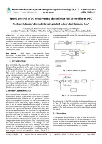
 many different applications. In this paper, PID controller is designed to control motor speed based on input data and automatic maintenance. The control system uses powerful MATLAB and Simulink software for simulation. Simulation results also show that the engine has better performance; This can reduce rise time, steady-state error and overshoot, and improve safety.
Key Words: PMDC motor, Programmable Logic Controller, PID Controller, DC drive, HMI Monitor, High SpeedCounter,GMWINProgramming,MATLABSoftware
DuetothehighefficiencyofDCmotors,thesemotorshave fastswitchingspeedandcanbeusedinmanyapplications. ThebiggestadvantageofusingaDCmotorintoday'sworld is the ability to control the speed and angle of the motor. This project is about controlling the speed of a DC motor using a programmable logic controller. These controllers have advantages over traditional controllers. The advantagesareobvious,suchasreducedcontrolpanelsize, low power consumption and durable equipment that can operatenormallyevenintheworstcase.TheuseofPLCin controlling operations began in 1968 and its development hasbeenveryrapidinrecentyears.
PLCisanimportantpartofthework.WeusePLCtocontrol motorspeed.Firstofall,themotorspeedissenttothePLC bytheshaftencoder,andthenthePLCgeneratesacontrol signalaccordingtotheprogramandPIDcontrollertoreach the desired speed. The analog signal of the D/A module is sent to the DC driver. When the control signal is received, the driver sends the required voltage to the motor. PLC receives the signal from the shaft encoder each time, PLC measuresthemotorspeedandproducesthesignaltoreach the highest speed in the shortest time and complete the process each time, the error is constant and low in the stable state. The HMI monitor displays the coefficients of thePIDcontrollerwiththedesiredspeedandmotorpower andplotsthemotorpoweragainsttime.Additionally,using the HMI buttons, this function can change the PID coefficientsanddesiredmotorspeed.ThePLCusedinthis projectisG7M-DR20UproducedbyLScompany.Onetype ofDCmotoristhepermanentmagnetDCmotor(PMDC).In this project, we use the MFA56VL model, which is a
permanentmagnetDCmotor.Theelectricalcontrolsystem isshowninFigure1.
TheschematicofthePIDcontrollerinthiscircuitisshown in Figure 2.To getthe beststability, overshootand timing we need to adjust the PID parameters manually and analogy. The shaft encoder detects the speed and adjusts thespeed.
In this section, PID controller is used to control the PMDC motor.Simulationisachievedbycalculatingchangesinthe system.Inordertoevaluatetheeffectivenessofthecontrol system, and the changes in the control coefficients in the systemsimulationareshowninFig3,4,5and6.
International Research Journal of Engineering and Technology (IRJET) e-ISSN: 2395-0056
Volume: 11 Issue: 04 | Apr 2024 www.irjet.net p-ISSN: 2395-0072
6. Thestepresponsewithfinalobtainedkd,ki,kp
In Fig 3, Fig 4, Fig 5 and Fig 6, the improvement in performance is clear and significant. By means of appropriate tuning coefficients ki, kd and kp, tuning time, steady-stateerrorandovershootcanbereduced.Thestep responseofthecontrolsystemisabout52.1%overshootas showninFig.3,whichistransferredtoFig.6,whichshows the control quality. If the balance of the DC motor is as follows:
Relations between the torque and the returned magnetic fieldisasfollow:
Ke and Kt are equal amount in SI. According to fig.7 & relationship based on Newton's law and Kirchhoff law have:
International Research Journal of Engineering and Technology (IRJET) e-ISSN: 2395-0056
Volume: 11 Issue: 04 | Apr 2024 www.irjet.net p-ISSN: 2395-0072
DCmotorsarenotlistedinTable1.Thesedimensionsand quantities are determined. Ziegler and Nichols proposed rulesfordeterminingthevaluesofthegainKp,integration time Ti, and derivative time Td based on the dynamic response of the given product. For the Ziegler-Nichols frequency response method, the critical gain Kcr and the critical time Pcr must first be determined by setting Ti = and Td = 0. Increase the value Kp from 0 to the critical valueKcr,theoutputfirstexhibitscontinuousoscillations.
Table
2.2. Hardware Implementation:
In this paper, speed control of DC electric motor designed and simulated and made. The main Required componentstomakeareshowninfig.9.
International Research Journal of Engineering and Technology (IRJET) e-ISSN: 2395-0056
Volume: 11 Issue: 04 | Apr 2024 www.irjet.net p-ISSN: 2395-0072
First, PLC and HMI must be programmed. We use GMWIN to make PLC. We use high speed and automatic tuning to program PLCs. Some programs in GMWIN are shown in figure10.ToconnectthePLCtothePC,weuseaUSBtoRS232converterasshowninfig11.
We use Panel Editor software to program the HMI. HMI allows us to instantly display system faults and critical signals and view errors online. Generally speaking, please followthestepsbelow(shown in Figure 12) tocreate and usetheprogramtosetuptheHMIandPLC.Shaftencoders are used to receive and transmit motor speed. Another component used here is called connection. There needsto be a connection for transmission speed between coaxial and shaft encoders due to the difference between the two shafts.Itisdesignedwith12mminputIDand6mmoutput ID.
Thetwoscrewsintheconnectionbetweenthetwoaxles aretopreventcollision.Thebasisforusingframeencoders. Duetothelowheightoftheencodershaft,weneedasolid base and vibration resistance. Also consider using boards made of MDF to fix everything until everything is stable and not moving. Figure 13 shows the connection between themotorandtheencodershaft.A,BandZoutputsofthe shaftencoderareconnectedtothePLC,andthe24VDCPLC powersupplyisconnectedtotheshaftencoder.Alldetails regarding the construction of this project are shown in Figure14.
International Research Journal of Engineering and Technology (IRJET) e-ISSN: 2395-0056
Volume: 11 Issue: 04 | Apr 2024 www.irjet.net p-ISSN: 2395-0072
When GMWIN software is connected to the PLC, it can monitor the operation and performance of the system. Figure 15 shows the graph from GMWIN software for the 60 rpm setting; It shows that the system reaches the problemquicklywithfewererrorsandovershoots.
In addition, the speed can be adjusted by comparing the measured time with the P, I, D coefficients, and the set value and the current value are displayed on the HMI for monitoring purposes. For example, the engine speed for a 260-rpm setting is shown in figure 16. HMI function buttons are defined. If this function is not defined, this buttonwill notwork.F1,F2,F3,F4keypositionsareused for thedefined functions. The F1keyis settoincreasethe Kp value in steps of 10. The F2 key is set to increase the currentvaluein10steps
To prevent noise from the AC source from being transmitted to the control unit and its equipment and accessories, we use appropriate electrical equipment with filtersandinsulation,andusecableshieldingwithoneside connected to ground. We create legal lines. We are considering two soils, one for PE and the other for CE. Therearetwodifferentpaths,althoughbothareconnected toground.ThecontrollerisconnectedtoCEground.
Whendeterminingtheallowableriseoftheengine,130 °Cshouldbesubtractedfromthetemperature.Itisaclass F electrical insulation type. Ambient temperature can be measured using information such as load performance, engine performance and temperature rise coefficient. The rampfunctionactsasacontroltopreventtheenginefrom startingatlowtemperatures.
Itisanegativevaluethatdescribesthedeflectionasa functionofincreasingtorsionalload.Lookingattheengine chart,theidlespeedoftheengineat200voltsis2000rpm. If the torque load is not connected to the motor shaft, the motorwillrunatthisspeed.Enginespeedunderloadisthe no-load speed minus the speed reduced by the load. The proportionality constant for the relationship between enginespeedandenginetorqueistheslopeofthetorquespeed curve calculated by dividing the engine's no-load speedbythestandingtorque.
Motor load current is the sum of no-load current and loadcurrent.Fora DCmotor,theoutputtorqueisdirectly proportional to thecurrententering the motor, regardless of motor speed. The straight line between torque and currentisthetorque-currentcurve,asshowninfigure17. Thisfigurehasbeendrawntomatchfigure18.
International Research Journal of Engineering and Technology (IRJET) e-ISSN: 2395-0056
Volume: 11 Issue: 04 | Apr 2024 www.irjet.net p-ISSN: 2395-0072
The control system is designed to control the engine very quickly. The engine speed (current value) reaches the set value in a short time with very little overshoot, which is veryusefulinpreventingfloordamageinspeedcontrolin industry. By comparing the simulation results before and after the check, we can conclude that many requirements such as rise time and overshoot have been improved. Simulationandhardwareimplementationshowimproved performance
[1] P. C. Sen, “Electric motor drives and control: past, present and future ”, IEEE Transactions on Industrial Electronics,Vol.IE37,NO.6,1990,pp.562-575.
[2] M. Rashid, "POWER ELECTRONICS Circuits, Devices, andApplications",Prentice-Hall-2thed,1993.
[3] J. Ziegler, N. Nichols, “Optimum Settings for Automatic Controllers,”ASMETrans.64(1942),pp.759-68
[4]K.ogata,"ModerncontrolEngineering",5thed,2010.
[5]T.Krishnan,B.Ramaswamy,”Afastresponsedcmotor speed control system”, IEEE Transactions on Industrial App,vol.,IA-10,No.5,Sept./Oct.1974,pp.643-651.
[6] Z. Wan-zhen, "PLC analysis and design applications", ElectronicIndustryPress,2004.
[7] X. XingMing, "PLC control system reliability design", AutomationandInstrumentation,200