
International Research Journal of Engineering and Technology (IRJET) e-ISSN:2395-0056
Volume: 11 Issue: 04 | Apr 2024 www.irjet.net p-ISSN:2395-0072
International Research Journal of Engineering and Technology (IRJET) e-ISSN:2395-0056
Volume: 11 Issue: 04 | Apr 2024 www.irjet.net p-ISSN:2395-0072
Om Sabu1 , Onkar Pandit2 , Ratansinh Rajeshirke3 , Ramola Sahare4
Student, Department of Mechanical Engineering, All India Shri Shivaji Memorial Society’s College of Engineering, Pune, India
Prof. Dr.P.S. Gajjal, Department of Mechanical Engineering, All India Shri Shivaji Memorial Society’s College of Engineering, Pune, India
This study investigates the potential of utilizing exhaust air from ducts in industrial or ventilation systems as a resource for wind turbine energy generation. The proposed system incorporates specially designed turbines strategically placed within the ducts to capture the kinetic energy of the moving air. Through computationalsimulationsandexperimentalvalidations, this research aims to analyse the feasibility, efficiency, andenvironmentalimpactofharnessingthisexhaustair as an additional renewable energy source. The findings from this study offer insights into a novel approach for maximizing energy recovery from existing infrastructures while contributing to sustainable energyproduction. Utilizing wind turbines to harness the energy potential of exhaust air from ducts presents aninnovativeapproachinrenewableenergygeneration. By strategically placing turbines within these ducts, the kinetic energy of the airflow can be captured and convertedintoelectricalpower.Thismethodtapsintoan otherwise wasted resource, contributing to more efficient energy utilization within industrial or ventilation systems. The design and implementation of such turbines require careful engineering to optimize efficiency and ensure minimal disruption to the airflow. This approach holds promise for enhancing sustainability by tapping into untapped energy sources whilereducingthecarbonfootprintofoperationsreliant onexhaustsystems.
Over the last couple of decades, mankind has realized thatthecontinuoususageofpetroleumfuelstomeetthe world’s energy demand, over the course of more than a century, has led to innumerable consequences. An inclination towards other sources for energy has come into the forefront. Yet, we are still a long way from completely phasing out petroleum as an energy source altogether. In such a time, any progress towards reducing the amount of fuel consumed during energy generation is good progress and cannot be neglected. Therestiswastedintheformofexhaustheatandnoise. So, there is a scope for reclaiming the wasted power producedbytheindustry.
Turbine-based power generation through the exhaust gases has proven to be an efficient source of energy generation.
Turbine Based Power Generation: It works on the principle of conversion of kinetic energy into electric energy. In this process, a turbineisfixednear the opening of the silencer. A dynamo is attached to the turbine, which converts kinetic energy generated throughtheturbineintousefulelectricalenergy.
Efforts are being made to establish more innovative energy generation systems, better in terms of performanceand economy, tocopeup withtheswelling demand of energy. Recovery of the waste energy, i.e., conversionofoneformofwasteenergyintootheruseful form, is one of the important such approaches. Many energy recovery systems are being studied and evolved globallyforusefulpowergeneration.
Waste-to-energy(WtE) energy-from waste(EfW) is the process of generating energy in the form ofelectricityand/orheatfrom the primary treatment ofwaste,ortheprocessingofwasteintoafuelsource.
Industrial waste heat (Exhaust air)is abundant and represents significant energy inefficiency for many processes.
This waste heat energy is carried by Duct systems in various industries, our aim is to generate electrical energy using this exhaust air and increase plant overall efficiency.Ductedexhaustairsystemsareusedtoextract contaminated air from industrial spaces and direct it outside
To fulfil the project, there has to be some calculations that are done prior to the manufacturing process to insure the required outcome and some afterwards. ThesecalculationsarethePowerCoefficient,SweptArea. TipSpeedRatio,��,SpecificSpeedoftheWindmill,Cutin Speed, Cut out Speed, Rated Wind Speed, Torque Coefficient, ����Rotor Solidity, Thrust Coefficients, ����, Wind Power, Efficiency in Wind Power Extraction, TorqueExtracted.
International Research Journal of Engineering and Technology (IRJET) e-ISSN:2395-0056
Volume: 11 Issue: 04 | Apr 2024 www.irjet.net p-ISSN:2395-0072
PowerCoefficient:
The power coefficient is the ratio of the actual power outputtothetheoreticalpowerinthewind.
Power=ForceXVelocity
Force=RateofchangeofMomentum
But:Momentum=MassXVelocity
Forafluidofdensity(ρ).Flowsthroughacross-sectional areaofA,themassflowrateṁisgivenby:ṁ=massflow rate
AverageForce=1/2������ 2
����=1/2������ 3
����=����/����=����(0.125������2�� 3)
SweptArea(AS)
This is the section of air that encloses the wind turbine orwindmillinmovementandinteractswiththerotorsto producetherotationmotion.ForaHorizontalAxisWind Turbine(HAWT),theswept area iscircularinshape.On theotherhand,foraVerticalAxisWindTurbine(VAWT) with straight blade, the swept area us rectangular in shape.
ThesweptareafortheHAWTiscalculatedby:
����=��/4(���� 2)
TipSpeed
Tip Speed Ratio is ratio of the speed of the windmill rotortipatradiusRwhenrotatingatRadianspersecond to the speed of the wind V m/s. When the windmill is stationery, the tip speed ratio is zero; this implies that rotor has stalled. This is experienced when the torque produced by the wind is below the level needed to overcome the resistance of the load. While with a tip speedratioof1,itimpliesthatthebladetipsaremoving at the same speed as the wind (the wind’s angle that is ‘seen’bythebladeswillbe).Whereasatatipspeedratio of 2, the tips are moving at twice the speed of the wind andsoon.
From empirical results, the optimal tip speed ratio to ensure maximum power extraction is achieved for a windmillwithNbladesis:
��=1/4(����/��0)
SpecificSpeedoftheWindmill
This is the angular velocity in revolution per minute at which a turbine will operate if scaled down in
geometrical proportion to such a size that will develop unitpowerunderunithead.
CutinSpeed
This is the speed at which the turbine starts to produce any useful power. It this is the lowest speed at which power develop by the wind turbine ���� is greater than zero.
This is the speed at which the turbine stops to produce any useful power. This is the highest speed at which powerdevelopbythewindturbineisjustzero.
Ratedwindspeed
Wind speed at which the rated power is produced, this valuedefinestheshapeofthepowercurve.
TorqueCoefficient(CT)
The Torque coefficient is the non-dimensional measure ofthetorqueproducedbyagivensizeofrotorinagiven wind speed. This is given as the ratio of the actual Torque produced to the torque due to the force of the windontherotors.
Itisrepresentedmathematicallyby:
����=T/(1/2��������)
Where:
T-Theactualtorqueproduced(Nm)
��0-WindSpeed(m/s)
AS-SweptArea(σ)R:Radius(m)
RotorSolidity
Solidity of a windmill loosely refers to the proportion of a windmill rotors’ swept area that is filled with solid blades. This is the ratio of the sum of the width or ‘Chords’ of all the blades to the circumference of the rotor.
TorqueExtracted
In the windmill used for pumping water, Torque output is key. Torque is given by the ratio power extracted to rotorspeed.
T=(PT/����)
International Research Journal of Engineering and Technology (IRJET) e-ISSN:2395-0056
Volume: 11 Issue: 04 | Apr 2024 www.irjet.net p-ISSN:2395-0072
AND CALCULATIONS
Parameters:
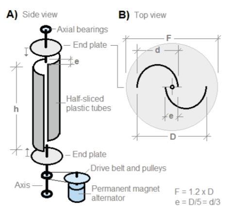
d-Diameterofplasticpipe[m]
D-wingspreadofrotor[m]
e-Pipespacing[m]
h-Heightofblades/tubes[m]
v-Windspeed[m/s]
F-Diameterofendplates[m]
The permanent magnet alternator (Axial flux coreless alternator)produces1Aand12Vatonlyn=130rpmwith anappliedshafttorqueTs=1Nm.
Basic equations
Themaximumpoweroftherotorisestimatedaccording to Betz's law,
Ps =1/ 2 *ρ *A * v3 * Cp =0.36hD * v3 [W]
Where,
ρ=1.2kg/(m3)istheairdensity,
A=h*Dthesweepareaoftherotorblade
Cp=0.593theBetzcoefficient.
However, there are aerodynamic and mechanical losses intheorderof50%.Ourrotorshaftpowerequationthen becomes
Ps = 0.18hD * v3 [W]
Therotationalspeedisdefinedas,
η = (60/2π)*ω [rpm]
Where,
Omega (ω) = λ *v / r is the angular velocity in units of radianspersecond
r = D / 2 the radius of the rotor and λ = 1 the tip-speed ratio
Furthermore,thetorqueattherotorshaftisgivenas,
Ts =Ps* ω [Nm]
It is now possible to calculate key parameters of the rotor using the above equations. For simplicity, the height of the rotor is h = 1m New power and torque valuesasa functionofhisfoundbylinearscalingofthe calculated unit values. The rotor should start spinning forwindconditionsdefinedasmoderatebreezeorwind start speed v = 6 m/s. The results are shown in Table below.
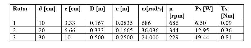
Table1.Moderatebreezewindconditions:v=6m/s andh=1m
Let us now select rotor no. 2 due to the relatively compactsize and the power of-12Wat moderate breeze conditions. Table 2 shows the calculations as a function ofwindspeed.
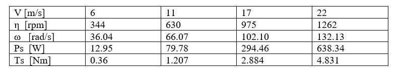
Table2.Powerandtorqueasafunctionofwindspeed forrotorno.2withwingspreadD=33.3cmandgape= 6.66cm.Theheightoftherotorish=1mWindvalues arefrommoderatebreezetoneargale(28-33knots) (force7)conditions
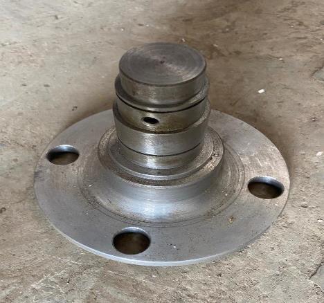
Flanges in turbines arering-shaped connectors that connect the bodies of the steel towers that support the wind turbines.These flanges are an important
International Research Journal of Engineering and Technology (IRJET) e-ISSN:2395-0056
Volume: 11 Issue: 04 | Apr 2024 www.irjet.net p-ISSN:2395-0072
component for tower connection, and are usually installedwithsixorsevenflangesinawindturbine.
Materialused:-MSgradeen8
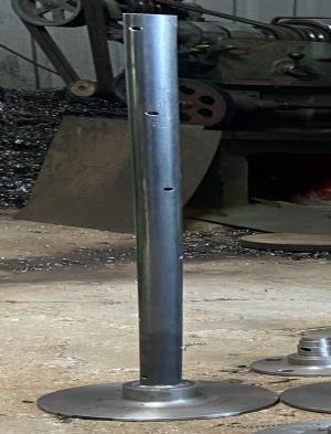
The shaft is responsible for converting the mechanical energy of the blades into the rotational energy and transmittingittothegeneratorwhichinturnusesthisto be converted into electrical work. The shaft in a wind turbine is a critical component that converts the mechanical energy of the blades into rotational energy and transmits it to the generator. The generator then usesthisenergytoconvertintoelectricalwork.Theshaft isalsoresponsiblefortransferringtherotational energy fromtherotortothegenerator.
Materialused:-MSgradeEN8
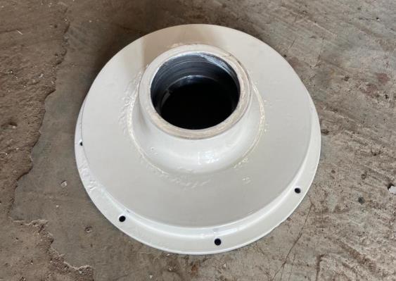
Casing in turbines refers to the outer shell or housing that encloses the internal components of the turbine, such as the rotor and stator.The outer shell or housing ofawindturbineiscalledthecasing,whichprotectsand encloses the turbine's components.The casing can also refertoanenclosingshell,tube,orsurroundingmaterial.
Materialused:-mildsteel(MS)gradeEN8
4) ArmatureCoil
The high-speed shaft is attached to a coil of copper known as an armature inside the generator. The armature rotates at the same speed as the high-speed shaft. The armature is surrounded by a magnetic field, created by magnets within the generator. As the armaturerotatesthrough themagneticfield,acurrentis induced in the copper coil. The electricity generated in thecoppercoilisthenextractedfromthegenerator.
5)
International Research Journal of Engineering and Technology (IRJET) e-ISSN:2395-0056
Volume: 11 Issue: 04 | Apr 2024 www.irjet.net p-ISSN:2395-0072
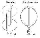
In the original versions of the Darrieus design, the aerofoils are arranged so that they are symmetricaland have zero rigging angle, that is, the angle that the aerofoils are set relative to the structure on which they are mounted. This arrangement is equally effective no matterwhichdirectionthewindisblowingincontrastto theconventionaltype,whichmustberotatedtofaceinto thewind.
Wind turbine blades are typically made from composite materials, including fiberglass, carbon fiber, natural fibers, epoxy, aramid (Kevlar), and wood compounds.Theblades are themost expensivepartof a wind turbine and are subject to dynamic loads, such as gravity, centrifugal forces, and changes in gravity direction.
6) Alternator
A wind turbine alternator is an electrical machine that converts mechanical energy from wind turbine blades into electrical energy to power the turbine. It's a multiphase AC synchronous machine that produces a balancedACvoltageandcurrentsystem.Therotoricand statoric magnetic fields work at the same speed, or rotatesynchronously.
FINAL PROJECT
6.
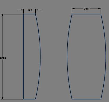
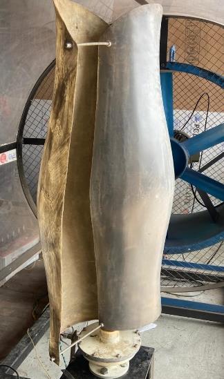
The vertical axis wind turbine, which has two different types of air foil profiles, attains a higher velocity than standard vertical axis wind turbine under the same conditions. The VAWT section with a parabolic blade profilecancapturemoreair,allowingittorotateevenat
International Research Journal of Engineering and Technology (IRJET) e-ISSN:2395-0056
Volume: 11 Issue: 04 | Apr 2024 www.irjet.net p-ISSN:2395-0072
lower wind speeds. The VAWT section with an elliptical air foil profile helps to accelerate the rotation of the parabolic air foil since the elliptical profile is more streamlinedandattainshighervelocities.
Vertical Axis Wind Turbines have the potential to capture wind from any direction since the rotor is perpendicular to the ground. This makes them more efficient in areas with turbulent wind conditions or frequentchangesinwinddirection.VAWTsaregenerally quieter than HAWTs since the blades rotate at a slower speed, resulting in less noise pollution. VAWT having parabolic and elliptical airfoil profiles attain higher velocities than standard VAWT but less velocity than Savonius-Darrieus hybrid VAWT operating under sameconditionsbutbothhavehighervelocitiesthanthe standardVAWTdesign.
1.) The combination of the turbine blades in practical gives the implementation of renewable energy and energy generation to calculatedefficiencyapproximately.
2.) Through rigorous testing and analysis, it was observed that this blade configuration led to improved aerodynamic characteristics, resultinginhigher energyoutputcomparedto traditionaldesigns.
3.) The turbine exhibited stable operation under varying wind conditions, showcasing its reliability and suitability for small-scale renewableenergyapplications.
4.) It is found that slightly change in angle of the turbine blade will result in change in the rpm oftheturbine
5.) Further optimization and fine-tuning of the blade design could potentially yield even greater energy generationcapabilities, making it a promising technology for sustainable energyproduction.
6.) In theoretical calculation we got 3-4 m/s of wind speed at which the turbine will start to rotate but in practical testing we got 6 m/s at whichturbinestartsrotating
REFERENCES
1) Wind Turbine System Design: Nacelles, drivetrains and verification (Energy Engineering)-JanWenske
2) http://airfoiltools.com/
3) https://www.researchgate.net/publication/323 589645/figure/fig6/AS:601336995409920@15 20381320857/Standard-types-of-vertical-axiswind-turbines-13.png
4) S.Brusca,R.Lanzafame,M.Messina."Designofa vertical-axis wind turbine: how the aspect ratio affectstheturbine’sperformance".2014.
5) Mats Wahl."Designing an H-rotor type Wind TurbineforOperationonAmundsen-ScottSouth PoleStation".2007.