
International Research Journal of Engineering and Technology (IRJET) e-ISSN:2395-0056
Volume: 11 Issue: 04 | Apr 2024 www.irjet.net p-ISSN:2395-0072
International Research Journal of Engineering and Technology (IRJET) e-ISSN:2395-0056
Volume: 11 Issue: 04 | Apr 2024 www.irjet.net p-ISSN:2395-0072
A.B.Raghul1 , S.Kalaimani1, A.B.Rakkesh3, V.Arunachalam4, A. Arun5
2Assistant Professor, Department of Mechatronics, Sri Manakula Vinayagar Engineering College, Madagadipet, Puducherry, India
1345UG student, Department of Mechatronics, Sri Manakula Vinayagar Engineering College, Madagadipet, Puducherry, India
Abstract - The research seeks to explain the balancing capability of the robot even under external disturbances The study seeks to explain the advantages as well as disadvantages possessed through the application of stepper motor. The study seeks to explain elaborately about the uses of self balancing robot The researcher has used secondary data to extract resources regarding the completion of the study. At final, the comparative results of and gyroscope are derived.
Key Words: self-balancing robot, Stepper motor, Arduino UNO, Bluetooth
1.INTRODUCTION
Self-balancing robot is defined as a robot which has the capability to balance itself on two wheels and get controlledbytheuserevenunderexternaldisturbances. Self-balancing robot consisting of both hardware and software components such as housing, motors, and Bluetoothmodule.Self-balancingrobotisgenerallyused to carry the hazardous substances like chemicals in chemical industry and used in vehicles to safeguard the physicallyimpairedpersons
1.1 APPLICATION
Other applications of the Self-balancing robot such as military, medical applications and it is used for gardening which is controlled by the Internet of things(IOT) , airports for carrying luggage , automatic trolleysinthemallsandsupermarket.Themainpurpose oftheSelf-balancingrobotistoopposetheexternalforce from the environment and maintaining its upright position. Gyroscopic sensor(MPU6050) helps to retain its balanced position from the opposite forces with the help of Arduino controller which acts swiftly on the calibratedtiltangle.
The various methods of algorithms used are Kalman’s
the artificial neural networks. The PID algorithm is an excellentmethodofbuildingacontrolsystemPIDstands for Proportional, Integral, Derivative. The Proportional, Integral, Derivative(PID) parameters such as Kp, Ki, Kd areusedtoimprovethetransientresponse,improvethe steady state response and to improve the transient response settling time and rising time respectively. The Proportional, Integral, Derivative(PID) helps to provide theSelf-balancingrobottomakefastandstableresponse eveninsteepysurfaces.
Thevariouscomponentswhichareusedtoin theselfbalancingrobotare
RechargeableBattery
Gyroscopesensor
Bluetoothmodule
Steppermotor
A4988steppermotordriver
ArduinoNano
ArduinoIDE
Bluetoothterminal
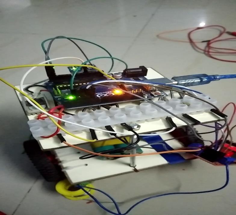
An array of parts is usually included in a self-balancing robot, such as: the robot’s main frame, or chassis, is where all other parts are mounted. Space for mounting wheels, motors, and other gear is typically included. Typically,self–balancingrobotsusetwosteppermotors, one for each wheel. With the help of these motors, the robotcanmoveitswheels.Therobot’swheelsallowitto move and get traction. Often, motor shafts or gears are used to connect them to the motors. These electrical parts regulate the motor’s speed and orientation. They adapt the power provided to the motors based on the signals they get from the microcontroller (such an Arduino). The robot’s microcontroller, which processes sensordata,isitsbrain.
The Bluetooth module is used to control the robot forward and backward wirelessly. And the Bluetooth filter algorithm, LIDAR based G-mapping algorithm and
International Research Journal of Engineering and Technology (IRJET) e-ISSN:2395-0056
Volume: 11 Issue: 04 | Apr 2024 www.irjet.net
terminal software is implemented by connecting the personal computer of laptop IP address to Bluetooth module. The range of the Bluetooth module is nearly from0<100metres.
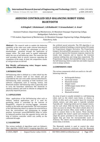
Self-balancing robots frequently use rechargeable batteriesbecauseoftheirportability,energydensity,and capacity to supply the required power for the robot to function. Rechargeable batteries are commonly integrated into self-balancing robots. In order To run their motors, sensors, and control systems, selfbalancing robots need a power supply. Because of their high energy density, rechargeable batteries especially lithium-ion batteries are preferred because they can supply enough power while maintaining an acceptable total weight for the robot .The self-balancing robot's unique requirements determine the battery voltage and capacity to use. More powerful motors might benefit from higher voltage batteries, while greater capacity batteriesofferlongerrunningintervalsbetweencharges.
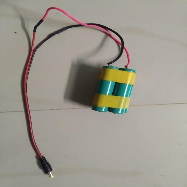
A gyroscope sensor is essential to a self-balancing robot'sabilitytosenseitsdirectionandkeepitsbalance. The rate of rotation around the gyroscope sensor's axis is measured by the sensor. The sensor continuously measures these rotational changes to ascertain the orientation of the robot in relation to its initial position. The robot's control system receives input from the gyroscope sensor and utilizes it to modify the motor speeds as necessary. For instance, if the robot begins to tilt forward, the gyroscope recognizes this abnormality in orientation and notifies the control system to accelerate the motors propelling the wheels backward, reversingthetiltandpreservingequilibrium.
p-ISSN:2395-0072
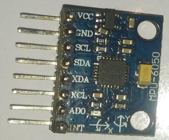
For wireless connection between the robot and a smartphone or other Bluetooth-enabled devices, selfbalancing robots frequently use the HC-05 Bluetooth module. Using an app on a smartphone or a separate remote-control device, users can operate the selfbalancing robot remotely with the HC-05 module. To control the robot's motions, users can transmit commands like stop, left, right, forward, and backward. Users can modify the PID controller gains, maximum speed,andturningsensitivityoftheself-balancingrobot viatheBluetoothconnection.Thisallowsthebehaviorof the robot to be adjusted to accommodate various operatingsituationsorpreferences
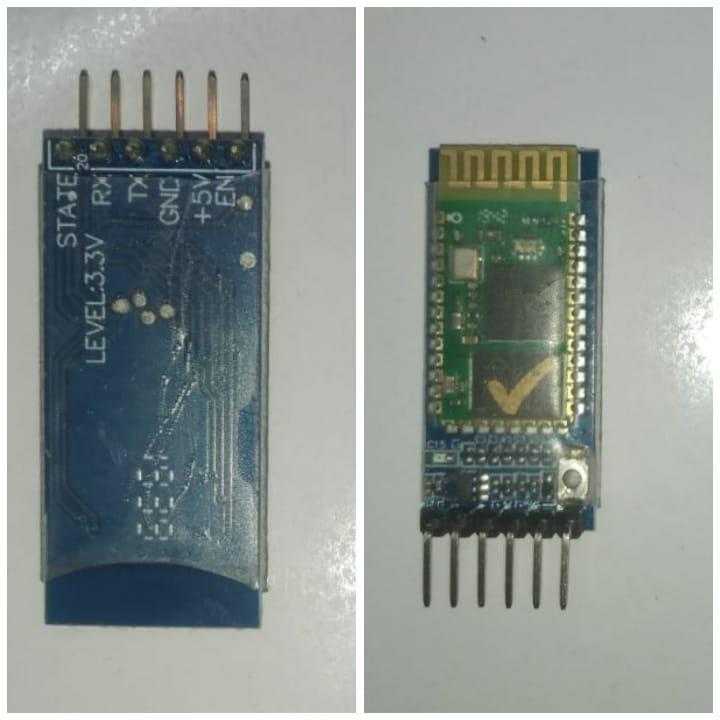
Fig-2.3: Bluetooth Module
International Research Journal of Engineering and Technology (IRJET) e-ISSN:2395-0056
Volume: 11 Issue: 04 | Apr 2024 www.irjet.net p-ISSN:2395-0072
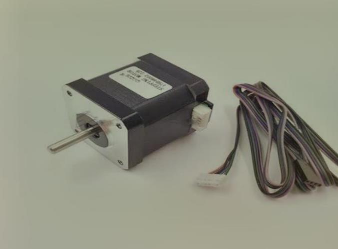
Fig-2.4:
A self-balancing robot can use a stepper motor, albeit thisislesspopularthanemployingbrushlessDCmotors orDCmotors.Althoughsteppermotorspresentaunique set of difficulties, they also have certain qualities that make them appropriate for particular uses. Using a stepper motor in a self-balancing robot can be approached in the following general ways. An inertial measuring unit (IMU) of some kind is usually used by self-balancing robots to determine their tilt angle. The robot's balance is then maintained by using this data to regulate the motors .Stepper Motors is used for the abilitytopreciselyplaceandmaintainapositionwithout constantfeedbackispossessedbysteppermotors
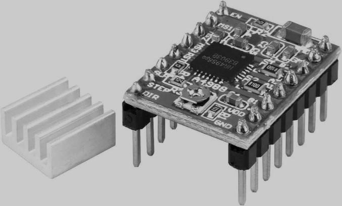
Thecomplexmechanicsofaself-balancingrobotheavily relyontheA4988steppermotordriver.Byemployinga pulse-width modulation (PWM) control system, the A4988 effectively manages the power provided to the stepper motors, guaranteeing accurate and stable movement. With features like microstepping, which breaks up each step into smaller amounts, this driver allows for smoother mobility and more precise control over the robot's balance. The A4988's microstepping
capabilities is invaluable in the context of a selfbalancingrobot,whereexactadjustmentsarecriticalfor preserving equilibrium. Moreover, the integrated safety features prevent overheating and overcurrent, so preventing possible harm to the motor and the entire system.TheA4988steppermotordriverstandsoutasa keyelementinduetoitsadaptability,dependability,and capacitytoprovidesteadyperformance.
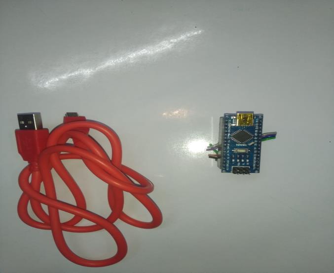
AnArduinoNanocanbeusedinaself-balancingrobotto provideasmallandflexiblemicrocontrollerplatformfor managingseveral aspectsof therobot's functioning .The orientation, acceleration, and wheel speed of the robot may be measured by the Arduino Nano by utilizing sensors like gyroscopes, accelerometers, and encoders. The Arduino Nano can produce PWM (Pulse Width Modulation)signals,whichcanbeutilizedtoregulatethe speed of DC geared motors with the use of a motor driverliketheL293D.TheArduinoNanocancontrolthe PWM signals to maintain balance and speed of the motors by modifying them in response to sensor feedback.
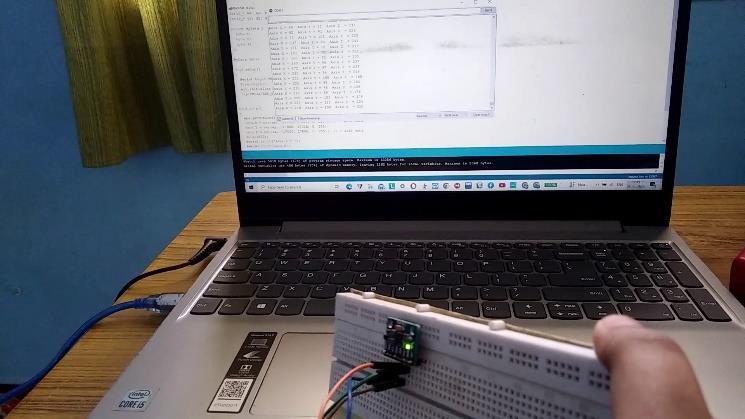
To build the code that governs the behavior of the selfbalancing robot, programmers utilize the Arduino IDE. Usually,thiscodecontainsalgorithmsforreadingsensor data, putting control techniques (like PID control) into
International Research Journal of Engineering and Technology (IRJET) e-ISSN:2395-0056
Volume: 11 Issue: 04 | Apr 2024 www.irjet.net p-ISSN:2395-0072
action, and managing motor speeds. The Arduino IDE is used to compile the code after it has been written. The Arduino IDE makes sure that the code is free of errors and transforms it into instructions to the Arduino microcontroller . The Arduino Nano, a microcontroller board frequently used in self-balancing robots, may be programmed,compiled,anduploadedusingtheArduino Integrated Development Environment (IDE) software platform.
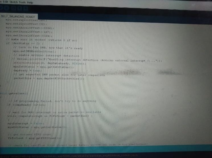
Fig-2.7: Arduino IDE(code)
2.8 ARDUINO BLUETOOTH ROBOT CAR
Theintricateinteractionbetweensensors,actuators,and control algorithms is orchestrated by the Arduino Bluetooth robot vehicle software, which acts as the digital brain behind the operation of a self-balancing robot. By using Bluetooth connectivity, this software enables users to easily monitor and manage the robot's motions remotely. It also enables real-time communication between the robot and external devices, like smartphones or tablets. In order to continuously determine the robot's orientation and make exact modifications to preserve balance, complex algorithms withinthesoftwareevaluatedatafromonboardsensors, including gyroscopes and accelerometers. In order to adjust motor responses and maintain stable, smooth operation even in dynamic situations, it also integrates feedback loops and PID control algorithms. Self-
balancing robots are made possible by the Arduino Bluetooth robot car software's flexible and robust programming.
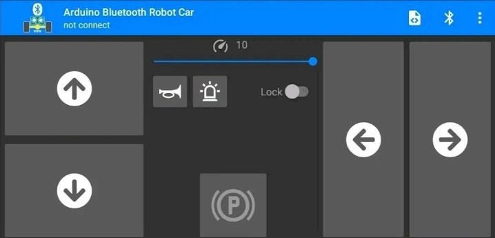
Fig-2.8: ARDUINO Bluetooth Robot Car
2.9 SPECIFICATION OF THE COMPONENTS
S.No Components/Equipments Specifications
1 RechargeableBattery Lithiumion(3.3V each)
2 Gyroscopesensor MPU-6050
3 BluetoothModule HC-05
4 Steppermotor Nema17
5 Motordriver L293D
6 ArduinoNano Atmega328
Fig-2.9: Specification of the component
Sensors, motors, a microprocessor, and a control algorithm are usually used by a self-balancing robot to keep its equilibrium. Sensor is used to assess its orientation and identify any tilt or inclination, the robot makesuseofsensorslikegyroscopes,accelerometers,or anInertialMeasurementUnit(IMU).Themicrocontroller, like an Arduino or Raspberry Pi, processes these sensor signalsanddeterminesthe presentpositionoftherobot as well as the amount of adjustment required to keep it balanced.ThethirdcomponentistheControlAlgorithm. This algorithm uses sensor data to calculate the necessary modifications to keep the robot upright. It is commonly a PID (Proportional-Integral-Derivative) controller.Accordingly,it modifiesthe motors'direction and speed. and the main aim of the self-balancing robot is to balance the Two wheeled Self-balancing robot using Arduino controller to process the data and Bluetooth technology(HC-05 module) to control the robot wirelessly via Bluetooth terminal software. The Bluetooth commands can be given through serial monitor using Arduino IDE software. The Stepper motors(NEMA17)areusedtomakeaprecisemovement andreducevibration.
International Research Journal of Engineering and Technology (IRJET) e-ISSN:2395-0056
Volume: 11 Issue: 04 | Apr 2024 www.irjet.net p-ISSN:2395-0072
The acronym PID represents Proportional, Integral, and Derivative. The input for this technique is the received errorsignal.Andtheerroneoussignalissubjectedtothe subsequentequation.
U(t) = Kp*e(t) + Kd*d/dt(e(t)) + Ki*integral(e(t)) (1.1)
This involves the computation of the integral and derivativeoftheerrorsignals.Thesearethenmultiplied by the corresponding constants and combined with the constant Kp multiplied by e(t). After that, the actuator receives the output, enablingthe system to function. Let us examine each component of the function one by one now. The peak overshoot, settling time, rise time, fall time, and steady state error are all directly impacted by this function. This component lowers the steady state error and rising time. This implies that the system will getatitsdestinationfaster.
Foraself-balancingrobottooperatesteadily,calibration is essential. This is an in-depth analysis. Mechanical calibration is to Verify that the robot's center of gravity isappropriatelypositionedaboveitswheels.Thisentails ensuring that parts like wheels, chassis,and engines are aligned. Small alignment errors can have an impact on balance. Most self-balancing robots use accelerometers and gyroscopes for measuring tilt and acceleration (see Sensor Calibration). To ensure reliable readings, they mustbecalibratedbysetting theirzerovalues.Software calibration algorithms or manual offset adjustments can be used to accomplish this. PID Tuning is used in the motor balance is maintained by the PID controller modifying them. Proportionate (P) is used to responds to the existing inaccuracy (difference between the intendedandactualangle).
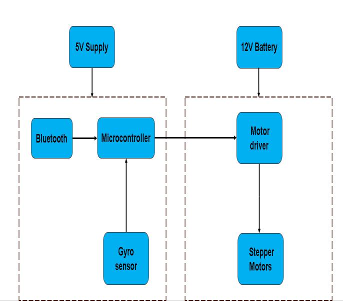
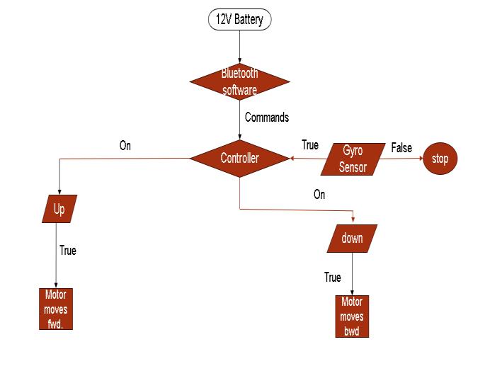
Functional block diagram of self-balancing robot
International Research Journal of Engineering and Technology (IRJET) e-ISSN:2395-0056
Volume: 11 Issue: 04 | Apr 2024 www.irjet.net p-ISSN:2395-0072
The system is powered by a 5V Supply. The Bluetooth module enables wireless connectivity to other devices, likecomputersandcellphones.Microcontrollergivesthe motor driver instructions, interprets sensor data, and manages the robot's general operation. The robot's tilt andorientationaremeasuredviatheGyroSensor.Motor Driver is used to apply the commands from the microcontroller to the motor(s) in order to operate them.StepperMotorisusuallyemployedforfinecontrol, like regulating a self-balancing robot's movement or equilibrium. DC Motor is used to power actuators like wheels. The DC motor and stepper motor are powered bya12Vbattery.
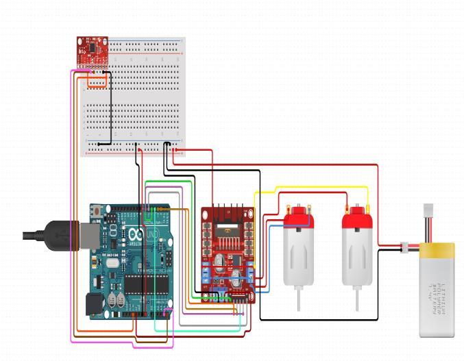
Fig-3.3: Circuit diagram of the self-balancing robot
Dependingontheinterfaceofthesensor,eitherdigitalor analog input pins are used to connect the gyroscope sensor to the Arduino Nano. Serial communication (usuallyutilizingUARTpins)isused tolink theArduino NanototheBluetoothmodule.Tocontroltherotationof the stepper motor, the motor driver is connected to the digital output pins of the Arduino Nano. The stepper motor's power and control signals are linked to the motor driver's output terminals. The Arduino Nano and the motor driver are both powered by the battery. This circuit diagram serves as the foundation for the hardwarearchitectureoftheself-balancingrobot,which can be controlled and monitored wirelessly in addition tobeingabletosensedirection,processinformation,and modifymotiontomaintainbalance.
Thelithium-ionbatteryisusedinthisprojecttoimprove thepowersupplyforlonghoursanditcanberecharged faster. The robot angular movements are sensed by the gyroscopic sensor and sends the signal to the microcontroller.Themicrocontrollermanagesthemotor driver to allow the motor either in clockwise or counterclockwisedirection.Thesteppermotorswill run basedonthemotordrivercommandstobalancingitself. TheBluetoothmodulehelpstocontroltheself-balancing robot wirelessly. The ultrasonic sensor is used in this projecttoidentifytheobstaclesinthesurroundings.The DC motor is used to make the arm to pick and place the objectsitself.
In conclusion, the self-balancing robot project provides insightful knowledge on wireless communication technologies, robotics, control systems, and sensor integration. To sum up, the self-balancing robot project integrates several parts and technologies to produce a dynamic and communicative system. We can create a robot that can keep its equilibrium on its own by combining gyroscopic sensors, motor drivers, stepper motors, Bluetooth modules, and microcontrollers like Arduino Nano. We have studied the fundamentals of feedbackcontrolsystemsduringtheproject,focusingon the PID (Proportional-Integral-Derivative) algorithm, which is essential for stabilizing the robot because it continuously modifies motor output in response to sensorinput.Furthermore,theprojectgainsadaptability and user engagement from the addition of a Bluetooth module, which allows remote control and behavior monitoringoftherobot.Thisprojectwillbesuccessfulin achieving its aim to balance a two-wheeled selfbalancing autonomous robot based on the inverted
International Research Journal of Engineering and Technology (IRJET) e-ISSN:2395-0056
Volume: 11 Issue: 04 | Apr 2024 www.irjet.net p-ISSN:2395-0072
endulum model. This self-balancing robot must change its position to maintain balance even an external force applied is not a problem only stability is considered. However,iftherobotisinanarrowspace,themovement causedbythedisturbancecancreatearealproblem.
[1] Iulian Matesica, Mihai Nicolae, Liliana Barbulescu, Ana-Maria Margeruseanu, “Selfbalancing robot implementing the inverted pendulum concept,” in 15th RoEduNet Conference: Networking in Education and Research,Bucharest,Romania,2016.
[2] Arduino. (2015). Arduino Software (IDE). (Arduino) Retrieved December 27, 2015, from https://www.arduino.cc/en/Guide/Environmen t.
[3] Ahasan, M. A., Hossain, S. A., Siddique, A. U., & Rahman M.M(2012). Obstacle invariant Navigation of An Autonomous Robot based on GPS.KhulnaUniversity.
[4] Sahib, F., Ullah, M. W., Hasan, M. K., & Mahmud, H. (2013). Obstacle Detection and Object Size
Measurement for Autonomous Mobile Robot using Sensor. International Journal of Computer Applications.
[5] Qiu, J.; Wu, J.; Jin, S.; Jin, Y.; Shi, J. Research on Inspection robot of Coal mine Water pump House based on Optimized Fast-SLAM. Coal Eng. 2021, 53,139–145.
[6] Qiao, L. Research On Control Strategy of TwoWheeled Self-Balancing Robot. Ph.D. Thesis, Harbin Engineering University, Harbin, China, 2019.
[7] Lin,X.;Zhang,S.;Chen,J.;Zhao,Z.Finiteelement simulation analysis integrated information model based on Design Reuse. Comput. Integr. Manuf. Syst. 2009, 15,2296–2302.
[8] Wang,X.DesignofTwo-WheelBalancingVehicle System Based on Genetic PD Control. Ph.D. Thesis, Harbin University of Science and Technology,Harbin,China,2018.