
International Research Journal of Engineering and Technology (IRJET) e-ISSN: 2395-0056
Volume: 11 Issue: 04 | Apr 2024 www.irjet.net p-ISSN: 2395-0072
International Research Journal of Engineering and Technology (IRJET) e-ISSN: 2395-0056
Volume: 11 Issue: 04 | Apr 2024 www.irjet.net p-ISSN: 2395-0072
1Mr.Shubham Choudhari, 1Mr.Ganesh Takmoge, 1Miss.Chandani Raut, 1Mr.Kiran Pingale, 1Miss.Nisha Ghate
1B.E Students, Dept. of Mechanical Engineering, Jayawantrao Sawant College of Engineering, Hadapsar Pune, Maharashtra.
Abstract - This research explores the application of Finite Element Analysis (FEA) software in optimizing the structural design of a wheel rim for enhanced performanceanddurability.Thestudyaimstoaddressthe need for light weight yet robust wheel rims to improve vehicleefficiencyandsafety.Inthisstudytheoptimization is done by modifying the design and using different material which plays significant role in weight reduction. FEA is used for investigation the stress and deformations which occurs in the wheel rim. This comparative study helps us to analyze the optimal rim without affecting its strength.
Key Words: Finite Element Analysis, Optimization, Deformation, Efficiency & Safety.
1. Introduction
The structural optimization of wheel rims is a critical endeavor in the automotive industry, aiming to enhance the performance, safety, and efficiency of vehicles. Finite Element Analysis (FEA) has emerged as an indispensable tool in this pursuit, enabling engineers to simulate and evaluate the mechanical behavior of wheel rims under variousloadingconditions.
This process not only facilitates the identification of weaknesses in existing designs but also empowersengineerstoiterativelyrefine&optimizewheel rim structures to meet the demanding requirements of modern vehicles. In this study, we delve into the realm of structural optimization of wheel rims using FEA, exploringthemethods,challenges,andbenefitsassociated withthisinnovativeapproachinthepursuitofsafer,more durable, & high-performance wheels for the automotive industry.
Nowadays optimization has become crucial due increase in global demand of mechanical components. While doing the optimization of components the economical factor must be satisfied. This Research revolves around optimization of wheel rim. This can be achievedbyusingmodelingsoftware.
Dr. B. Venkata Shiva, Y. Vara Prasad Ram [1] et.al have considered Al7068 material due to its strength to weight
ratio, this study examines the wheel rim of Kia Carnival Prestige vehicles using CAD/CAE tools. This research identifies Al-7075 and Al-7068 materials as suitable for structural weight, good natural frequency range, and high safety factor values. This could lead to reduced fuel consumption and improved vehicle performance. The meshing process converts the wheel rim into small particles using elements and nodes, providing more accurate results for real-time applications. The vehicle's speed is 150kmp/h, and the 3members load is 24271N. The best material was selected for its ability to withstand high speed and maximum boundary load conditions, considering3to5-and7-members’loads.
Rajat Yadav, Kamal Sharma [2] et.al this research paper discusses the importance of wheels in vehicle performance,focusingonalloywheelsthatreducevehicle weight. The study uses CATIA software to design and optimizewheelhubsusingfiniteelementanalysisonthree composite materials: magnesium, aluminum, and steel. The research was conducted in two phases, starting with fatigueanalysisanddesignandoptimizationanalysis.The analysis also included stress strain, parameters, car rim geometry, and loading conditions. Cad models were created using CATIA v5 tools, and finite element analysis wasusedtofindvariationsincomplexregions.Theresults showed that Mg alloy has less stress compared to other materials, optimizing wheel design for vehicle load, increasing life expectancy, flexibility, and efficiency. Reducingrimweightalsoimprovedoverallefficiency.
Karikalan Loganathan, S.K. Vijaya Siva Subramani [3] et.al this research aims to optimize the wheel rim of a vehicle by using aluminum alloy Al6061-T4 and magnesium alloy AZ80. The existing design is being studied and optimized to achieve a weight reduction of nearly 58.33% without compromising safety parameters. The cost of aluminum alloy is found to be lower than magnesium alloy. The researchbeginsbyidentifyingtheneedfortheprojectand collecting data on future research scope. A preliminary design is created and analyzed using SolidWorks 2021 software.Aluminum6061ischosenforthewheelrimdue to its lower cost and safety factor of 2.09 compared to magnesium alloy AZ80's high factor of 4.03. ANSYS 2021 R1 Academic is used for analysis, supporting the ongoing development of innovative technology and a processcentricapproachtodesign.
International Research Journal of Engineering and Technology (IRJET) e-ISSN: 2395-0056
Volume: 11 Issue: 04 | Apr 2024 www.irjet.net p-ISSN: 2395-0072
TheobjectivesoftheProjectareasfollow:
To improve the existing structure for better performance.
Reduce weight of wheel rim by modifying its design.
Comparison of wheel rim by using different alloy materials.
There are number of cars which are still using solidwheel rim. It hashigh weightintheir respective rim segment. High weight means high mass due to which the cost requires to manufacture rim increases; hence a typical solid wheel rim of Hyundai Santro Car has taken forAnalysis.
Solid rim CAD Model was prepared in Creo Parametric 4.0 and the analysis is done by giving suitable constrainsandboundaryconditions.Comparisonbetween various metal alloys is done in ANSYS Workbench Software.ThiscomparisonhelpedtoobtainsuitableAlloy. Theprojectworkincludedfollowingsteps,
1) Study of literature Review related to Finite Element Analysis.
2)Theactualdimensionsofwheelrimweremeasuredand cross-verifiedfromweb.
3) CAD model of wheel rim is created with the help of Sketch, Mirror, Revolve, Extrude, Pattern, and Chamfer commandetc.FromCreoParametric4.0
4)The.igsfileisexportedfromCreoParametric4.0
5) For FE Analysis, the rim .igs file is imported in ANSYS Workbench Software & following boundary and loading conditionsareappliedonrimgeometry.
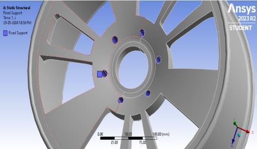
i. thefixedsupportisappliedatnut-boltholes.
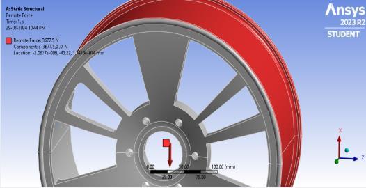
ii. remote location force is applied over the circumferenceofrim.
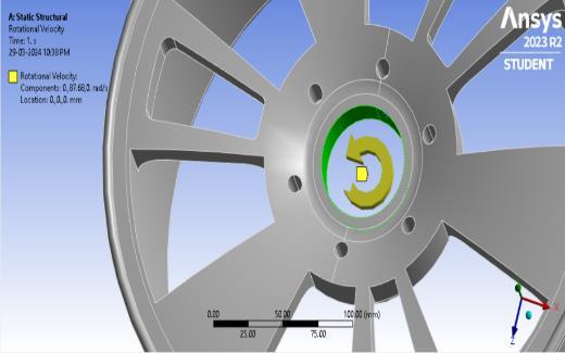
iii. rotationalvelocityisgivenatcentraldriveshaft.
6)ResultsareobtainedbyrunningmodeldesigninSolver environment.
7) Comparison of various Alloys are done to get optimum alloyforwheel.
Followingassumptionsaremadefortheanalysis:
CarWeight–935Kg
PassengerWeight–400Kg(assuming4adults,child)
Luggage–65Kg
CarAccessories–100Kg
TotalWeight–1500Kg
Wheelrimswillexperience1500Kgoftotalweight,which equivalentto14709.97N.
Eachwheelofcarwillbear3677.49NofLoad.
Assumingspeed–60Km/Hr.
Linearvelocity–16.66m/s
Angularvelocity,
W=V/R=16.66/0.19=87.68Rad/s
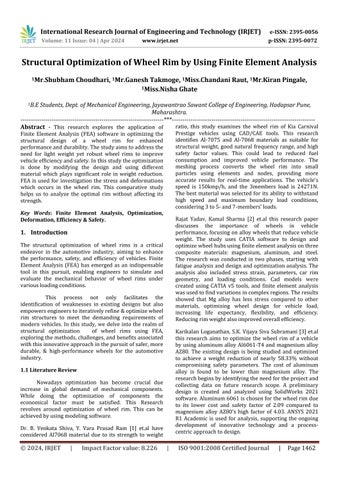
2.2 Rim Nomenclature
2DDiagramofold&newrim,
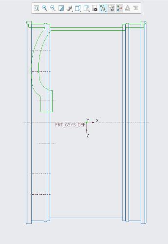
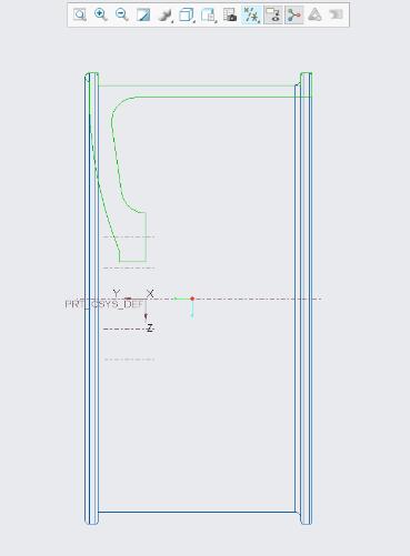
Fig.1 CAD Model of Wheel Rim
Table 1. Dimensions of Wheel Rim
Sr.No Specification OldRim NewRim
2.3 Material Selection
For comparative study following materials were taken.Propertiesofmaterialsarementionedbelow.
International Research Journal of Engineering and Technology (IRJET) e-ISSN: 2395-0056
Volume: 11 Issue: 04 | Apr 2024 www.irjet.net p-ISSN: 2395-0072
Table 2. Properties of Material
Sr.
1
2
3
3. Finite Element Analysis
Themeshingisdoneafter importingthe.igsfile. Thetype ofmeshedelementusedistetrahedronandcoarsemeshis generatedinthecriticalregions.
As The bolts holes and shaft hole will be directly connected rotating shaft, they are considered for fixed supportasshowninimage.Fixedsupportisappliedatsix holesforoldrimandfourholesfornewrim.
The rotational velocity is given at the central axis about which the wheel is going to rotate. The rotating action causescentrifugalforceinthewheelstructure.
The remote force will be applied on external circumference of rim as shown in image. The results are evaluatedbycombingallforcestogether.
3.1 Total Deformation and Stress Results
The stress and deformation for each wheel rim is calculated Figure mentioned below shows the results of aluminumalloyforbotholdandnewrim.
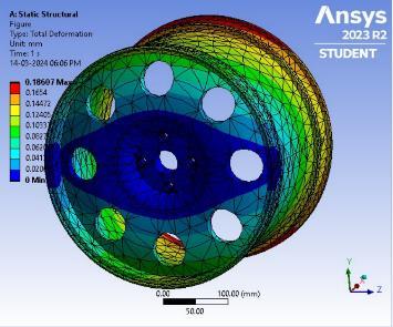
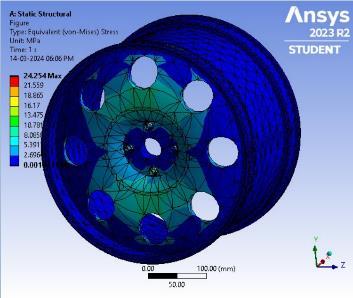
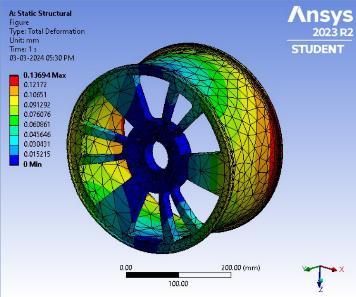
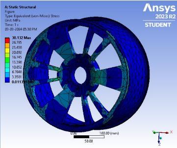
InsimilarmannertheresultsofMgandTitaniumalloyare evaluated.
4. Result Table
Themasscalculationsofwheel rimaredonebasedonthe volumeanddensityofeachmaterial.
Table 3. Properties of Material
International Research Journal of Engineering and Technology (IRJET) e-ISSN: 2395-0056
Volume: 11 Issue: 04 | Apr 2024 www.irjet.net p-ISSN: 2395-0072
Table 4. shows the stress and deformation values evaluatedfromtheanalysis.
Table 4 Result of Stress and Deformation
Property
Al
Here it observed that stresses in old and new rim are nearly same. But when we compare the masses of both rims,theoptimizedrimgivesbetterresults.
4.1 Comparison of results by using chart.
Thefigurebelowshowsthecomparisonofmassesofold rimandoptimizedrim.
Old Rim Mass VS New rim Mass Old Rim New Rim
Old Rim Stress VS New Rim Stress
Old Rim New Rim
AL ALLOY MG ALLOY TITA ALLOY
5. Conclusion
It is possible to reduce not only mass but also manufacturing cost of the wheel without harming its strength (Load Bearing Capacity). With the help of FEA analysis we can predict and understand how wheel rim mightbehaveundervariousphysicalconditions.
1) The mass of old rim reduced after topology optimizationinnewrim.
2) Due to less amount of material as compared to old rim the stress increases in all materials by 4 to 5 MPa. But thesestressesdevelopedarewithinpermissiblerangeand hence new rim with aluminium alloy can gives us the optimumresults.
Furtherworkcanbedoneonmanufacturingofthiswheel rim thatis the mould designand effectoftemperature on themoulddesigned.
1. Aman Sharma, Rajat Yadav, Kunal Sharma, “Optimization & Investigation Of rim For High Performance of Vehicle” , Elsevier, Materials today: Proceeding(45),2021,pp.3601-3604
2. B. Abhiman, M. Yashwant Kumar and M.Vankanta Reddy“OptimizationCarRimUsingDesign&Analysis of Software”, International Journal of Research In Aeronautical And Mechanical Engineering (URAME), Vol.9,Issue8,2021,pp.1-6.
International Research Journal of Engineering and Technology (IRJET) e-ISSN: 2395-0056
Volume: 11 Issue: 04 | Apr 2024 www.irjet.net p-ISSN: 2395-0072
3. Y. Vara Prasad Ram and Dr. Vankanta Shiva “Modelling & Analysis of Rim Using CAE/ CAD Tools”, International Journal of Mechanical Engineering, Vol. 7,2022,pp.1118-1124
4. K.Venkateswara Rao andDr. T.Dharmaraja “Analysis of Wheel Rim Using Finite Element Method”, International Journal of Engineering Research & Technology(IJERT),Vol.03,2014,pp.1259-1263
5. Mr. Sushant. K. Bawane and Prof. Y. L. Yenarkar “Optimization of Car Rim”, International Journal of Engineering Research and Applications (IJERA), ISSN: 2248-9622,Vol.5,Issue10,Part2,2015,pp.01-08.
6. Mr. Chintapalli Shekhar et.al “Design and Structural Analysis of Car Alloy Wheel Using with Various Materials”,International Journal OfAdvanceScientific Research And Engineering Trends (IJASRET), ISSN: 2456-0774,Vol.5,Issue07, 2020, pp.114-120