
International Research Journal of Engineering and Technology (IRJET) e-ISSN: 2395-0056
Volume: 11 Issue: 04 | Apr 2024 www.irjet.net p-ISSN: 2395-0072
International Research Journal of Engineering and Technology (IRJET) e-ISSN: 2395-0056
Volume: 11 Issue: 04 | Apr 2024 www.irjet.net p-ISSN: 2395-0072
Aakash B1 , Aakash Roopan P1 , Abinesh A1, Sivakumar S2
1Student, Department of Mechanical Engineering, Kumaraguru College of Technology, Tamil Nadu, India. 2Assistant Professor II, Department of Mechanical Engineering, Kumaraguru College of Technology, Tamil Nadu, India.
Abstract – The goal of this study is to improve heat transfer in sudden expansion channels (SECs) at various anglesofattack.TheSEC'sexpansionratio(ER)isgiventhe valueof2:1.Ineveryexample,theangleofattack(β)ofVGis adjustedby15degrees,rangingfrom30to90degrees.This study's findings are contrasted with those of a basic rectangular channel (SRC) using a vector gauge (VG). It is assumed that the flow in the range of Reynolds (Re) numbers under investigation is laminar, stable, and incompressible. The analysis reveals that VGs are more successful in boosting heat transfer against pressure decreaseatallanglesofattackinSECthaninSRC.Incontrast tothefrictionfactor,whichremainsunchangedatSECaspect ratios except at higher angles of attack, the rate of heat transfer increases as SEC aspect ratios rise. On the other hand, the friction factor decreases when the VG angle of attack increases. The findings show that the combined influenceoflongitudinalvortexflowandflowseparationis responsiblefortheincreasedheattransferrate.
Key Words: Heat transfer, vortex generator, ramped expansionchannel,rampangle.
Transferringthermalenergyfromonelocationtoanother is known as heat transfer. This is important in modern engineering because devices like gas turbine blades, heat exchangers, microelectronic circuit boards, axial and centrifugal compressor blades, combustors, and heat exchangersareusedtochangetheflowofenergywherever it is needed. Every piece of machinery has a unique heat transferprocedure,sowemustcomprehendhoweachone operates. Vortex generators have been the subject of successfulrecentinventions,studies,andtestingtoimprove theeffectofheattransfer;thesedevicesarecurrentlyinuse, even in real-time. Vortex generators aid in delaying the fluid'sdividedlaminarand turbulentflows.To reducethe impact of the pressure penalty caused by the vortex generator,experimentswithsuddenexpansionchannelflow havebeenconducted.Whencomparedtoconstantareaduct flow, the pressure penalty is lessened due to the vortex generators'minimizationoftheboundarylayer.
Separatedflowsareunpredictable,which makesthemdifficulttocomprehend.Differentgeometries, suchasribs,fences,bluffbodieswithsplitterplates,abruptly expanding pipelines, and cavities, have been used by researcherstobetterunderstandtheseinstabilitiesand,to someextent,reducetheunpredictability.Becauseofitsone fixedseparationpoint,thesuddenexpansionrampedduct provedtobethemostpopularofall.Theflowwakecanbe dividedintothreeprimaryregions:theshearlayerregion, the separation bubble or recirculation zone, and the reattachmentzone.Thesedivisionsarebasedonsignificant flow properties that have been examined by earlier researchers in rapid expansion geometries. The general characteristics of a sudden expansion flow result in the development of a thin boundary layer and an adverse pressuregradient,whichcauseanangularmomentuminthe flow. The turbulent structures inside the boundary layer mergeastheflowcontinuesdownstream,increasingthesize oftheboundarylayer.Thelayerregionis theareawherethe borderlayergrowsandevolves.Low-velocityrecirculationis produced in the space between the shear layer and the nearbywallasaresultofthisflow.Intherecirculationzone, a primary vortex is formed in the centre of the ramped shape,whileasecondaryvortexisformednexttothecorner. Thereattachmentpointisthepointatwhichtheshearlayer eventually bends downward and impinges at a defined locationduetothefluid'sadvantageouspressuregradient. The horizontal distance between the step and the reattachment point is known as the reattachment length. Together,thesethreeareasmakeupthekeycomponentsof a rapid expansion flow, which can be changed or manipulatedtoprovidedesiredresultsincludingimproved mixingqualitiesanddecreasedvibration,noise,anddrag.
Vortexgeneratorsarebasicstructuresresemblingthefin's structure.Thefundamentalpurposeoftheseaerodynamic gadgets is to keep the overflow over the surface to which they are attached. It is a tool that aids in lowering an aircraft's stall speed in aerodynamic terms. The lowest constantflyingspeedatwhichanaircraftcanbecontrolled isknownasthestallspeed.Inordertoattainasafetymargin
International Research Journal of Engineering and Technology (IRJET) e-ISSN: 2395-0056
Volume: 11 Issue: 04 | Apr 2024 www.irjet.net p-ISSN: 2395-0072
betweentheairspeedandstallspeed,vortexgeneratorsare toolsthataidinloweringthestallspeed.Byincreasingflow turbulenceanddecreasingtheformationofboundarylayers, thevortexgeneratorsimproveheattransferefficiency.The creationofboundarylayersinachannelislessenedbythe medium'shighlyturbulentflow.Basedontheirfeaturesand modesofoperation,vortexgeneratorscanbecategorized. Theyareactiveandpassive. Whengeneratorsdrawpower from external sources such as mechanical components, acoustic or electric fields, or surface vibration, they are called active vortex generators. With their special aerodynamicsurfaceshape,passivevortexgeneratorscan producerollingorlongitudinalverticeswithouttheneedfor outsidepowersources.Rectanglewinglets(RW),rectangle wingletpairs(RWP),deltawinglets(DW),anddeltawinglet pair(DWP)aretheoften-utilizedforms.Whenthegeometry isorientedperpendiculartothedirectionofflow,itiscalled awing;whenthevortexgeneratorshavedifferentanglesof attack,itiscalledawinglet.Theimpactofvortexgenerators in the trapezoidal form is being investigated by recent studies. for a static mixer with a high-efficiency vortex (HEV).
There are two different kinds of vortices produced by the vortex generated. We refer to these as longitudinal and
Researchusingsoundmethodologyyieldsdiscoveriesthatare soundscientifically.Thecomprehensiveplanitoffers makes theprocesssimple,effective,andmanageable.Italsohelpsto steer researchers in the right direction. A poorly defined research technique makes it difficult to find reliable and accuratedata,drawmeaningfulconclusions,andcontributeto thebodyofknowledge.
transversevortices.Whilelongitudinalvorticesformwhen theproducedvorticesareinthedirectionofthemedium's flow, transverse vortices act perpendicular to the flow
direction.Becausetheyfunctionbyfirstformingaboundary layeratthevortexgeneratorandthencausingvorticesthat cause a turbulent flow that prevents the formation of a boundary layer in the channel, longitudinal vortices have been found to be more effective than transverse vortices.
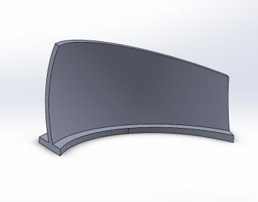
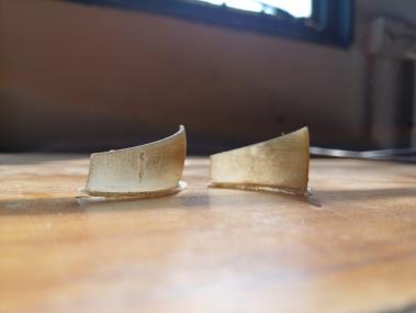
Curvedtrapezoidalwinglets(CTWVGs)arebeingusedinthe experimenttocreatesecondaryflowsinafullyformedflow through a stepflowduct thatfaces backward.Inthe duct, these DWVGs create longitudinal vortices. The impact of single-curveddelta winglets hasbeenstudied extensively, and the results show that they improve the heat transmission effect. Our goal is to comprehend the flow properties and heat transmission with the double-curved deltawingletvortexgenerators(DC-DWVGs).
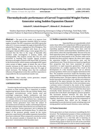
Settingupanexperimentisacrucialstepincarryingout a study. The experiment involves designing the vortex generatorsandthesuddenexpansionrampingflowduct by consulting references from different journals and modifying their specifications according to the needs. The final output varies depending on the stability, capacity, performance, and durability of the materials utilizedintheprocess.
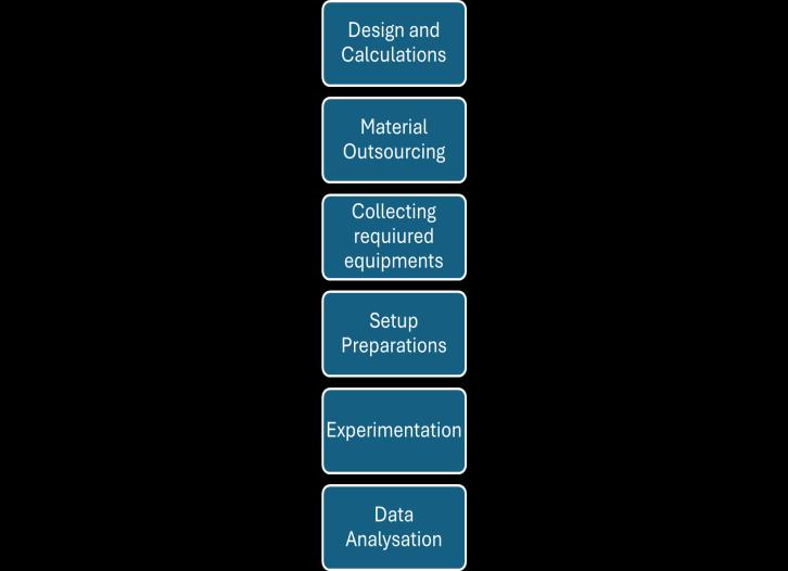
3.1. Sudden Expansion channel dimensions
Comic Section
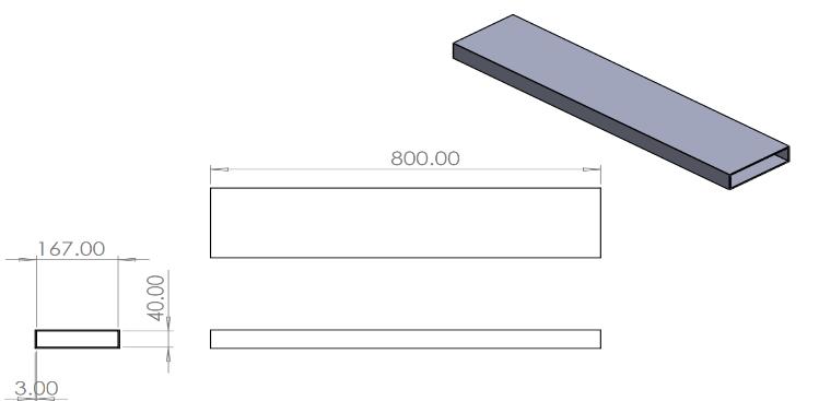
Testing Section
Fig.3 (Alldimensionsareinmm)
3.2. Trapezoidal Vortex Generator Dimensions
The rock-wool insulation bed is positioned at the bottom of the test section, with the heater employed in betweenthecopperplates.Weutilizeanairbloweronthe othersideoftheentrancetochangethedirectionoftheair flow.Variaccontrollersareusedtoregulateboththeheater and the blower's voltage input. Plexi sheet is used to construct the test and comic sections, which are joined to formachannelthatisenclosedonallsidesexcepttheinput andoutflow.Weemploy18"T-type"thermocouples,which are affixed to the copper plate's bottom in a direction parallel to the stream to measure the temperature of the plate.A data acquisition system (DAQ) is then used to measurethereadingsfromthesethermocouplesanddisplay thecorrespondingoutputs.Themassflowrateofairatthe comicsection'sinputismeasuredwithavaneanemometer. Pressuretransducersareusedatthechannel'sentranceand outflowtomeasurethepressuredecrease
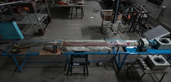
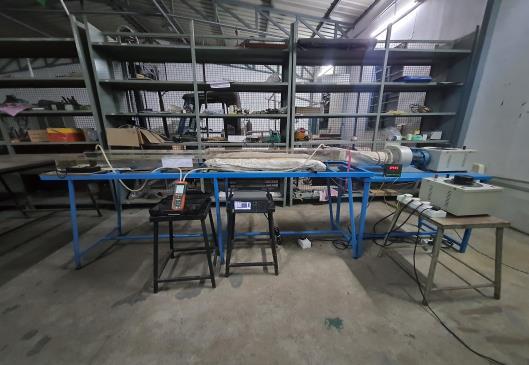
Table. 1. ComponentSpecification
In this experimentation, we position the Curved TrapezoidalVortexGeneratorwiththehigherleadingedgein bothcommonflowupandcommonflowdownconfiguration andobservetheirheattransmissioncapabilitiesbyvarying the velocity of the fluid for different attack angles of the vortexgenerator
International Research Journal of Engineering and Technology (IRJET) e-ISSN: 2395-0056
Volume: 11 Issue: 04 | Apr 2024 www.irjet.net p-ISSN: 2395-0072
Common Flow Up (CFU) configuration of Curved Trapezoidal Vortex Generator – [All angle comparison]
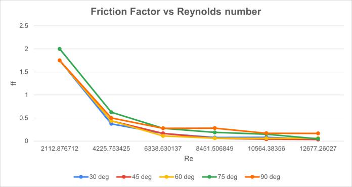
FrictionFactor,f=(2*ΔP*Dh)/(ρ*V2*L)
ReynoldsNumber,Re=(ρ*V*Dh)/µ
Therelationshowsthatthefrictionfactordecreases as the velocity of the fluid increases and the Reynolds number increases as the velocity of the fluidincreases
Nusseltnumber,Nu=(h*Dh)/k
ReynoldsNumber,Re=(ρ*V*Dh)/µ
The Nusselt number is the function of Reynolds numberraisedtothecertainpoweralongwiththe Prandtlnumber.
Laminar External flow, Nu ≈ 0.664 * (Re^0.5) * (Pr^0.33)
Turbulent External flow, Nu ≈ 0.037 * (Re^0.8) * (Pr^0.3)
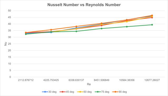
Boththeabovegraphs, (Fig.8.) and (Fig.9.) impliesthat the attack angle 900 shows the better thermohydraulic performance factor with greater heat transmission rate comparedtoallotherattackanglesbeingpositionedinthe commonflowupconfiguration.
Common Flow Down (CFD) configuration of Curved Delta Vortex Generator – [All angle comparison]
Analyzingthecommonflowdownperformance oftheCurvedTrapezoidalVortexGeneratorintheramped expansionchannelresultedinthefollowingoutcomes.
Boththeabovegraphs, (Fig.10.) and (Fig.11.) implythat different attack angles show better thermohydraulic performancefactorswithgreaterheattransmissionratesat differentReynoldsnumbersbeingpositionedinthecommon flow-downconfiguration
International Research Journal of Engineering and Technology (IRJET) e-ISSN: 2395-0056
Volume: 11 Issue: 04 | Apr 2024 www.irjet.net p-ISSN: 2395-0072
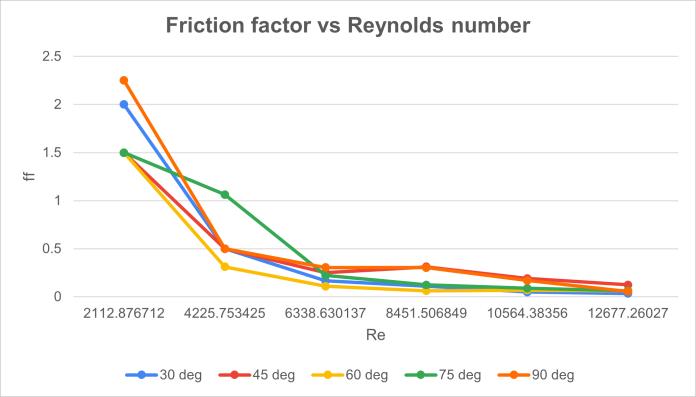
Thesameexperimentisrepeatedwiththelowerleadingedge andthegraphsobtainedareasfollows:
Common Flow Up (CFU) configuration of Curved Trapezoidal Vortex Generator – [All angle comparison]
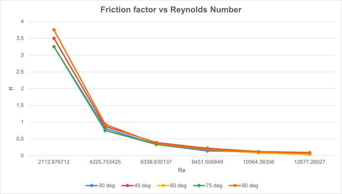
Fig. 12 FrictionfactorvsReynoldsNumber
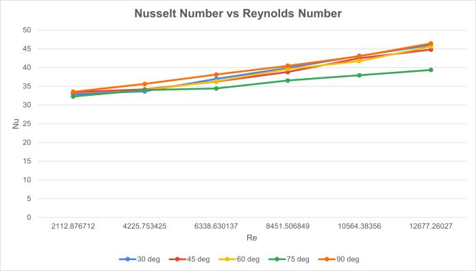
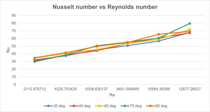
Fig. 13. NusseltNumbervsReynoldsNumber
Common Flow Down (CFD) configuration of Curved Delta Vortex Generator – [All angle comparison]
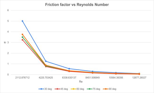
Fig. 14. FrictionFactorvsReynoldsNumber
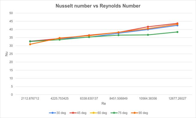
Fig. 15. NusseltnumbervsReynoldsnumber
From the above graphs, (Fig.12, 13, 14 and 15) implies that the attack angle 900 shows the better thermohydraulic performance factor with greater heat transmissionratecomparedtoallotherattackanglesbeing positionedinthecommonflowupandcommonflowdown configuration.
Hydrothermalcharacteristicsofthesudden expansion duct are thus analyzed. The heat transfer enhancement can be seen when the vortex generator is placedat90degreesintheflowdirection,nomatterwhat theconfiguration.Theobserveddifferencesaresignificant andthatplaysanimportantroleinfurtherimprovisationsin sudden expansion ducts, ramped expansion, and other channelsinvolvedinheattransferring.
Wewholeheartedlythankour Chairman Dr.B. K Krishnaraj Vanavarayar, our Correspondent Thiru M.Balasubramanium, our Joint Correspondent Thiru Shankar Vanavarayar, our advisor Dr V Manivel muralidaran for providing us with the required infrastructure at Kumaraguru College of Technology. We express our gratitude to our beloved Principal Dr. D. Saravanan, for his invaluable support, motivation, and guidance,andalsoforprovidingusallthenecessaryfacilities required for carrying out this project work We are very gratefultoourrespectedHeadoftheDepartment,Mechanical Engineering, Dr. C. Velmurugan for his constant and continuousmotivation,review,andcooperationthroughout thisprojectwork.Wewishtorecordourprofoundhappiness and gratitude to our Project Coordinator Dr. K. M. Senthilkumar, DR. K. Krishnamoorthi, DR. S. Sivakumar andProjectGuide Mr. S. Sivakumar fortheirconstantand continuouseffort,guidance, andvaluabletime.Oursincere and hearty thanks to all the faculty members and staff of MechanicalEngineering Department for their well wishes, timelyhelpandsupportrenderedtous fordoingthisfinal
International Research Journal of Engineering and Technology (IRJET) e-ISSN: 2395-0056
Volume: 11 Issue: 04 | Apr 2024 www.irjet.net p-ISSN: 2395-0072
yeardesignandfabricationprojectwork.Weareverygreatly indebtedtoourfamily,relativesandourallfriendswithout whomourlifewouldnothavebeenshapedtothislevel.
[1] Esmaeilzadeh,N Amanifard,andH.M Deylami,“In ordertomaximizeflowcharacteristicsandenhance heattransferina heat exchanger,a comparisonof straightandcurvedtrapezoidallongitudinalvortex generators wasconducted,” Appl. Therm Eng ,vol 125,pp.1414–1425,2017.
[2] Armaly, B., Durst, F., Pereira, J., & Schönung, B Experimental and theoretical investigation of backward-facing step flow. Journal of Fluid Mechanics, 127, 473-496. doi:10.1017/S0022112083002839
[3] W Hu,L Wang,Y Guan,andW Hu,“Theimpactof winglet vortex generator shape on a circular tube bank fin heat exchanger's thermal-hydrodynamic performance,” Heat Mass Transf. und Stoffuebertragung, vol 53, no. 9, pp 2961–2973, 2017.
[4] M.F.MdSalleh,H.A.Mohammed,andM.A.Wahid, “Thermal and hydraulic characteristics of trapezoidal winglet across fin-and-tube heat exchanger(FTHE),” Appl. Therm. Eng.,vol.149,no. November2018,pp.1379–1393,2019.
[5] S. K. Sarangi, D. P. Mishra, H. Ramachandran, N Anand, V. Masih, and L S. Brar, “Examining and refining the small heat exchanger's curved trapezoidal winglet geometry,” Appl. Therm Eng , vol 182,no.September2020,p.116088,2021.
[6] J Carpio and A Valencia, “Enhancement of heat transferusinglongitudinalvortexgeneratorsinflattubecompactheatexchangers,” Int. Commun. Heat Mass Transf.,vol 120,no.xxxx,p.105035,2021
[7] Tsay,YL.,Chang,T.&Cheng,J.Enhancementofheat transferforbackward-facingstepflowinachannel with the placement of baffles on the channel wall Acta Mechanica 174, 63–76 (2005) https://doi.org/10.1007/s00707-004-0147-5
[8] Abbott,D.E.,andKline,S.J (September1,1962) " ExaminingSubsonicTurbulentFlowThroughSingle andDoubleBackwardFacingStepsExperimentally" ASME J. Basic Eng September 1962; 84(3): 317–325.https://doi.org/10.1115/1.3657313
[9] Kanna,P.R.,andDas,M.K.(January25,2006)."A two-dimensional Laminar Inflexible Wall Jet Flow Under Backward-Facing Step: A Numerical
Simulation." ASME. J. Fluids Eng. September 2006; 128(5): 1023–1035.https://doi.org/10.1115/1.2243298