
International Research Journal of Engineering and Technology (IRJET) e-ISSN: 2395-0056
Volume: 11 Issue: 04 | Apr 2024 www.irjet.net p-ISSN: 2395-0072
International Research Journal of Engineering and Technology (IRJET) e-ISSN: 2395-0056
Volume: 11 Issue: 04 | Apr 2024 www.irjet.net p-ISSN: 2395-0072
Prasenkumar Saklecha1 , Swati Bhangale2 , Prajakta Shete3, Rameshwari Ghate4, Juhi Raut5 , Jay Mhatre 6 ,
1Head of Department , Department of Civil Engineering, New Horizon Institute of Technology and Management, Maharashtra, India
2Asst. Professor , Department of Civil Engineering, New Horizon Institute of Technology and Management, Maharashtra, India
3B.E student, Department of Civil Engineering, New Horizon Institute of Technology and Management, Maharashtra, India
4B.E student, Department of Civil Engineering, New Horizon Institute of Technology and Management, Maharashtra, India
5B.E student, Department of Civil Engineering, New Horizon Institute of Technology and Management, Maharashtra, India
6B.E student, Department of Civil Engineering, New Horizon Institute of Technology and Management, Maharashtra, India
Abstract -
To ensure the safety of a building, it is imperative to have a geotechnical or soil investigation report that explains the specifics of the underlying soil. It provides a comprehensive understanding of soil properties and how they respond to different situations. Standards and guidelines for conducting soil investigations are in place in India, however there is no legislation dictating whether or not a soil report must be produced. This study is to raise awareness of the current local government administrative building construction system as well as the degree of knowledge about soil investigation and itsnecessityamonga fewlocalcontractors.An interviewwith the local government, a survey of a small number of contractors, and some recommendations, such as concentrating more on.
1.1 Geotechnical/ soil investigation
Prior to construction, a soil study, also known as geotechnical work, is conducted to better understand the soil. It is a collection of techniques for analyzing and comprehendingthesubsurfaceprofile,sitecircumstances, andsoilcharacteristics.Onewaytoanalyzethestateofthe soilanddeterminethenecessaryfoundationisthroughsoil testing,whichisdoneaspartofthegeotechnicalresearch. Intherealmofconstruction,soilanalysisandclassification are carried out to assess the soil's bearing capacity to a particular degree (IS 1498, 1970). Soil study has several applications, such as reducing uncertainty in foundation design,determiningsettlement,evaluatingstability,andso forth.
1.2 Methods of Soil Investigation
1. BoreholeLogging
2. Soilsampling
3. StandardPenetrationTest
4. BearingcapacityandSafebearingcapacity
5. Settlementpressure
6. Designofshallowfoundation
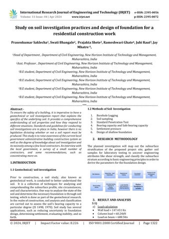
The planned investigation will map out the subsurface stratification of the proposed project site, gather soil samples for laboratory testing to uncover engineering attributes like shear strength, and classify the subsurface stratumaccordingtobasicengineeringprinciplesinorderto derivetheparametersforthefoundationdesign.
3.1) a) Loadcalculation
Wallload=147.451Kn
Columnload=60.24kN
International Research Journal of Engineering and Technology (IRJET) e-ISSN: 2395-0056
Volume: 11 Issue: 04 | Apr 2024 www.irjet.net p-ISSN: 2395-0072
Totalslabload=450Kn
Totalloadononecolumn=1351.201Kn
Totalloadonfoundation=51355.638Kn
b) Calculation of bearing capacity(qnu), safe bearing capacity(qns)andsettlement
c) DesignofShallowFoundation
Tofind-sizeoffooting
Step1-Loadonfooting
Loadonfooting(Wf)=1486K
FactoredLoadonfooting(Wu)=2229Kn
Step2-Areaoffooting
Areaoffooting(Af)=6m2
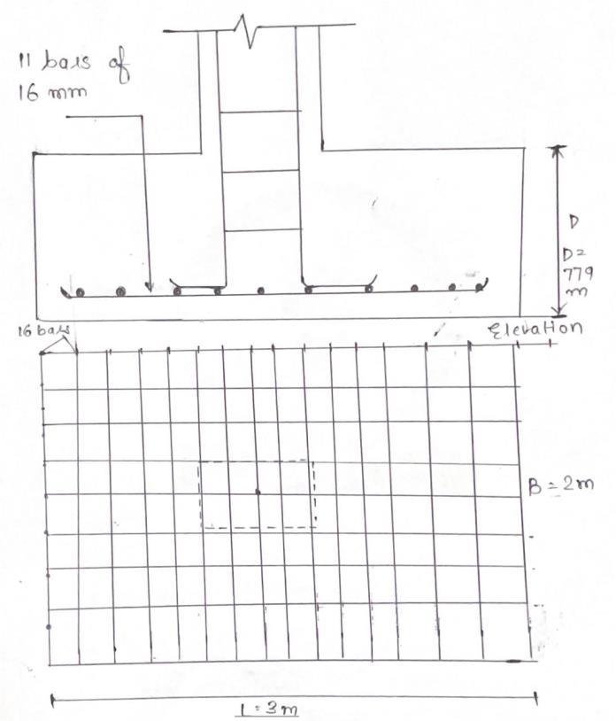
Step3-Sizeoffooting
L=3.0m,B=2.0m
Step4-Upwardsoilpressure
P=338kN/m2
Step5-Depthoffootingforbendingmoment
Criticalsectionforbendingmomentcriteriais
Consideredonthefaceofthecolumn
Mx=571.22kN.m
My=397.1kN.m
Maximumbendingmoment
Mmax=571.22kN.m
Limitingmomentofresistance
Mulim =0.138fcdbd2
d=719.3mm
Overalldepth(D)=779mm
Effectivedepth(d)=719mm
Step6–checkfordepthinonewayshear(beamshear)
Shearforceatcriticalsection
Vu= 676(1.3-d)
Ks=1
τc=1.12
τv=1120kN/m2
d=0.301m
d=301mm<719mm
Therefore,depthoffootingprovidedissafeinonewayshear
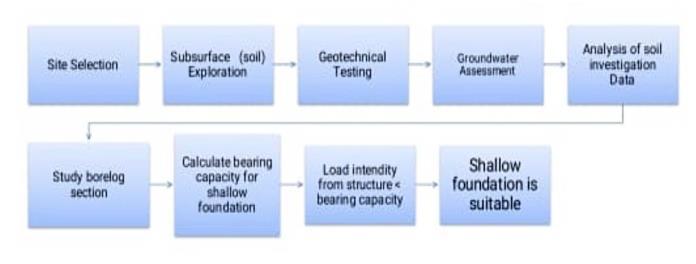
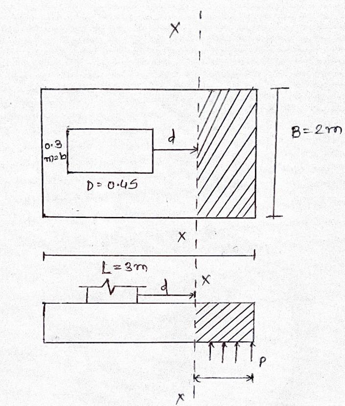
Step7-checkfordepthintwowayshear (punchingshear)
Criticalsectionfortwowayshearisconsideredatdistance d/2fromtheperipheryofthecolumnface
International Research Journal of Engineering and Technology (IRJET) e-ISSN: 2395-0056
Volume: 11 Issue: 04 | Apr 2024 www.irjet.net p-ISSN: 2395-0072
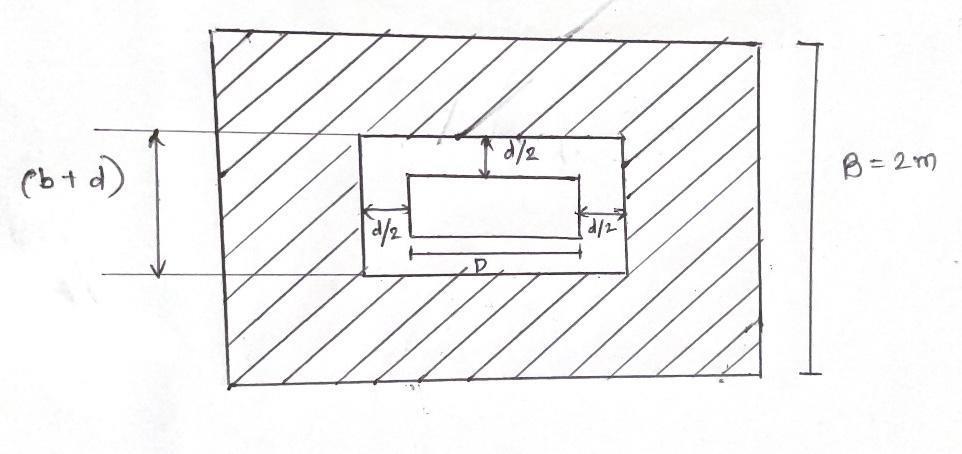
fig no. 3.1.2 shear resistance by concrete
Vu=upliftpressurexshadedarea
=p[BL–(b+d)(D+d)]
=338[2x3-(0.23+d)(0.4+d)]…..(iii)
Shearresistancebyconcrete
Vu =τcbod
=1.26+4d……(iv)
Equating(iii)and(iv)
d=0.33m<0.719m therefore,safeintwowayshear
Step8-
Reinforcement(Mu)=571.22kN/m
Astx=1406.19mm2
Numberofbarsfor16mmbars
Areaofonebar=201mm2
n=12bars
provide12barsof16mmalonglongdirection tofindinshortdirection–Mu=397.1kN.m
Asty=2169.07mm2
Areaofonebar=201mm2
n=11bars
provide11barsof16mmalongshortdirection
3.2) Footing analysis in STADDPRO
1) Nodeformation.
2) Assigning the node's fix support and creating support.
3) To load a primary load, select "dead load" as the loadingtypeandaddaloadscenario.
4) Addthenodalloadinthefydirectiontoget1351.20 KN.
5) Select the load 1351.201 and then attach it to the newlyconstructednode.AfterapplyingUDLtothe portalframe,wehadaresultof1351.201KN.
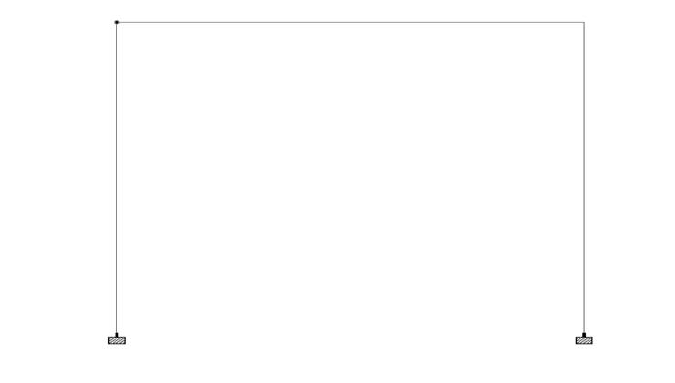
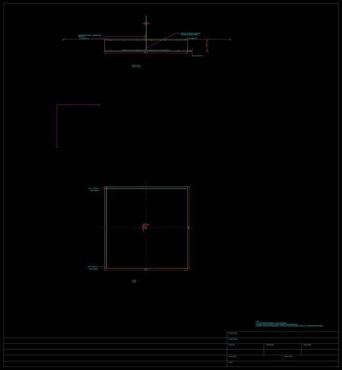
no. 3.2.1 Model of frame
International Research Journal of Engineering and Technology (IRJET) e-ISSN: 2395-0056
Volume: 11 Issue: 04 | Apr 2024 www.irjet.net p-ISSN: 2395-0072
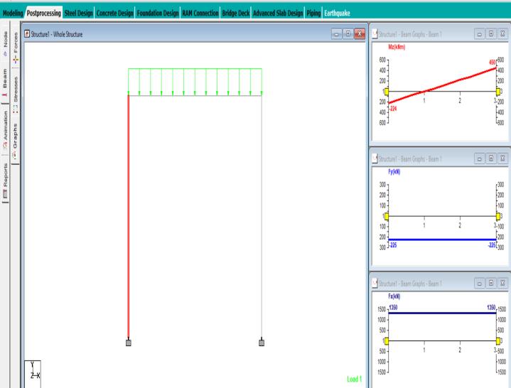
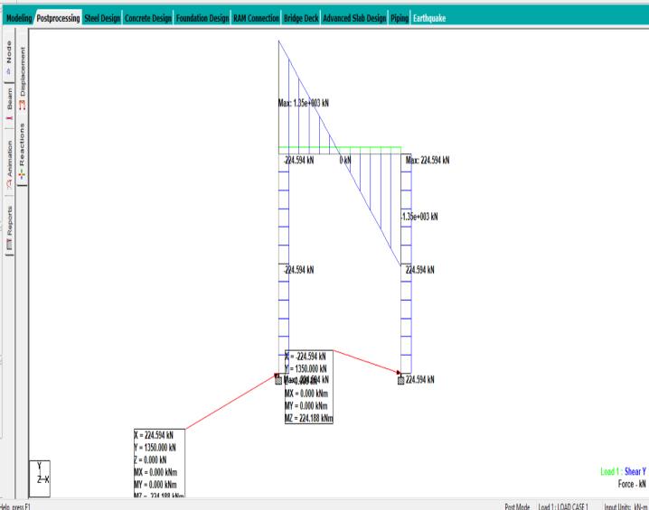
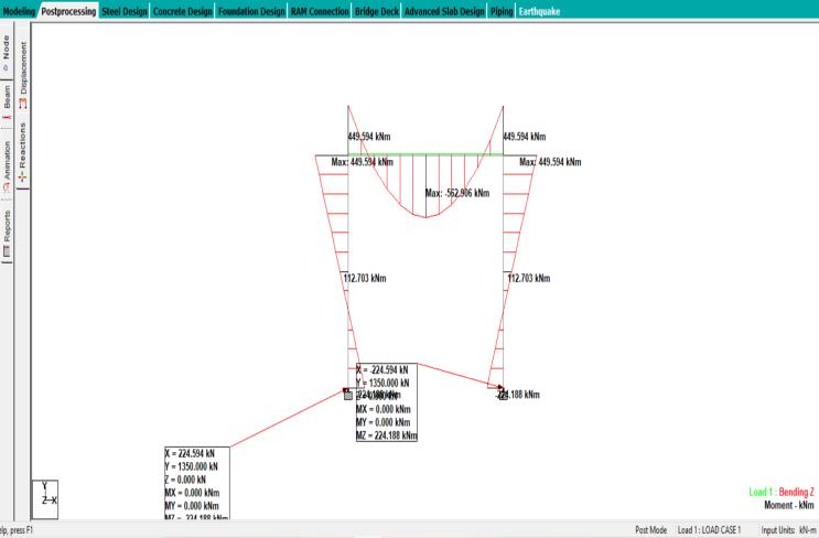
Aftercarefullycalculatingtheresultsmanuallyaswellason STADDPROwehavegotequalresultswhichis1351.201KN. The study on soil investigation practices and design of foundationsforresidentialconstructionworklikelyaimsto understand the correlation between soil characteristics, foundation design, and construction outcomes. It may involve evaluating various soil testing methods, analyzing soilproperties,andproposingoptimizedfoundationdesigns to ensure structural integrity and stability for residential buildings.The resultscouldinformbestpracticesfor engineers and builders to follow during the planning and constructionphases.
Themainconclusionsandconsequencesof astudyonsoil investigation techniques and foundation design for residentialconstructionworkareusuallysummedupinthe study'sconclusion.Itmayconsistof:
1.Thesignificanceofconductingacompletesoilresearchto ascertainthecharacteristicsofthesoil,itsbearingcapacity, andanypossiblehazardssuchslopeinstabilityorsettling.
2.Theimportanceofselectingafoundationdesignthattakes intoaccountlocalcodes,buildingloads,andsoilconditions.
3.Thedemandforcollaborationbetweenstructural,soil,and architecturalexpertstoguaranteethatthefoundationdesign satisfiesperformanceandsafetystandards.
International Research Journal of Engineering and Technology (IRJET) e-ISSN: 2395-0056
Volume: 11 Issue: 04 | Apr 2024 www.irjet.net p-ISSN: 2395-0072
4. Suggestions for additional study or advancements in methodsofsoilanalysisorfoundationdesign.
1. Foundation Analysis and Design, J.E. Bowles, McGrawHillPublication,5thEdition1996
2. CanadianFoundationEngineeringManual.
3. SoilMechanicsinEngineeringPractice,2ndEdition, Terzaghi K. and Peck R. B., John Willey and Sons, 1967.
4. FoundationDesignManual,N.V.Nayak,5thEdition, 1996.
5. IS:6403-1981, Code of Practice for Design and ConstructionofShallowFoundationsonSoils
6. IS 12070: 1987, Code of Practice for Design and ConstructionofShallowFoundationsonRock