
International Research Journal of Engineering and Technology (IRJET) e-ISSN: 2395-0056
Volume: 11 Issue: 04 | Apr 2024 www.irjet.net p-ISSN: 2395-0072
International Research Journal of Engineering and Technology (IRJET) e-ISSN: 2395-0056
Volume: 11 Issue: 04 | Apr 2024 www.irjet.net p-ISSN: 2395-0072
Ayushi Vinodia1 , Kanchan Cecil2
1Student Department of Electronics and Telecommunication,Jabalpur Engineering College,482011,Jabalpur M.P India.
2Professor of Electronics and Telecommunication Department,Jabalpur Engineering College,482011,Jabalpur M.P,India.
Abstract – This research simulates a new flexible antenna design using CST Software 2019. The innovative aspect introduced in this study involves placing a polyethylene substrate in front of the flexible antenna that was originally designed on a textile substrate. This addition serves the purpose of safeguarding the flexible antenna from environmental factors, especially during rainy conditions. When the antenna gets wet, it changes its properties and characteristics, primarily due to alterations in the dielectric constant. As a result, the polyethylene substrate is applied to prevent moistureabsorption. Theresearchpresentssimulation results, including data on return loss, radiation patterns, and axial ratio in both 2-D and 3-D formats. This research introduces an innovative design for a flexible antenna array intended for wireless applications. The antenna is simulated with CST software and is specifically aimed at creating a body area network operating at a single frequency band of 12.3 GHz. The substrate material for the antenna is denim jeans, with a dielectric constant of 1.7. It is covered with a layer of polyethylene substrate, which has a dielectric constantof2.25 and incorporates a conductive element made from copper tape. The physical dimensions of the antenna board are60x40 mm. The designed antenna offers a relatively wide bandwidth of 44.8%, spanning the frequency range from 12GHz to 12.55GHz, making it suitable for the intended purpose. This kind of bandwidth is considered optimal for this antenna. The proposed single-band antenna design is versatile and wellsuited for use in multiband applications and wearable devices within wireless bodyareanetworks(WBANs).It'simportantto note that antennas featuring multiple identical patches are commonly referred to as array antennae.
Key Words: Polyethylenesubstrate,Singleband,Wearable antennasoftware.
Bothcompaniesandresearchershavebeenmoreinterested in flexible technologies in the last several years. This research area has become a top priority for many public researchagencies.Aswedevelopflexibleelectronicsystems, it'scrucialtoincludeantennasthatcanworkwithinspecific frequencyranges.Thisisbecausethere'sahighdemandfor
wirelessconnectivityinourdata-drivensocietytoday,and theseantennashelpmakeitallpossible[1-4].
Theperformanceofthesesystemsprimarilyhingesonthe quality of the integrated antenna. Flexible wireless technologiescallfortheinclusionofadaptable,lightweight, compactantennaswithalowprofile.Atthesametime,these antennasshouldbehighlyefficient,effectivewithreasonably broad bandwidth, and exhibit favorable radiation characteristics,asindicatedinreferences[5-11].
In this research, a 2-diamond shape with a 2-L cut shape flexibleantennawhichisanarrayantennadesignedonthe materialhavingadielectricconstantof1.7knownasJeans covered with polyethylene substrate that has a dielectric constantof2.25andsavestheantennafromaging-relatedlosses.
An array antenna that consists of two or more identical patches refers to a configuration where multiple antenna elements, typically of the same size and shape, are placed near form a collective antenna system. These identical patches work together to achieve specific radiation characteristicsandbeamformingcapabilities.Whenmultiple patches are used in an array, they can be individually controlled in terms of phase and amplitude to create desirableradiationpatterns,suchassteeringthemainlobein a particular direction or improving signal reception and transmission in specific areas. The coordination and manipulation of these identical patches enable the array antenna to exhibit enhanced performance, directivity, and gain for various applications, including in wireless communicationsystemsandradarsystems.
Antennasdesignedforwearingarecommonlyreferredtoas wearables.These wearable antennasfind extensiveuse in applications like biomedical RF systems and wearable wirelesscommunication.Theyareparticularlyvaluablein wirelessbodyarea networks(WBANs),whereanantenna plays a pivotal role in enabling wireless communication,
International Research Journal of Engineering and Technology (IRJET) e-ISSN: 2395-0056
Volume: 11 Issue: 04 | Apr 2024 www.irjet.net p-ISSN: 2395-0072
encompassing off-body, on-body, and even in-body connectivity. Wearable antennas have a wide range of applications across diverse sectors, including health monitoring, entertainment, business, security, military defense, and many other fields [12]. Fig.1. illustrates wearable technologies and their uses. Wearable antennas are constructed from a variety of conductive as well as dielectric materials. Such materials are wisely selected to allow for reasonable mechanical deformations (such as twisting,wrapping,andbending)withminimalimpactunder variousweatherconditions(ice,snow,rain,etc.),whilealso providing effective electromagnetic radiation protection. More recently, alternative materials, both fabric and nonfabric, have been utilized in the development of wearable antennas. When using fabric materials, it is crucial to accuratelycharacterizethepropertiesofthesetextiles[13]. On the other hand, non-fabric flexible polymer-based materialslikePET(Polyethyleneterephthalate),Kapton,and PEN(Polyethylenenaphthalate)substratesofferconsistent andstabledielectriccharacteristics[14].
2. Dielectric Constant
JeansMaterial:Denim,orjeans,hasadielectricconstantof 1.7.
PolyethyleneMaterial:Polyethylenehasadielectricconstant of2.25.
Table -1: Simulationofa2
shapewith
cut shapeantenna. This table represents the previous work and proposed work
1. Dielectric Permittivity. 1.7(Jeans Material) 2.25 (Polyethylen esubstrate) 1.7(Jeans Material)
8. The thicknessof theground. 0.0038 0.0038.
9. LossTangent 0.0028(Jeans Material) 0.0028 (Jeans Material)
0.0005 (Polyethylen esubstrate).
Resonant Frequencies: 12.3GHz
Bandwidth Calculation: SingleBand
F1=12GHz
F2=12.55GHz
Bandwidth=(F2–F1)/[(F1+F2)/2]
Bandwidth=44.80%


The layout of the flexible antenna we've introduced is shieldedwithpolyethylene.Thisservesthedualpurposeof safeguarding the flexible antenna from moisture. Subsequently, a comparison of the results is conducted to readily discern the benefits of employing a polyethylene substrate
A new concept was introduced for creating a flexible antenna enclosed in polyethylene and made using denim material.Thisinnovativeantennafeaturesagroundsizeof 60x40mmandoperatesataresonancefrequencyof12.3GHz. The overall outcomes have been enhanced and verified throughdesignusingCST(ComputerSimulationTechnology) software.Additionally,theantennahasbeendesignedwitha polyethylene covering to protect it from environmental factorslikemoistureanddirt.Withthepolyethylenecover, theantennaresonatesat12.3GHz.
International Research Journal of Engineering and Technology (IRJET) e-ISSN: 2395-0056
Volume: 11 Issue: 04 | Apr 2024 www.irjet.net p-ISSN: 2395-0072
4. Comparison Between Previous Design And Proposed Design
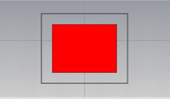
Figure-2: Front view of proposed design covered with polyethylenesubstrate(Dielectricconstant=2.25).

ReverseViewoftheproposeddesign.
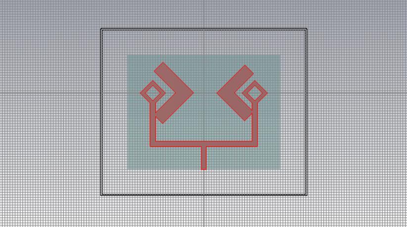
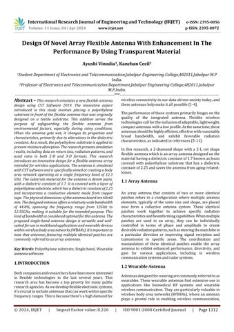
Figure-4: 2-diamond-shaped2-cutantennawithdielectric constant=1.7(JeansMaterial)
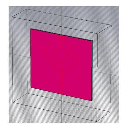
Figure-5: PreviousDesignwithpolyethylenesubstrate.
5. Result and Analysis
According to the research provided in this article, the flexibleantennaonthefrontsideoftheantennaisshielded from water by a unique transparent substance called polyethylene.Polyethylenehasadielectricconstantof2.25. Thethree-dimensionalperspectiveofaflexiblepolyethylenecovered antenna is shown in Figure 2.2. The different propertiesofpolyethylenematerialareshowninTable3.
SParameter.
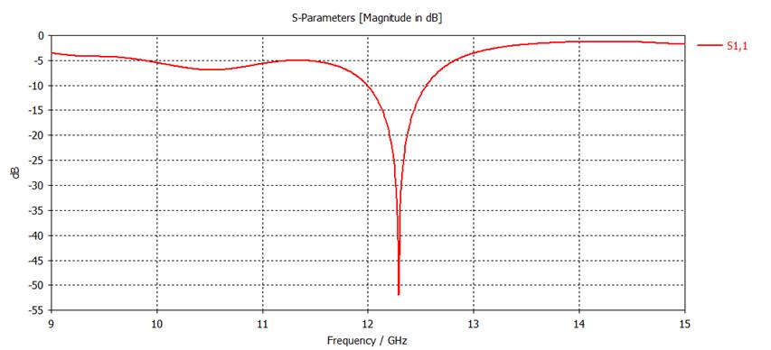
:SParameter.
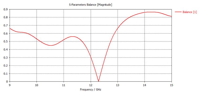
Figure-7: SBalanceParameter.
International Research Journal of Engineering and Technology (IRJET) e-ISSN: 2395-0056
Volume: 11 Issue: 04 | Apr 2024 www.irjet.net p-ISSN: 2395-0072
SParameter-TheS-parameterreferstohowwellacircuitcan handle signals coming in and going out. It quantifies how muchofthesignalisreflectedduetothemismatchbetween thecircuit'sinputandtheconnecteddevice'simpedance. RadiationPattern.
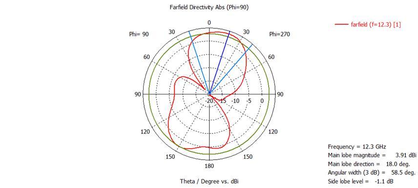
Figure-8: PolarRadiationPatternat12.3GHz.
Thesuggestedantennaprovidesavisualrepresentationofits radiation pattern through a polar plot at the resonant frequency of 12.3GHz. Additionally, in Figure 9, we can observe the 2-D Cartesian radiation patterns at the same frequency. Furthermore, both Figure 10 and Figure 11 display the 2-D & 3-D radiation patterns at the antenna's resonant frequency of 12.3GHz. These radiation patterns reveal important characteristics, such as the main lobe's orientationat18.0degrees,anangularwidthof58.5degrees (3dB),andamainlobemagnitudeof3.15dBiatφ=90o.At thisresonantfrequencyof12.3GHz,theradiationefficacyis approximately0.007867dB,whilethedirectivitymeasures 3.004dBi.
PolarRadiationPattern-Anantenna'spolarradiationpattern is a pictorial depiction of the ways in which it emits or receives electromagnetic energy in relation to its physical orientation. This pattern is typically displayed in a polar coordinate system with the antenna at the center. It illustrates how the antenna's performance varies with azimuth (horizontal) and elevation (vertical) angles. By examiningthepolarradiationpattern,onecanunderstand the antenna's coverage, gain, and directivity, providing insights into its suitability for different applications. For example,adirectionalantennawillhaveapolarpatternthat concentrates energy in a specific direction, while an omnidirectional antenna will have a more uniform distributionofenergyinalldirections.
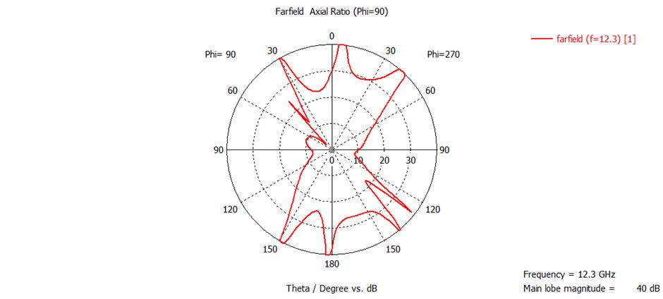
AxialRatioPolarForm-Theaxialratioisreferredtotheratio ofthemajoraxistotheminoraxisofanantenna'scircularly polarizedradiationpattern.Inotherwords,itquantifieshow stretchedorcompressedtheellipticalshapeoftheantenna's polarization pattern is, providing information about the deviationfromperfectcircularpolarization
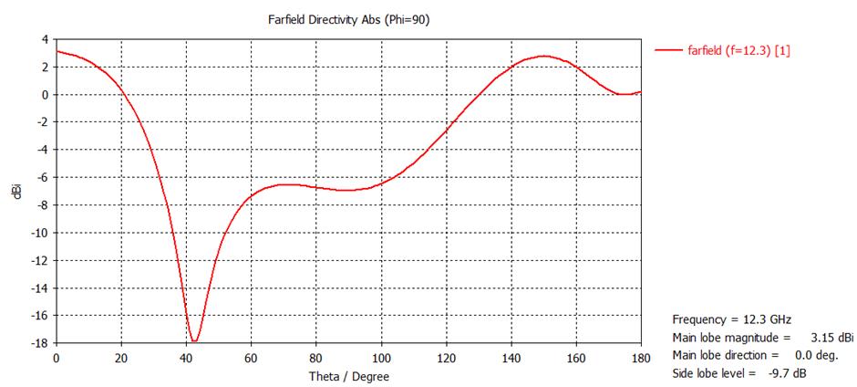
2D Cartesian Radiation Pattern-A 2D Cartesian radiation pattern of an antenna is a pictorial depiction that displays howtheantennaradiatesorreceiveselectromagneticenergy in a two-dimensional plane, usually the horizontal plane (azimuth). It provides a visual map of the antenna's performance,showingthestrengthanddirectionofradiation or reception at different azimuth angles, typically representedonarectangulargrid.Thisrepresentationallows engineersanddesignerstoassesstheantenna'scoverageand gaininthehorizontalplane,providingessentialinsightsinto itsdirectionalcharacteristicswithoutconsideringthevertical dimension.
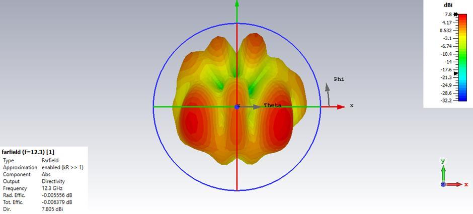
3DCartesianRadiationPattern-The3DCartesianradiation patternofanantennaisapictorialdepictionthatillustrates howtheantennaradiatesorreceiveselectromagneticenergy inthree-dimensionalspace.Itdescribeshowtheantenna's performancevariesacrossdifferentdirections,notjustina
International Research Journal of Engineering and Technology (IRJET) e-ISSN: 2395-0056
Volume: 11 Issue: 04 | Apr 2024 www.irjet.net p-ISSN: 2395-0072
flat plane. The pattern is typically presented as a threedimensionalplot,wheretheantenna'sradiationpropertiess are shown in terms of azimuth (horizontal direction), elevation (vertical direction), and radial distance from the antenna.Thisrepresentationprovidesacomprehensiveview ofhowtheantenna'senergyisdistributedinalldirections aroundit,offeringvaluableinformationforantennadesign andanalysis.
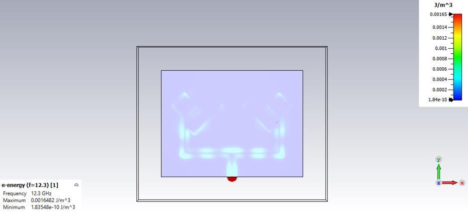
Figure-12: E-energydensityat12.3GHz.
E-energydensity:TheE-fieldenergydensityofanantennais ameasureoftheelectromagneticenergystoredintheelectric fieldsurroundingtheantenna.Itquantifiestheconcentration of energy within the electric field components of the electromagneticwaveradiatedorreceivedbytheantenna. Thisenergydensityprovidesinsightsintothedistributionof energywithintheelectromagneticfieldandcanbeusefulfor understanding the antenna's radiation characteristics and interactionswithitssurroundings.
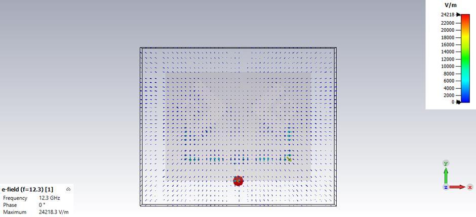
Figure-13: E-Fieldat12.3GHz.
E-Field:TheE-field(electricfield)ofanantennareferstothe electriccomponentoftheelectromagneticfieldgeneratedby theantennawhenitradiatesorreceivessignals.Itrepresents the strength and direction of the electric field at various points in the space surrounding the antenna. The E-field, along with the H-field (magnetic field), constitutes the completeelectromagneticwave.UnderstandingtheE-fieldis crucialforassessingtheradiationpropertiesoftheantenna and how it interacts with other objects or antennas in its vicinity.
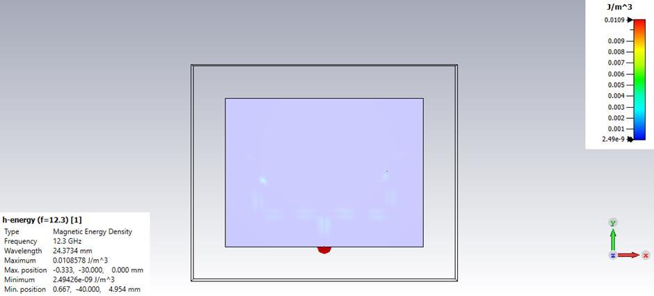
Figure-14:Henergydensityat12.3GHz.
H-energy density: The H-field energy density of an antennaisameasureoftheelectromagneticenergystoredin themagneticfieldsurroundingtheantenna.Itquantifiesthe concentration of energy within the magnetic field components of the electromagnetic wave radiated or received by the antenna. This energy density provides insights into the distribution of energy within the electromagneticfieldandcanbeusefulforunderstandingthe antenna'sradiationcharacteristicsandinteractionswithits surroundings.
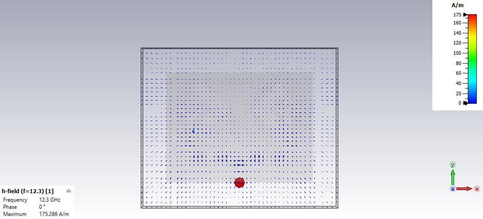
Hfieldat12.3GHz.
Hfield:TheH-field(magneticfieldintensity)ofanantenna referstothemagneticcomponentoftheelectromagneticfield producedbytheantennawhenitradiatesorreceivessignals. Itcharacterizes thestrengthanddirectionof the magnetic fieldatvariouspointsinthespacesurroundingtheantenna.
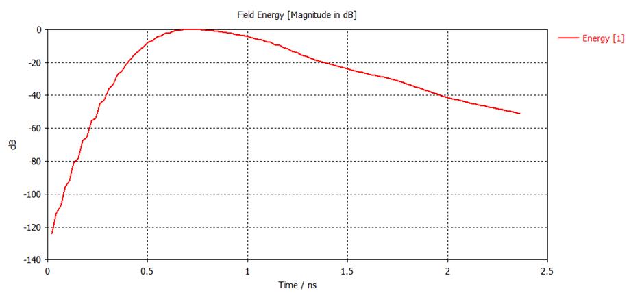
Figure-16: ExcitationEnergy.
International Research Journal of Engineering and Technology (IRJET) e-ISSN: 2395-0056
Volume: 11 Issue: 04 | Apr 2024 www.irjet.net p-ISSN: 2395-0072
Energy excitation of an antenna refers to the process of supplying electrical power to the antenna so that it can efficientlytransmitorreceiveelectromagnetic waves.This electricalenergyisconvertedintoelectromagneticradiation during transmission or into electrical signals during reception, enabling the antenna to perform its intended communication function. How the energy is applied to the antenna, including its frequency, voltage, and phase, can impacttheantenna'sperformanceandcharacteristics.on.
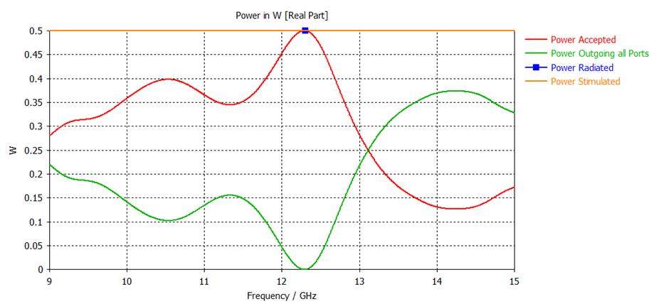
Figure-18: PowerExcitation.
PowerExcitation:Powerexcitationreferstotheprocessof feedingorsupplyingelectricalpowertoanantennaelement. Whenanantennaisexcitedorfedwithpower,itgenerates electromagneticwavesthatradiateintospacetotransmitor receivesignals.
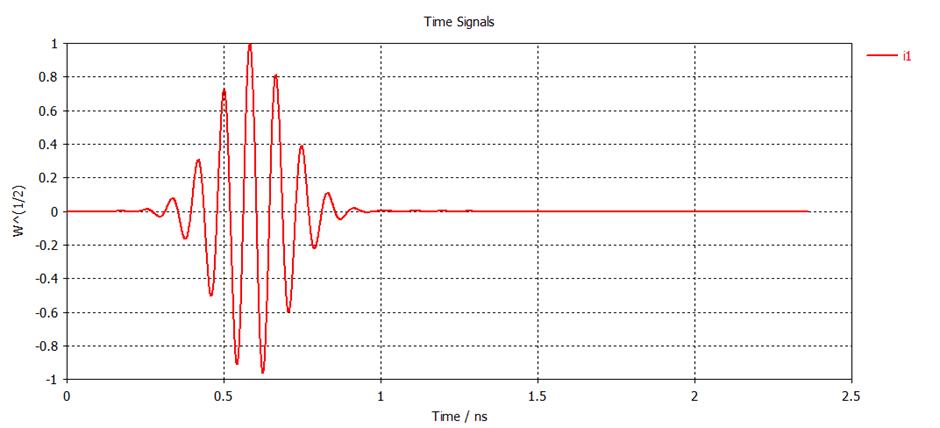
Figure-19: PortSignal.
PortSignal:Aportsignalinanantennareferstotheelectrical orelectromagneticsignalthatiseithertransmittedintothe antennaforbroadcastingorreceivedfromtheantennafor furtherprocessing.
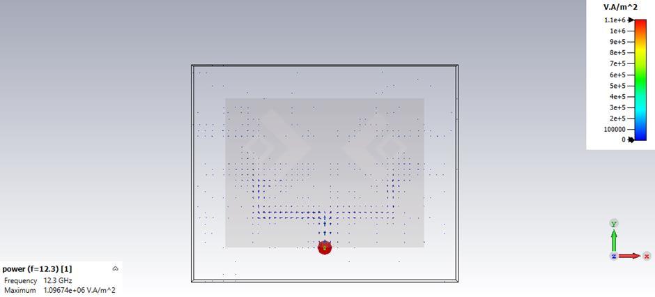
Figure-20: PowerFlow.
Power flow: The power flow of an antenna refers to the transfer and distribution of electromagnetic energy. In transmittingantennas,itdescribeshowelectricalpoweris convertedintoelectromagneticradiationthatpropagatesinto space. Receiving antennas characterize the process of capturingelectromagneticwavesfromtheenvironmentand converting them into electrical signals. Understanding the power flow is essential for assessing the performance and efficiencyofanantenna.
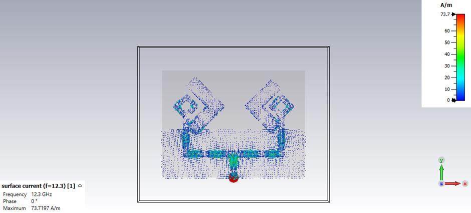
Figure-21: SurfaceCurrentat12.3GHz.
Surfacecurrent:Surfacecurrentinanantennareferstothe flowofelectriccurrentalongtheconductivesurfaceofthe antennastructure.
6. Application Of Wearable Antenna.

Figure-22: VariousApplicationsOfWearableAntenna.
7. CONCLUSIONS
The research paper's key contribution is its innovative approachtoshieldingtheantennafromtheadverseeffects of environmental dangers. In this study, a novel array antennahasbeenstudiedwhichworkson12.3GHzresonant frequency.A2-diamondshape2-Lcutantennaisdesignedin CSTsoftwarein whichitscharacteristicsareimproved by usingjeanssubstratewhichhasadielectricconstantof1.7 anditiscoveredwithpolyethylenesubstratewhichhelpsin protecting the antenna from wear and tear losses. If an individual wearing this antenna gets wet, it causes the antenna'scharacteristicstoalter,consequentlyimpactingits radiationpatterntoaddressthisissue,aflexibleantennahas beendesignedonatextilematerialwiththesamedielectric
International Research Journal of Engineering and Technology (IRJET) e-ISSN: 2395-0056
Volume: 11 Issue: 04 | Apr 2024 www.irjet.net p-ISSN: 2395-0072
constant.Theonlymodificationisthattheantennaisnow shieldedwithapolyethylenesubstrate.Theantennaisused for single band antenna with an improved bandwidth of 44.80%forfrequencyrange(12-12.55)GHzandtheoverall directivity is also increased which is better for communicationapplications.Thisantennaoffersprotection againstenvironmentalfactorssuchasrain,whichcanmake it wet and heavy. When it becomes wet, the change in its dielectric constant alters its properties, subsequently affecting the antenna's overall performance. Importantly, this antenna is well-suited for Internet of Things (IoT) applications.
Recentlythefrequenciesusedfor5Gmobilecommunication isabout1to6GHz.Inourresearchwehaveusedfrequency thatisbeyond10GHz,12.3GHzanditsbandwidthisaround 44.80%.Inthefuture,thistypeoffrequencycanbeusedfor andcanbeworkedfor6Gand7Gapplications.
[1] M.Chen,S.Gonzalez,A.Vasilakos,H.CaoandC.M.Leung, “Bodyareanetworks:Asurvey.”MobileNetworksand Applications,Vol.16,pp.171-193,2011.
[2] S.Movassaghi,M.Abolhasan,J.Lipman,D.Smith,andA. Jamalipour, “Wireless body area networks: A survey.” IEEECommunicationsSurveys&Tutorials,Vol.16,no.3, pp.1658-1686,2014.
[3] AnuragSaxena,VinodKumarSingh,“DesignofCompact Array Antenna and its Effect on Human Brain”, International Journal of Wireless Personal Communications,Springer(ISSN:0929-6212),February 2022.
[4] Yadav,A.;Singh,V.K.;Yadav,P.;Beliya,A.K.;Bhoi,A.K.; Barsocchi,P.DesignofCircularlyPolarizedTriple-Band WearableTextileAntennawithSafeLowSARforHuman Health.Electronic2020,9,1366,Published23August 2020.https://doi.org/10.3390/electronics9091366.
[5] Ashok Yadav, Vinod Kumar Singh, “Design of Ushape with DGS circularly polarized wearable antenna on fabric substrate for WLAN and C-Band applications” JournalofComputationalElectronics,September2019, Volume18,Issue3,pp.1103–1109,(ISSN:1569-8025) https://doi.org/10.1007/s10825- 019- 01342-2, Springer.
[6] VinodKumarSingh,SeemaDhupkariya,NareshBangari, “Wearable Ultra Wide Dual Band Flexible Textile AntennaforWiMax/WLANApplication”,International JournalofWirelessPersonalCommunications,Springer (ISSN:0929-6212),Vol95,Issue2,pp.1075–1086,2017.
[7] Yadav A, Kumar Singh V, Kumar Bhoi A, Marques G, Garcia-ZapirainB,delaTorreDíezI.WirelessBodyArea Networks: UWB Wearable Textile Antenna for Telemedicine and Mobile Health Systems, Micromachines,Vol. 11(6): E558,Published 30thMay 2020.
[8] A. K. Singh, R.A. Kabeer, M. Shukla, V. K. Singh, Z. Ali “Performance Analysis of First Iteration Koch Curve FractalLogPeriodicAntennaofVaryingAngles“Open Engineering (ISSN: 2391-5439), De Gruyter Publications,Volume3,Issue1,pp-51-57,March2013.
[9] A.Al-Sehemi,A.Al-Ghamdi,N.Dishovsky,N.Atanasov, andAtanasovaG,“Miniaturizedwearableantennaswith improvedradiationefficiencyusingmagneto-dielectric composites”.IETEJ.Res,Vol.65,no.3,pp.1-11,2019.
[10] D.ChaturvediandS.Raghavan,“Circularquartermode SIWantennaforWBANapplication,”IETEJ.Res.,Vol.64, no.4,pp.482–8,2017.
[11] Vinod K. Singh, Zakir Ali, Ashutosh Kumar Singh, ShahanazAyub“DualBandTriangularSlottedStacked Microstrip Antenna for Wireless Applications” Open Engineering (ISSN: 2391-5439), De Gruyter Publications,Volume3,Issue2,pp-221-225,June2013.
[12] AdityaTiwari,KanchanCecil,“ANovelThree-CutCircle Tri-Band Flexible Antenna for Wireless Application”, International Research Journal of Engineering and Technology(IRJET),Volume:10Issue:04Apr2023.
[13] I.Locher,M.Klemm,T.Kirstein,andG.Trster,‘‘Design andcharacterizationofpurelytextilepatchantennas,’’ IEEE Trans. Adv. Packag., vol. 29, no. 4, pp. 777–788, Nov.2006.
[14] KasifNisarParcha,SharulKamalAbdulRahim,PingJack Soh,MohsenKhalily,“WearableAntennas:AReviewof Materials, Structures, and Innovative Features for AutonomousCommunicationandSensing”,IEEEAccess 2019.K.Elissa,“Titleofpaperifknown,”unpublished.
BIOGRAPHIES

AyushiVinodia Student of Jabalpur Engineering College pursuing Masters Of Engineering.