
International Research Journal of Engineering and Technology (IRJET) e-ISSN: 2395-0056
Volume: 11 Issue: 04 | Apr 2024 www.irjet.net p-ISSN: 2395-0072
International Research Journal of Engineering and Technology (IRJET) e-ISSN: 2395-0056
Volume: 11 Issue: 04 | Apr 2024 www.irjet.net p-ISSN: 2395-0072
Rinil1 , Mijuwad P P2 , Adwaith A3 , Anaj T4 , Jibi R5, Jijo TM6
1234Graduate Student, 5Assistant Professor Department of Mechanical Engineering, AWH Engineering College Calicut, Kerala, India,6Production Manager KENZA TMT Steel Bar, Palakkad, Kerala, India. ***
Abstract – The steel industry is of paramount importance in the infrastructure development of a nation. Within this industry, the continuous casting method is employed to create semi-finished products such as slabs, blooms, and billets. The quality of steel billets is crucial for the production of superior steel goods. Flawless billets result in the manufacture of highquality steel products, while imperfect ones lead to a decrease in mechanical properties and the overall quality of the rolled product. In a recent project, common defects found in steel plants were identified in steel billets, and the causes of these defects were analyzed through a cause-and-effect diagram.
Key Words: Continuous casting, Billet, Cause and effect diagram, Blooms
The iron and steel sector has a lot of significance in India, contributing greatly to the country's industrial landscape. Steel,avitalandversatilematerial,playsapivotalroleinthe development of infrastructure.Indiastandsasthe world's second-largeststeelproducer,withthisindustryaccounting forroughly2.5%ofthenationalGDP,providingemployment opportunitiesforapproximately2.5millionindividualsboth directlyandindirectly.Atitscore,steelisanalloyofironand carbon,withcarbonlevelsrangingupto1.5%.Theprocessof continuouscastingservesasacrucialintermediarybetween steelproductionandrolling.Thismethodefficientlycreates semi-finished products by transforming molten steel into largeblocksknownasbillets.Automationlargelydrivesthis process, ensuring a continuous supply of metal through a mold,resultingintheproductionofbilletsorbloomsthatare furtherutilizedintherollingphase.Defectsinasteelbillet during continuous casting can significantly impact the qualityofthefinalrolledproduct.Thisstudydelvesintothe analysis of defects in continuous cast billets, leveraging statisticalqualitycontroltoolslikecause-and-effectdiagrams toidentifyandaddressingrootcauses.TheCause-and-Effect Diagram,alsoknownastheIshikawaorfishbonediagram, visually represents the relationship between a specific outcomeandthevariousfactorsinfluencingit.
1.Defectsofthesteelbilletincontinuouscasting.
Author:Anh-HoaBUIandVan-HungNGUYEN
Theprimarygoalofthisresearchistoidentifydeficienciesin the continual casting of steel billets, a critical aspect that impactsthequalityofrolledproducts.Thestudywascarried out to explore the flaws in 130×130 mm2 billets and to analyzetheircausesandpreventivemeasures.Theformation ofdefectsandcrackswaspredominantlyinfluencedbythe temperaturedistributionandcoolingprocessofthecasting strand. Notably, caster, rhomboidal billets, and off-corner cracks constituted the major portion of defects observed duringproduction.Thechemicalcompositionofthemolten metal and the secondary cooling procedure played crucial rolesinthedevelopmentofthesedefects.
2.ReformthePerformanceofaBilletQualitybyReducingits DefectsatSAIL-SCLKeralaLimited
Author:AbdulHaseebNC,AlexPJacob,ArvindKumar,Dibin Vincent
Exploredthedifferentprocedureswithintheindustryand successfully executed a project to enhance the quality of billets,resultingina reductionofsignificantlossesforthe company. The primary challenge encountered by the industry pertains to defects arising during the casting of billets. Defective billets can only be repurposed as scrap, leadingtosubstantiallosses.Analyzedtheunderlyingcauses of these defects and proposed solutions tailored to each scenario. Put forth the idea of utilizing a field mixing technology for blending molten metal in accurate proportions, thereby reducing defects by approximately 75%.Additionally,recommendedalternativeapproachesto enhancetheoverallqualityofbillets.
3.AnalysisoftheDefectofCrackinCasting
Author:VijayPandey
Thisresearchdelvesintothevariouskindsofinternaland externalfracturesthatcanpersistentlyemergeduringsteel casting.Eachcategoryofafractureisanalyzedconcerning theoperationalandmetallurgicalfactorsthatcanimpactthe developmentoffracturesduetotherobusthigh-temperature
International Research Journal of Engineering and Technology (IRJET) e-ISSN: 2395-0056
Volume: 11 Issue: 04 | Apr 2024 www.irjet.net p-ISSN: 2395-0072
mechanicalattributesofsteelandanunderstandingofthe stressesthatarisewithinthesolidifyingshell.Fracturestend tobeassociatedwithtwospecificzonesoflowsteelductility, notably a high-temperature area beyond 1340 °C, predominantlyaccountableformostfractures,encompassing allinternalfractures,andalow-temperatureregionranging from 700 to 900 °C, which leads to issues of transverse surfacecracking.Bycombiningthiscomprehensionwiththe stresses produced during continuous casting, feasible mechanisms of fracture formation can be proposed and linkedtooperationalandmetallurgicalfactors.
4.TheControlofPinholeandCrackDefectontheSurfaceof ColdHeadingSteelBillet
Author: WeiZhang, Liqiang Zhang,Ali Naqash2,Aonan Zhao,ChaojieZhang.
Theresearchprojectwasfocusedonexperimentsconducted on 10B21 boron-added cold heading steel, which showed some cracking issues during production. The examination throughvariousmethods,includingmacroscopicevaluation, microstructureexamination,scanningelectronmicroscope, energyspectrumanalysis,revealedthatdefectslikepinholes andcracksonthebilletsurfacewereprimarilycausedbythe presence of N and O elements, electromagnetic stirring, protectiveslag,andtemperaturevariations.Anoptimization procedure was suggested to mitigate these defects successfully.Byimplementingthisoptimizationprocess,the flawslikepinholesandsurfacecracksinthecastbilletwere effectivelyresolved.Consequently,thewirerodexhibiteda uniformstructurewithagrainsizeexceedinggrade8,and theforgedrod'scomplianceratereached100%.
Author:Dr.T.R.Vijayaram
The discussion presented here covers the process description,mechanism,andcontrolofcontinuouscasting.It delves into the hydrodynamics, heat transport, thermal analysis, solidification control, and heat transfer involved. Additionally,itexploresthevariousproducttypes,sections range, and the benefits of employing continuous casting technology in both ferrous and nonferrous foundries. Continuouscastingisamethodthatconvertsmoltenmetal intoasolidformcontinuously,encompassingseveralcrucial industrialprocedures.Thistechnology,whichinvolvesthe constantcastingofmetal,isknownforitsefficiencyandcosteffectiveness,makingitapopularchoiceformanufacturing varioussemi-finishedmetalshapes.Oncethemetaliscast,it canbefurtherprocessedaccordingly.Moreover,alltaskscan beeasilyautomatedandmonitored,facilitatingadjustments tothequalityandcharacteristicsofsemi-finishedproducts byalteringparameterssuchasthepullingspeed.
Author:Sachinahammed.CDr.N.M.Nagarajan
"Inthisstudy,aneffortisundertakentoexaminesteelbillets for the production of high-quality steel, specifically constructionalsteelwidelyusedinbuildingconstructionand various industries. The primary focus is on identifying defects in continuous cast products, investigating surface imperfectionsandcontrolmeasures,analyzingthechemical composition,anddeterminingthemechanicalpropertiesof thebillets.Thequalityofthebilletplaysacrucialroleinthe manufacturingofstructuralsteel,influencedbyfactorslike surfaceandinternalcracks,elementalcomposition,andbillet strength. Chemical composition analysis of the billets is performedusinganopticalemissionspectrometertoidentify thepercentageofelementspresent.Non-DestructiveTesting methods reveal surface cracks and internal imperfections. Mechanicalpropertiessuchasultimatestrength,yieldpoint, andelongationpercentagearedeterminedusingaUniversal TestingMachine(UTM)."
Author:MuhammedRaazick,Noorshan,RashidK,RumaisaC MSanmishalPK,Jibi.R
In this project, welded samples are subjected to nondestructivetestingtodetectany defectspresentinthe welds. Ultrasonic testing, dye penetrant testing, and magnetic particle inspection techniques are utilized for defectidentification.Anydefectsfoundarethenexamined usingacause-and-effectdiagram,oneofsevenqualitytools. Thisdiagramservesasarootcauseanalysistool,facilitating the structured investigation and resolution of underlying issuesthatcontributetotheproblemsdiscovered.
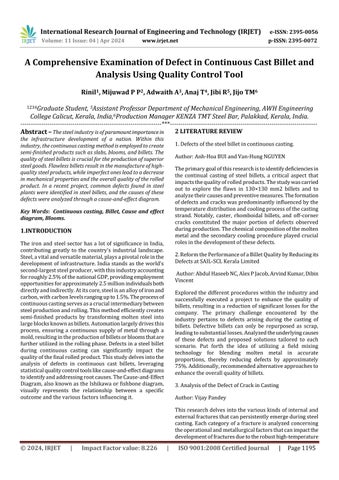
Themethodologystandscrucialformaintainingprojectflow and achieving desired outcomes. Essentially, it serves as a structuredframeworkintegratingprojectelementsaligning with objectives and the project's scope. A well-designed framework offers a comprehensive project overview and streamlines data retrieval processes. This encompasses conducting literature reviews, examining the company's background, applying various methods to identify defects, and conducting defect analyses using cause and effect diagrams.
International Research Journal of Engineering and Technology (IRJET) e-ISSN: 2395-0056
Volume: 11 Issue: 04 | Apr 2024 www.irjet.net p-ISSN: 2395-0072
Kenza TMT, established in 1991, is a private steel manufacturingcompanysituatedinthePalakkaddistrictof Kerala.RenownedforitsproductionofTMTsteelbars,Kenza TMT has earned recognition for its commitment to excellence, as evidenced by its Bureau of Indian Standard (BIS)certification.Focusedontheconstructionsteelsector, KenzaTMTutilizescontinuouscastingtechnologytoproduce 100X100mmsquarebilletsthroughanelectricarcfurnace. Theseironbilletsserveasthefoundationforvarioussteel productsusedinconstructionmaterialsandotherindustrial applications. The company offers TMT bars in a range of sizesincluding8mm,10mm,12mm,16mm,20mm,25mm, and 32mm. Fe550D garde steel bar are producing with following basiccomposition.
Constituent
Carbon 0.25
Sulpher 0.04
Phosphorous 0.04
Sulpherand Phosphorous 0.075
Billet manufacturing process
The journey of steelmaking from scrap begins with the collectionandsortingofsteelscrap. Steelscrapcomesfrom various sources, including end-of-life products, manufacturingtrimmings,anddefectiveitems.Thecollected scrap is sorted based on its properties and composition, whichiscrucialforensuringthequalityofthefinalproduct. Oncesorted,thescrapischargedintoaninductionfurnace. An 8-ton induction furnace is typically used for medium-
scaleproduction.Thescrapisloadedintothefurnaceusinga chargingbucket,andcareistakentoensurethatthescrapis clean and free from non-metallic materials. The melting process begins once the scrap is fully charged. Induction furnacesuseelectromagneticinductiontoproduceheatby passing alternating electric currents through coils surroundingthefurnace.Themeltingtemperatureforsteelis around1,370°Cto1,540°C.However,theexacttemperature canvarybasedonthegradeofsteelbeingproducedbythe company as it manufactures 2 grades of steel Fe500 and Fe550D. Thevoltageappliedduringthis processiscritical and is adjusted according to the furnace's design and the typeofscrapused.Typically,voltagescanrangefrom200V to 700V. After melting, the steel undergoes refining to remove impurities and adjust its composition. This is achieved through various processes, including oxidation, whereoxygenisblownthroughthemoltensteeltoremove carbon. The refining process also involves adding alloying elementslikemanganese,silicon,andcarbontoachievethe desiredsteelgrade.Duringtherefiningprocess,samplesof moltensteelaretakenperiodicallyforanalysis.Thisisdone tomonitorthechemicalcompositionandqualityofthesteel. The samples are analyzed using spectrometers and other laboratory equipment to ensure that the steel meets the required specifications. Once the steel has reached the desiredcompositionandtemperature,itistappedfromthe furnace. Tapping involves pouring the molten steel into a ladle for transport to the next stage of the process. The tappingtemperatureisusuallyhigherthanthemeltingpoint to ensure fluidity, typically around 1,600°C to 1,650°C. Secondaryrefining,orladlemetallurgy,followstapping. This process further adjusts the steel's composition, removes inclusions, and controls the temperature before casting. Techniques used in secondary refining include vacuum degassing, argon stirring, and ladle furnace heating. The refined steel is then cast into various shapes. Continuous casting is the most common method, where the steel is solidifiedintoslabs,blooms,orbillets.Thesesemi-finished products are then ready for further processing, such as rolling.IntheCCM,thesteel ispouredintoawater-cooled moldwhereitbeginstosolidify.Asthesteelexitsthemold,it enters a series of rollers that gradually reduce the steel's thicknesswhileitcontinuestosolidify.Thefinalshapeofthe steelisdeterminedbythedimensionsoftheCCM.
International Research Journal of Engineering and Technology (IRJET) e-ISSN: 2395-0056
Volume: 11 Issue: 04 | Apr 2024 www.irjet.net p-ISSN: 2395-0072
Plant layout
Thisfigureexploresthelayoutofthebilletmanufacturing sectionatKenzaTMT.Thissectionplaysacrucialrolein theoverallproductionprocess,transformingscrapsteel intobillets,theprimaryfeedstockforsubsequentstages. Byanalyzingthelayout,gaininsightsintotheproduction flow.
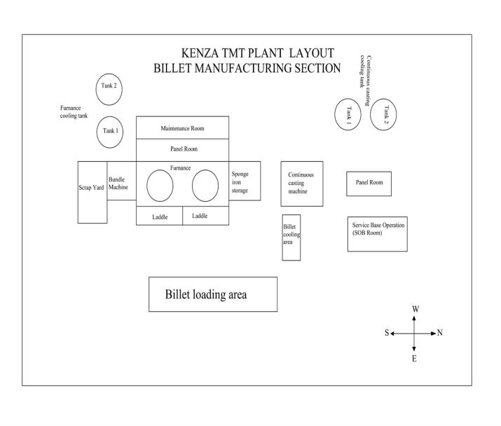
Raw Material Handling and Preparation
Scrap Yard: This specified location functions as a storage area for scrap metal before it undergoes processing into billets.
Bundle Machine:Positionedincloseproximitytothescrap yard, this device compresses scattered scrap metal into organized bundles to streamline the process of loading furnacesefficiently.
Electric Furnace Operations and Maintenance
Electric Furnace Functionality:Thediagramillustratesthe presence of two electric arc furnaces. However, only one furnace is utilized at a time to melt steel scrap efficiently, minimizingenergyconsumption,whileensuringcontinuous productioncapacity.
Command Centre:Positionedbehindtheelectricfurnace, this section accommodates the systems responsible for controlling the furnace's operations. The command centre facilitates meticulous regulation of temperatures and constantmonitoringofthemeltingprocess.
Equipment Maintenance Facility:Situatedadjacenttothe commandcentre,aspecializedmaintenanceareaguarantees the seamless functioning of the electric furnace. Skilled technicians can conduct preventive maintenance and promptlyaddressarisingissues.
Steel Refinement and Casting Operations
Primary and Secondary Water Reservoirs (Left of Maintenance Facility): Strategically located, these reservoirssupplycoolingwaterfordualpurposes.Onesetof
International Research Journal of Engineering and Technology (IRJET) e-ISSN: 2395-0056
Volume: 11 Issue: 04 | Apr 2024 www.irjet.net p-ISSN: 2395-0072
reservoirs helps in cooling the coils inside the electric furnace,maintainingidealoperationaltemperatures.
Sponge Iron Stockpile:On-sitestoragehousesspongeiron, aporousironvariantwithminimalcarboncontent.Specific quantitiesofspongeironcanbeincorporatedintothemolten steel bath during the melting process as necessary, regulatingthefinalsteelbillets'carboncontent.
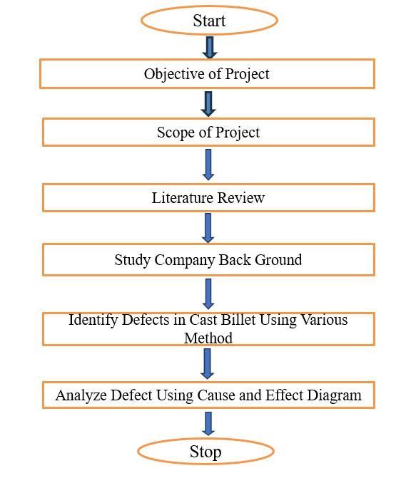
Continuous Casting Machinery (CCM): The molten steel from the electric furnace is transferred to the CCM for casting. This machine continuously shapes the liquid steel into elongated solid forms known as billets. The casting processparametersarevigilantlysupervisedandadjusted fromtheadjacentCCMcontrolpanelandoperationalbase.
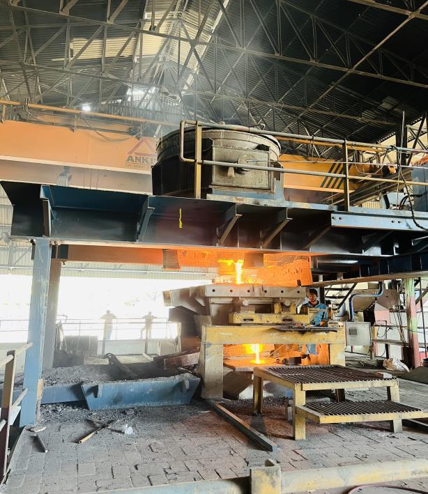
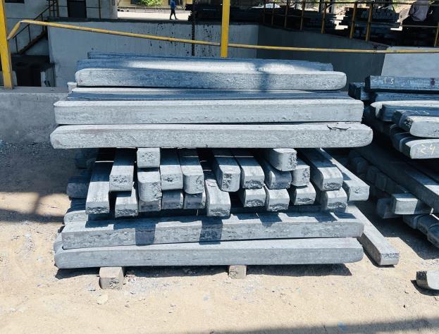
Cooling Section for Billets: Following the continuous casting process, newly formed billets are transported to a specificareadesignatedforcooling.Itisinthisspacethatthe billetsareallowedtonaturallylowertheirtemperaturetoa controlled level before moving on to the next stage of handling.
Water Reservoirs for Cooling (Located Behind the CCM Control Panel):Theseprimaryandsecondarywatertanks, similar to those near the furnace, are responsible for providingthenecessarywaterforthecoolingofsteelbillets duringthecontinuouscastingoperation.
Billet Loading Zone:Servingasthefinaldestinationwithin the billet production area, this zone is where the cooled billets are typically loaded for transportation to the subsequentprocessingphase,ofteninvolvingtherollingmill fortheirtransformationintosteelbars.
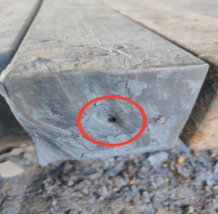
Non-destructive testing (NDT) encompasses a range of analytical techniques utilized to assess the properties of a materialwithoutcausingpermanentchangestothematerial under inspection. This method, which includes visual inspection,liquidpenetranttesting,magneticparticletesting, ultrasonic testing, and radiographic testing, proves to be invaluable in terms of saving time and money. Nondestructive testing is synonymous with non-destructive evaluation, nondestructive analysis, non-destructive examination,andnon-destructiveinspection.FollowingNonDestructivetestingconductedoverthebillet.
1.Visiual inspection 2. Liquid penetrant test. 3.Magnetic particletest.4.Ultrasonictest. 5.Radiographictesting.
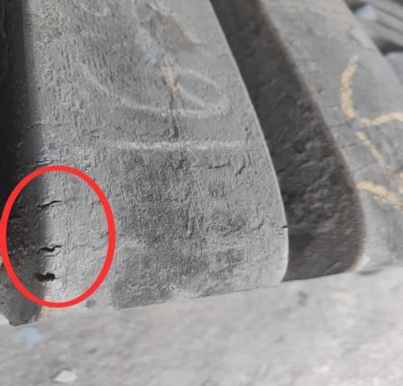
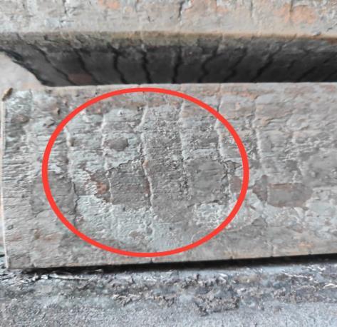
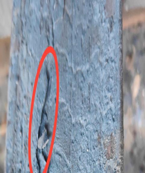
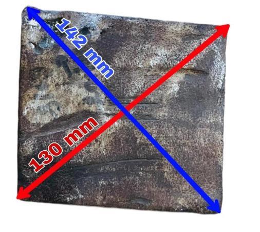
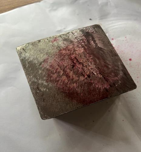
Visual inspection: Visualinspection,forinstance,involvesa straightforwardandcost-efficientapproachtoexaminingthe surfaceandinternalcharacteristicsofacasting,allowingfor the identification of any apparent defects through a
meticulousassessmentwiththenakedeyeoramagnifying glass. These defects may be pinpointed in a 100x100mm squarecastingbilletthroughvisualinspection.
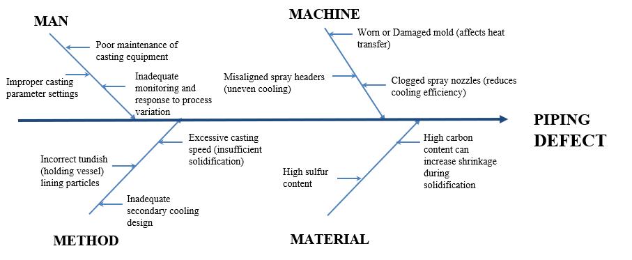
Piping
International Research Journal of Engineering and Technology (IRJET) e-ISSN: 2395-0056
Volume: 11 Issue: 04 | Apr 2024 www.irjet.net p-ISSN: 2395-0072
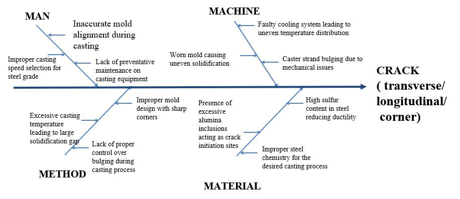
LongitudinalCrack
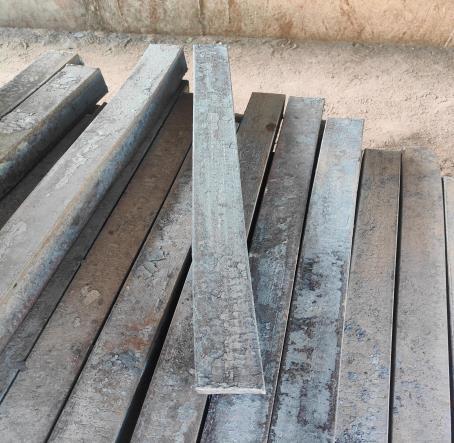
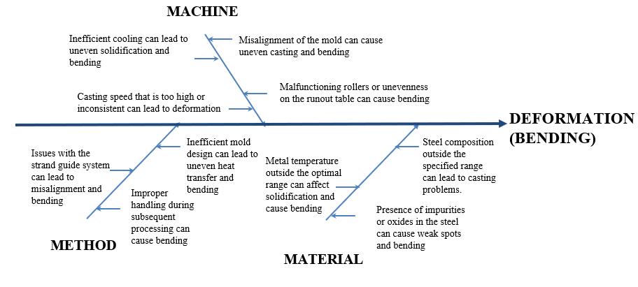
Deformation(Bending)
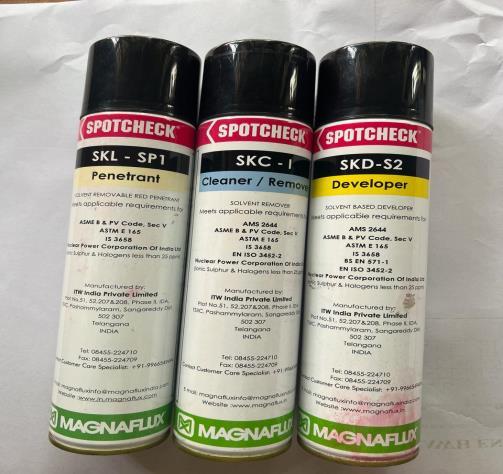
Liquid penetrant test: Theliquidpenetranttestisa nondestructive examination method used to detect surface discontinuities in various materials, including ferrous and non-ferrousmetals,aswellasnon-metallicsubstanceslike ceramics, plastics, and glass. These processes can identify flawssuchascracks,seams,laps,coldshuts,andlaminations. Theuse ofliquid penetrant forflawdetectionis becoming moreprevalentacrossindustries,emphasizingtheneedfor generalrecommendationstoguideitsapplicationeffectively.
International Research Journal of Engineering and Technology (IRJET) e-ISSN: 2395-0056
Volume: 11 Issue: 04 | Apr 2024 www.irjet.net p-ISSN: 2395-0072
Procedures
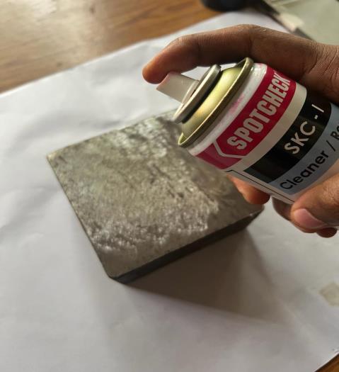
a) Pre-cleanpart
This involves cleaning the part, ranging from grinding or wire brushing to wiping it with a cloth dampened with a cleanerorremover.Thesurfacemustberidofanydirt,rust, scale,paint,oil,andgrease,ensuringasmoothsurfacefreeof anypenetrantresidue
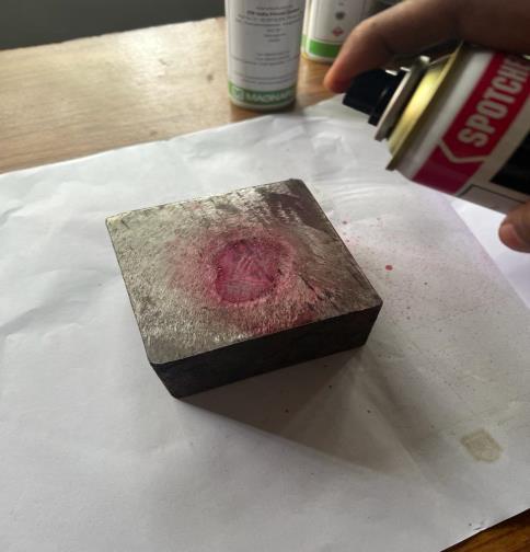
b)Applypenetrant.
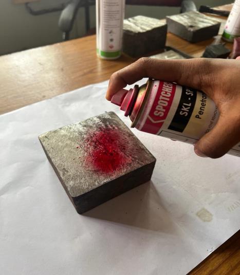
14:PenetrantApplying
c)Removepenetrant.
Thoroughlycleanthepartbyusingclean,dry,lint-freerags toremoveallpenetrantuntilnotracesremainvisible.Utilize cleaner/remover sprayed on a fresh rag to eliminate any remainingpenetrant,ensuringaspotlesssurface.
15:PenetrantRemoving
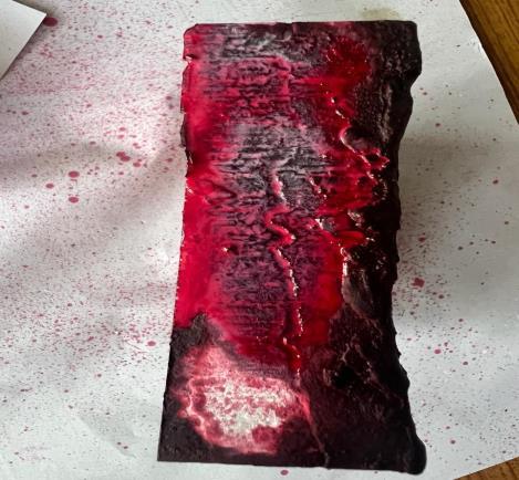
d)Developerapplication.
Apply a light, thin coating of developer on the part under examination. Allow time for the dye to escape flaws and create a visible indicationin thedeveloper. The developer should be left for a dwell time of 10 to 60 minutes for optimumresults.
International Research Journal of Engineering and Technology (IRJET) e-ISSN: 2395-0056
Volume: 11 Issue: 04 | Apr 2024 www.irjet.net p-ISSN: 2395-0072
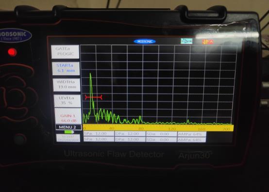
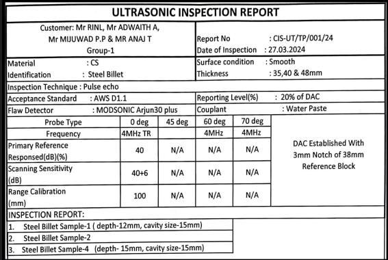
Ultrasonic Testing: Ultrasonictesting(UT)isawidelyused non-destructivetesting(NDT)techniquethatutilizeshighfrequency sound waves to evaluate the properties of a material. UT works by introducing sound waves into the materialandanalyzingthereflectedwavestodetectinternal flaws,measurethickness,andassessthematerial'soverall integrity.Priortotesting,thebilletsurfacewaspreparedby grindinganyirregularitiesexceeding0.5mmdepthtoensure optimalsoundwavetransmission.Acouplant,inthiscasea low viscosity oil, was applied to the prepared surface to minimizeairgapsthatcouldhindersignaltransmission.The UTinspectionutilizedapulse-echotechniquewitha45MHz longitudinal wave transducer. The transducer was systematicallyscannedacrosstheentirebilletsurfaceina raster pattern, ensuring complete coverage. The UT flaw detector was calibrated with a reference block of known dimensions and material properties to ensure accurate positioning and sizing of any potential defects. During testing, the A-scan presentation on the UT display was continuouslymonitoredforsuddensignalamplitudechanges oradditionalechoesindicativeofinternaldiscontinuities. All detected anomalies were documented, including their location, size, and character based on the reference standards. The figure below shows the ultrasonic flow detector.
International Research Journal of Engineering and Technology (IRJET) e-ISSN: 2395-0056
Volume: 11 Issue: 04 | Apr 2024 www.irjet.net p-ISSN: 2395-0072
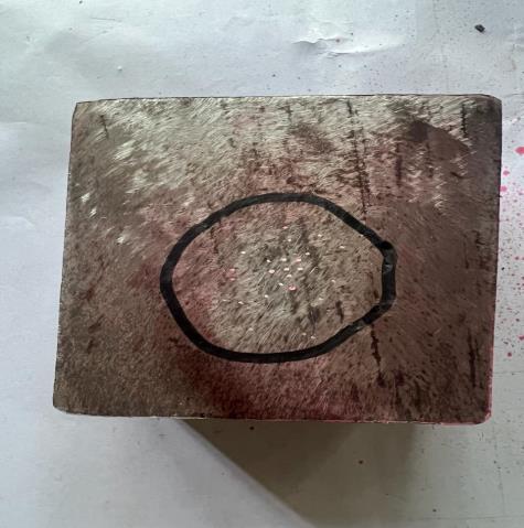
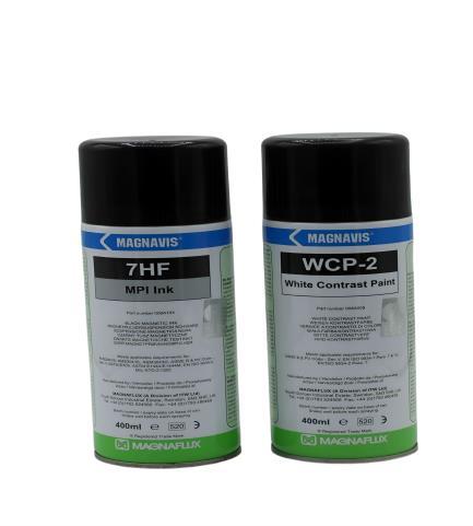
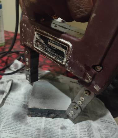
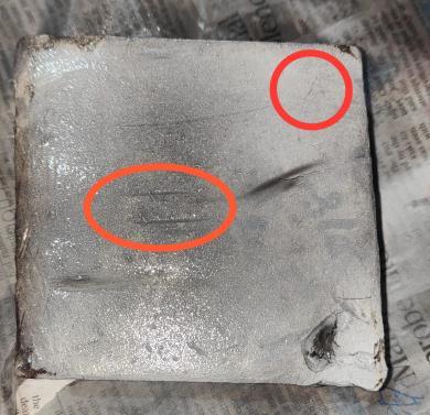
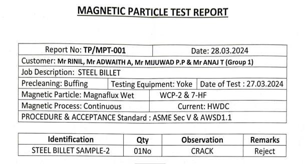
Magnetic Particle Inspection: Magnetic Particle Examination (MPE) serves as a Non-Destructive Testing (NDT)techniqueaimedatdetectingflawssuchascracksin ferromagnetic materials like steel. This method involves magnetizingthematerial,disturbingthefieldarounddefects. Subsequently,ironparticlesareattractedtotheseareasof magneticfluxleakage,allowingforthevisualidentificationof defects. While MPE is efficient and cost-effective, it is specifically applicable to ferromagnetic substances. To investigateanysurfaceorsubsurfacecracks,thesteelbillet underwent magnetic particle examination (MPE). Before conductingtheexamination,thebilletunderwentathorough cleaning process to eliminate any potential contaminants that could affect particle adhesion. Furthermore, a white background paint was applied to enhance the visibility of crack indications. Employing the yoke method for magnetizationinvolvedplacingahand-heldelectromagnet across specific regions of the billet to induce a strong magnetic field longitudinally. Wet magnetic particles, a suspension of finely divided ferromagnetic particles in a carrier liquid, were subsequently administered onto the painted surface of the billet. The continuous steel matrix directed the magnetic field lines, but imperfections like cracks led to a disruption in this flow, attracting the wet magneticparticlesandcreatingvisibleaccumulationsalong the crack path. Systematic scanning of the entire billet surface was carried out using the yoke in various orientationstoensurecompletecoverage.Afterexamination, residual magnetization was eliminated using a demagnetizing coil, and the wet magnetic particles were meticulously cleaned from the billet's surface. This MPE procedure facilitated a prompt and reliable assessment of surfacecrackdefectsonthesteelbillet.
Radiographic Testing: RadiographicTesting,alsoknownas RTinthefieldofNon-DestructiveTesting(NDT),utilizesXrays or gamma rays to penetrate materials and identify internalflaws.Differentdensitieswithinthematerialabsorb radiationdifferently,resultingindarkerareasonthefilmor digital detector. Skilled inspectors carefully analyze these imagestopinpointcracks,voids,orotherimperfections.RT offers versatility, deep inspection capabilities, and the advantage of producing permanent records. However, its operation necessitates stringent safety measures and specializedtrainingduetotheinvolvementofradiation.In anassessmentoftheinternalstructureofacontinuouslycast
International Research Journal of
Volume: 11 Issue: 04 | Apr 2024 www.irjet.net
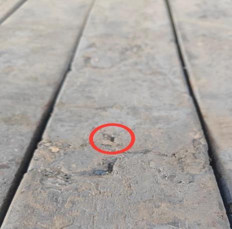
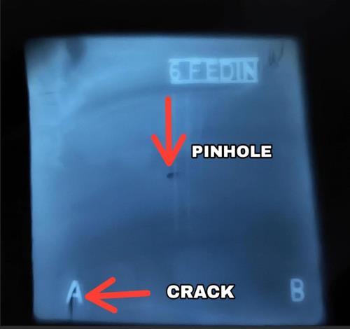
steelbillet,radiographictestingplayedacrucialrole.Priorto thetestingphase,thesurfaceofthebilletwasmeticulously cleanedtoeliminateanysubstancesthatcouldimpedethe passage of radiation. To ensure accurate alignment and minimize dispersed radiation, the billet was precisely positionedbetweentheX-raysourceandtheradiographic filmcassette.ThedistancebetweentheX-raysourceandthe billet, determined by its thickness and the desired image quality,wasmeticulouslyset.Exposureparameterssuchas kilovoltage (kV) and milliamperage-seconds (mA·s) were thoughtfully adjusted to achieve optimal penetration and image contrast. After the irradiation process, the radiographicfilmunderwentstrictprocessinginadarkened environmentusingestablishedchemicaltechniquestocreate apermanentrecordofthebillet'sinternalconfiguration.The resultingradiographwasscrutinizedindetailbyaqualified inspector using a calibrated light box to identify any discontinuities like cracks, porosity, or shrinkage cavities within the billet. This systematic approach employed in specimen preparation, radiographic exposure, and film processing guaranteed the attainment of top-quality radiographsforthemeticulousevaluationofthesteelbillet's integrity. Pin hole and crack defects were successfully detectedthroughthecomprehensiveradiographicinspection techniqueused.
Pinholeandcrackdefectareidentifiedusingradiographic inspectiontechnique.
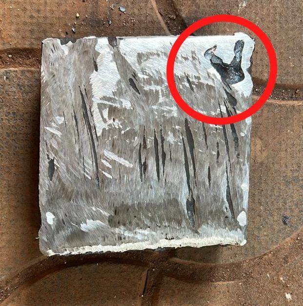
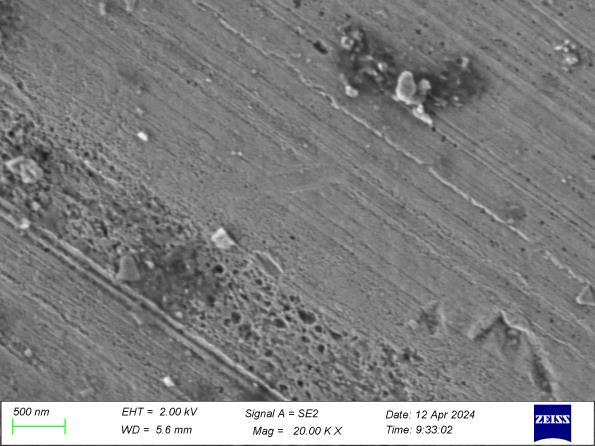
Microscopic Examination of a
A section of the steel billet was meticulously prepared for microstructural investigation through the utilization of a Scanning Electron Microscope (SEM). The sample was subjected to grinding, polishing, and etching to achieve a sleek,reflectivesurfacethataccentuatesthemicrostructure of the material. Subsequently, the SEM analysis employed secondaryelectronimagingtounveildetailsregardingthe dimensions,shapes,anddistributionofthevariousphases presentwithinthesteelbillet.Avisualdepictionofthetest pieceextractedfromtheSEMexaminationisincludedbelow.
Quality control tools encompass various methods and techniques utilized to guarantee that a product or service aligns with the desired quality standards. These tools are applicableatanyphaseoftheproductionprocess,ranging frominitialdevelopmenttoultimatedelivery.
Thesevenbasicqualitycontroltoolsare:
1.Cause-and-effectdiagram(Ishikawadiagram)
2.Checksheet
3.Controlchart
International Research Journal of Engineering and Technology (IRJET) e-ISSN: 2395-0056
Volume: 11 Issue: 04 | Apr 2024 www.irjet.net p-ISSN: 2395-0072
4.Histogram
5.Paretochart
6.Scatterdiagram
7.Stratification(orflowchart)
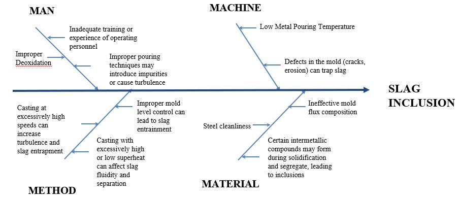
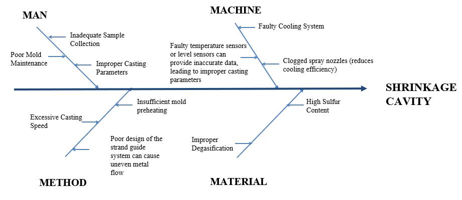
A cause-and-effect diagram, commonly referred to as an Ishikawa or “fishbone” diagram, serves as a visual instrument used to investigate and present the potential causesofaspecificoutcome.
Rootcauseanalysisofdefects
Cause and effect analysis showing major causes of the continuouscastingbilletdefects.
Piping
Slaginclusion
International Research Journal of Engineering and Technology (IRJET) e-ISSN: 2395-0056
Volume: 11 Issue: 04 | Apr 2024 www.irjet.net p-ISSN: 2395-0072
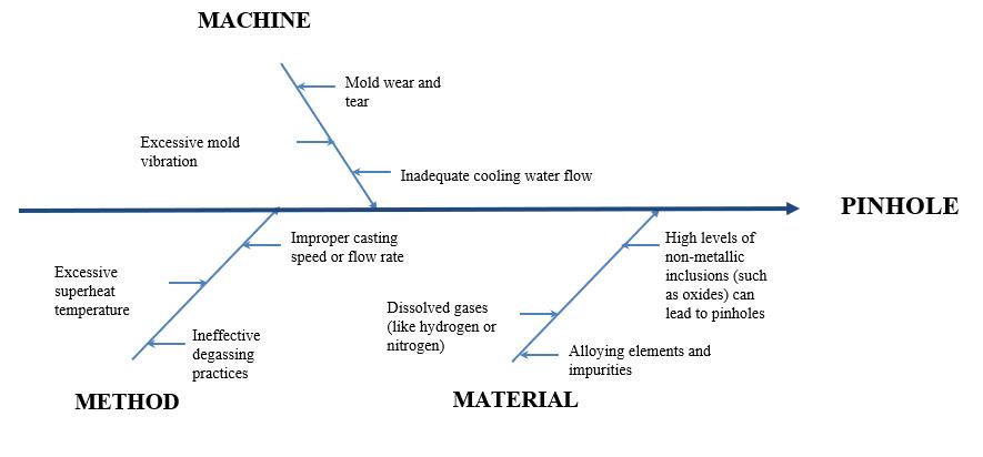
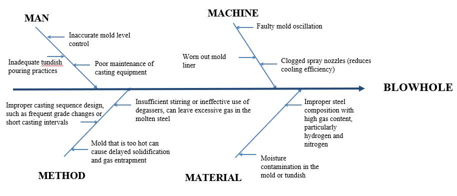
Fig33:CauseandeffectdiagramforBlowHole Rhomboidity
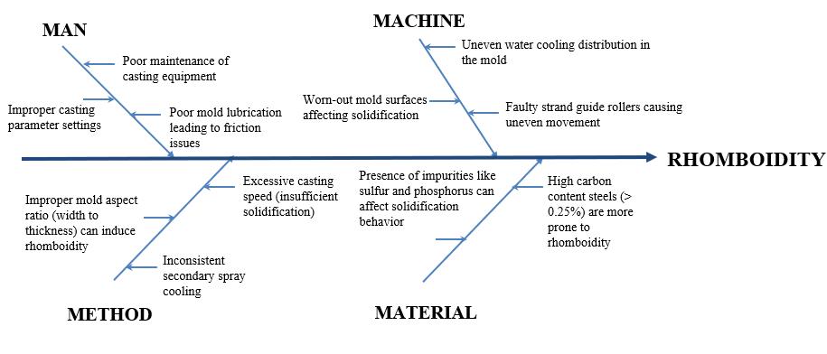
34:CauseandeffectdiagramforRhomboidity
Industrial case study of continuous casting defects is discussedin this paper byusingcauseand effectdiagram. Variousdefectsarefoundoutusingnondestructivetesting. By using cause and effect diagram various causes and remedialmeasuresarediscussed.Thisinvestigationwillbe highly useful in reducing casting defect in industries and inprovingthequalityofcastingwithlessrejections.
[1] “Defectsofthesteelbilletincontinuouscasting.” AnhHoa BUI and Van-Hung NGUYEN Journal of Metals, MaterialsandMinerals,Vol.30,No.1,pp.80-85,2020
[2]“ReformthePerformanceofaBilletQualitybyReducing itsDefectsatSAIL-SCLKeralaLimited”AbdulHaseeb NC,AlexPJacob,ArvindKumar,DibinVincentIJIRST–InternationalJournalforInnovativeResearchinScience &Technology|Volume1|Issue12|May2015.
[3]“AnalysisoftheDefectofCrackinCasting”VijayPandey JETIRApril2019,Volume6,Issue4.
[4]“TheControlofPinholeandCrackDefectontheSurface of Cold Heading Steel Billet” WeiZhang, Liqiang Zhang,Ali Naqash,Aonan Zhao, Chaojie Zhang. International Journal of Research Studies in Science, EngineeringandTechnologyVolume6,Issue7,2019,PP 15-21IJARIIEVol-4Issue-22018
[5]“MetallurgyofContinuousCastingTechnology”Dr.T.R. Vijayaram International Journal of Manufacturing & Industrial Engineering Volume1: Issue1 ISSN:23741589
[6]“Studies on Production of Quality Billets for Constructional Steels” Sachin ahammed.C Dr. N. M. Nagarajan International Journal of Innovative Science, Engineering & Technology, Vol. 2 Issue 9, September 2015.
[7]“DefectReductioninanArcWeldingProcessUsingCause and Effect Diagram” Muhammed Raazick, Noorshan, RashidK,RumaisaCMSanmishalPK,Jibi.International Journal of Engineering and Innovative Technology (IJEIT)Volume5,Issue11,May2016.
[8] ASM Metals HandBook Volume 17 - Nondestructive EvaluationandQualityControl.
[9] Bureau of Indian Standards IS 15431 (2003): Seven BasicToolsforQualityManagement.
[10]DalgobindMahto;AnjaniKumar“Applicationofroot cause analysis in improvement of product quality and productivity”JIEM,2008–01(02):16-53-ISSN:20130953
International Research Journal of Engineering and Technology (IRJET) e-ISSN: 2395-0056
Volume: 11 Issue: 04 | Apr 2024 www.irjet.net p-ISSN: 2395-0072


Mr. Rinil Final year B-tech student in the MechanicalEngineeringDepartmentatAWH EngineeringCollegeCalicutKeralaIndia
Mr. Mijuwad. P P FinalyearB-techstudentin the Mechanical Engineering Department at AWH Engineering College Calicut Kerala India.
Mr.Adwaith.A Final year B-tech student in the Mechanical Engineering Department at AWH Engineering College Calicut Kerala India.
Mr.Anaj.T Final year B-tech student in the MechanicalEngineeringDepartmentatAWH EngineeringCollegeCalicutKeralaIndia
Mr Jibi R CurrentlyworkingasanAssistant Professor in the mechanical engineering department at AWH Engineering College CalicutKeralaIndia.
Mr.Jijo.TM CurrentlyworkingasProduction managerinKENZATMTSteelBar,Palakkad, Kerala,India