
International Research Journal of Engineering and Technology (IRJET) e-ISSN: 2395-0056
Volume: 11 Issue: 04 | Apr 2024 www.irjet.net p-ISSN: 2395-0072
International Research Journal of Engineering and Technology (IRJET) e-ISSN: 2395-0056
Volume: 11 Issue: 04 | Apr 2024 www.irjet.net p-ISSN: 2395-0072
J. Jaya Keerthana1 , M. Anupama Latha2 , M. V. S. Kathik3 , M. Manikanta4, M. Raghavendra Rao5
1Assistant Professor, Department of ECE, Seshadri Rao Gudlavalleru Engineering College, Gudlavalleru 2,3,4,5Student, Department of ECE, , Seshadri Rao Gudlavalleru Engineering College, Gudlavalleru
Abstract - Ultra-wideband(UWB)antennashave recently gained prominence in communication, radar technology, and electronic warfare domains. The quick development of these antennas is due to the wide bandwidth requirements of pulse radar, ground penetrating radar, electromagnetic compatibility, spaceborne communication systems, stealth target detection, and more. Aiming to address the defects of existing UWB antennas, which often have narrow bandwidth and low gain, a planar ultra-wideband microstrip array antenna can be designed to achieve good ultra-wideband characteristics and effectively improve the gain of the antenna by loading multiple steps on monopole patch, defected ground structure and implementing array with different feedings. The initial bandwidth of the rectangular monopole antenna was 10GHz–20GHz. After loading multiple steps on the monopole patch, the bandwidth was increased to between 10 and 45GHz. Using thenewultra-widebandarraymethodthatcombinesseries feed and angle feed and the defective ground structure (DGS), the array maintains the ultrawide bandwidth span of 10–45GHz of the array element, and the maximum gain of the antenna in the bandwidth was increased from 4.72dBito9.34dBi.Thechallengeofimpedancematchingof antenna units in ultra-wideband is resolved by the novel array technique, which also increases the antenna’s gain withinthebandwidth.Theantennasimulationisconsistent with the measurement results. With its extensive operating frequency band, high gain, compactness, and favorable radiation attributes, this newly designed antenna holds significantpromiseforapplicationinUWBradarsystems.
Key Words: Ultra-wideband antennas, defective ground structure (DGS), Array Antenna,
1.INTRODUCTION:
Ultra-widebandantennasplayacrucialroleinUWBradar systemsandareindispensablemicrowavecomponentsin UWB wireless technology. The rapid progress in ultrawideband antenna technology is primarily motivated by the increasing need for wide bandwidth in applications like pulse radar, ground penetrating radar, electromagnetic compatibility, spaceborne communication systems, stealth target detection, and more. With the advancement of electronics and information technology, there is a noticeable shift
towards enhancing ultra-wideband antennas in terms of both size reduction and wider bandwidth. This field has emerged as a key area of focus for research in recent times. Planar antennas are extensively utilized in the realm of ultra-wideband due to their cost-effectiveness, compact design, low profile, and broad impedance bandwidth. However, during the antenna design phase, factors such as stability of antenna pattern, radiation efficiency, and antenna volume must also be taken into account, posing challenges in the development of ultrawidebandantennas.
Researchers have extensively studied ways to enhance the bandwidth of microstrip antennas, valued for their small size and flat profile. Techniques include altering patch shapes, adding slots or grounding structures, and using defective structures. In the studies [1-4], various designs like U-shaped slots, E-shaped patches, and stacked patches have been explored. For example, Majidzadeh et al. [5] introduced a quasi-square patch with steps and a rectangular slot, achieving a bandwidth from 2.78 GHz to 19.38GHz.Anotherstudy[6],featuredabroadbandprinted monopole antenna with a peak gain of 4.1 dBi across the entireUWBspectrum.Otherdesigns,like[7],arectangular microstrip patch with truncated corners, achieved bandwidths from 3.1 GHz to 10.6 GHz with gains up to 3.3 dBi. Nevertheless, monopole microstrip antennas often demonstrate limited gain across the entire bandwidth. In order to enhance the gain of the UWB antenna, it is essential to employ an array configuration of microstrip antenna elements. However, the overall bandwidth of the microstrip antenna array, formed by connecting each unit with the microstrip line, is affected due to the constrained bandwidth of the microstrip line itself. Consequently, it is valuable to investigate methods of utilizing a microstrip antenna array to augment gain without significantly compromisingantennabandwidth.
Current research on planar UWB arrays focuses on series feed[8], parallel feed[9-18], fractional and Fibonacci arrays[19,20], and MIMO arrays[21]. The series feed structurehaslimitedbandwidth,requiringadjustmentslike extending the feed point into the patch and optimizing feeder-patch distance. In [8], a three-series log-periodic antenna achieved a bandwidth of 12.2 GHz to 21.71 GHz with increased gain. Another study[12] utilized a UC-EBG structureandparallelfeedingforawearableantennaarray
International Research Journal of Engineering and Technology (IRJET) e-ISSN: 2395-0056
Volume: 11 Issue: 04 | Apr 2024 www.irjet.net p-ISSN: 2395-0072
with high gain. An 8x8 microstrip array achieved an impedancebandwidthof22GHzto46.3GHzandmaximum gain of 23.4 dBi. In [21], Fractal and Fibonacci techniques expandedthebandwidthofamicrostripunit.Atriplebandstop MIMO/diversity UWB antenna operated in three frequency bands, enhanced by zigzag patch design, decouplingstrips,andgroundslotstructureforisolation.
The paper outlines an innovative design for an ultrawidebandarrayantenna,combininghorizontalcornerfeed and vertical series feed for construction. Each array element has multiple current excitation points to cover various frequency bands simultaneously, ensuring performance across different frequency bands without interference. The feed network is compact, enhancing efficiency. Compared to previous designs, this antenna offers a broader bandwidth range and satisfactory gain levels. Additionally, the design features a stepped ultrawideband microstrip antenna unit and a novel microstrip array approach, achieving an impedance bandwidth from 10GHzto45GHzwithamaximumgainof9.25dBi.
The ultra-wideband antenna described in this study functionswithinthefrequencyrangeof10GHzto45GHz. Achieving an ultra-wideband design for the microstrip antenna unit involves incorporating multiple steps on the rectangular unit. The multilevel stepped structure at the edge of the microstrip patch proves to be an effective method for expanding bandwidth, reducing size, and achieving ultra-wideband capabilities. As the strong current of the patch is mainly concentrated at the edge, modifications made at the edge significantly impact the currentdistributionoftheantenna,therebybroadeningits operationalbandwidth.
Processing the edge of the patch has a notable impact on the antenna's current distribution, leading to increased bandwidth. To enhance the antenna's bandwidth, this study introduces the loading of 4 steps onto the patch's edge. Figure 1(b) displays the simulation structure of the radiation unit loaded with 4 steps. The width of the antenna steps is optimized, resulting in the following dimensions: width of the rectangular patch part = 7 mm, length =6.5mm,feedlinelength=5mm,feedlinewidth = 0.5 mm, ground plate width = 4.7 mm, all steps having the same dimensions with a side length of 0.5 mm. The antenna unit has overall dimensions of 6.5 mm × 14 mm. The simulation results in Figure 2 demonstrate the Sparameters when loading a 4-level stepped antenna. This antennahas4resonancepointsatfrequenciesof11.3GHz, 23 GHz, 30.8 GHz, and 40 GHz. The antenna's bandwidth range is from 10 GHz to 45 GHz. Each resonance point corresponds to a step size of the antenna. Figure 3 displaysthecurrent
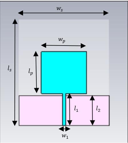
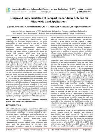
Fig -1(a): Rectangularradiationpatchantenna
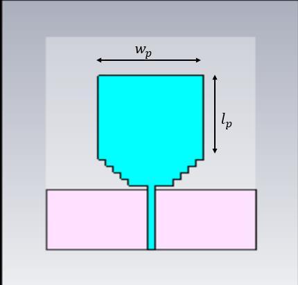
Fig -1(b): 4-levelladderradiationpatchantenna
distribution of the 4-level stepped antenna at each frequency point. It is evident that the current is evenly spreadalongthepatch'sedgeandthefeeder.However,as the frequency changes, the current distribution and workingmodelsignificantlyalter,resultinginvariationsin the antenna's pattern and impedance. This poses challenges for impedance matching in ultra-wideband antennaelements.
Fig -2: S-parametersofrectangularradiationunitand4levelladderelementantenna.
International Research Journal of Engineering and Technology (IRJET) e-ISSN: 2395-0056
Volume: 11 Issue: 04 | Apr 2024 www.irjet.net p-ISSN: 2395-0072
Theaveragegainofamonopoleantennaistypicallyonly35 dBi, which falls short of the requirements for a radio systemdespite providing basictransmissionandreception capabilities. To overcome this limitation and improve the antenna'sgainand directivity,itisoftennecessarytoform an array. However, designing ultra-wideband arrays poses challenges due to the significant changes in internal field distribution and working model with frequency, as well as fluctuationsinportimpedance.
The proposed composition method for UWB arrays involves a combination of series feed and corner feed, enabling multiple feed points on the array element to enhancebandwidth.Variationsinfeederlength,width,and impedance across multiple frequency bands ensure impedance matching and bandwidth. Implementing this design improves antenna gain, addressing low gain in existing wideband antennas. Figure 4, illustrates the antenna simulation model. The radiation unit uses a radiation patch loaded with four steps, adopting series feeding in the longitudinal direction and corner feeding in thetransversedirectionforoptimalperformance.

-3: Currentdistributionof4-levelsteppedantenna:
(a)11.3GHz,(b)23GHz,(c)30.8GHzand(d)40GHz
PARAMETERS DIMENSION (in mm)
Widthofthesubstrate 14
Heightofsubstrate 0.254
Lengthofsubstrate 16.5
Lengthof the patch 6.5
Widthof the patch 7
Lengthofground 4.7
Widthoftheground 14
Lengthofthefeedline 5
Widthofthefeedline 0.5
Heightofportfeed 0.254
Widthofportfeed 0.5
Lengthofthestepsize 0.5
Widthofthestepsize 0.5
Table -1: Dimensionsofsimplepatchantenna
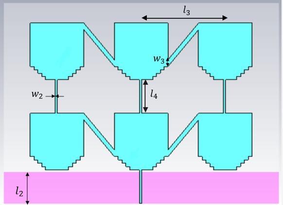
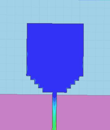
ModelandsimulatetheantennaasshowninFigure4.The simulation analysis of the patch transverse spacing l3 is carried out. To study the impact of corner-fed microstrip line on the antenna resonant frequency and pattern, changethetransversespacingl3from9to13mminsteps of1mm.
International Research Journal of Engineering and Technology (IRJET) e-ISSN: 2395-0056
Volume: 11 Issue: 04 | Apr 2024 www.irjet.net p-ISSN: 2395-0072
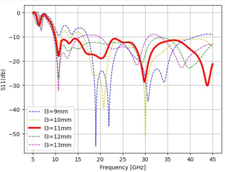
Figure 5:VariationofresonantfrequencyandSparameterswiththetransversespacingl3
Figure 5 shows the change of resonant frequency and Sparameters of the antenna with the transverse spacing of the patch l3. With the increase of the spacing l3, each resonant point gradually shifts to the low frequency direction. Among which, the first and second resonant points tend to fuse. The S-parameter value of the third resonantpointgraduallydecreases.Thereturnloss ofthe fourthresonantpointisbetween−20dBand−30dB.After extensive analysis, it was determined that the transverse spacingl3shouldbe11mmbecause,whenl3issmall,the antenna does not resonate in the frequency range of 10 GHz–20GHzandtheimpedanceisnotmatched,andwhen l3islarge,thepatternispoor.Thewidthofthecorner-fed microstrip line was determined to be 1 mm, the length of theseries-fedmicrostriplinetobe5mm,andthewidthof the feed line to be 0.3 mm using the same method that wasusedtosimulatethetransversespacing.
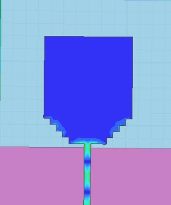
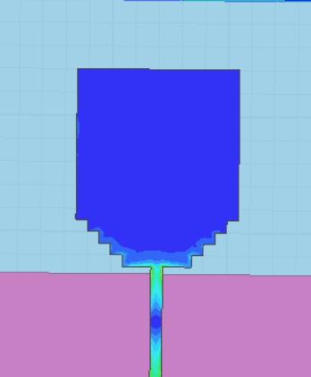
Thegapdistancebetweenthepatchandtheflooriscrucial for impedance matching. However, as the number of radiating parts increases, simply changing the ground plate’ssizetoalterthedistancebetweenthepatchandthe ground will not be sufficient to modify the impedance matching of the entire antenna. Therefore, this paper improvesthegroundingplate
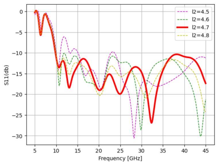
Figure 6: Effectsofgroundplatewidthl2onantenna impedancematching.
Figure 6 shows that the effect of changing the ground plane width l2 on the impedance matching in the frequency range of 17GHz–23GHz is relatively minimal when no slot is created. After carving a tiny rectangular groove on the ground plate, the distributed capacitance and distributed inductance are modified to provide the band-pass characteristic in the aforementioned frequency range.
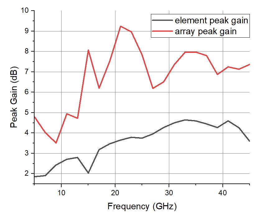
Figure 7:SimulationresultsofUWBunitandarraypeak gain.
The size of the optimized array antenna is 36mm×30mm. ThecomparisonofthemaximumgainoftheUWBantenna unitandarrayateachfrequencyisshowninFigure7
International Research Journal of Engineering and Technology (IRJET) e-ISSN: 2395-0056
Volume: 11 Issue: 04 | Apr 2024 www.irjet.net p-ISSN: 2395-0072
element spacing and feeder width are adapted, and the defective ground structure is used to adjust and optimize the performance of the array. As a result, the maximum gain of the ultra-wideband antenna array at 10GHz, 17GHz, 24GHz, 31GHz, and 38GHz reaches 4.45dBi, 7.30dBi,9.55dBi,8.07dBi,and6.26dBirespectively,which is a significant improvement compared to ultra-wideband unitsexhibitinggoodperformance.
Table -2: MaximumGainofUWBarrayantenna
AsshowninTable2,themaximumgainoftheUWB array antenna at 11.3GHz, 23GHz, 30.8GHz, and 40GHz is significantly higher than that of the radiation unit. The antenna achieves the effects of increasing gain and enhancing directivity. Meanwhile, in the design of the array, there are two ways to feed the array elements. The radiating elements are directly connected by the series feeder and the corner feeder, which reduces the antenna sizeandrealizestheantenna’sminiaturizationdesign.
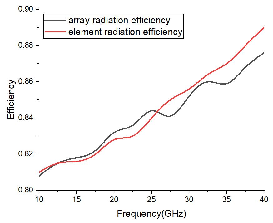
Figure 8: Radiationefficiencyofantennaunitandarray.
Figure8showstheradiationefficiencyoftheantennaunit andthearray,bothofwhichareintherangeof0.8-0.9.
This paper describes the design process of planar UWB antenna arrays. The UWB antenna unit is designed first. Theantennaunit’sbandwidthisincreasedfrom10–20GHz to10–45GHzbyloadingmultilevelstepsonaconventional rectangular microstrip patch and altering the current distribution at the patch’s edge. The UWB elements are then assembled into arrays. The array uses a series feed mode longitudinally and the corner feed method transversely. The longitudinal and transverse array
J. Xu, W. Hong, Z. H. Jiang, and H. W. Zhang, “Low-profle patch array antenna with corporate stacked microstrip and substrate integrated waveguide feeding structure,” IEEE Transactions on Antennas andPropagation,vol.67,no.2,p.6,2019.
J.Xu,W.Hong,Z.H.Jiang,H.Zhang,andK.Wu,“Lowprofle widebandverticallyfoldedslottedcircularpatcharray for ka band applications,” IEEE Transactions on Antennas and Propagation, vol. 68, no. 9, pp. 6844–6849,2020.
Y. Li and K.-M. Luk, “60-GHz substrate integrated waveguide fed cavity-backed aperture-coupled microstrip patch antenna arrays,” IEEE Transactions onAntennasandPropagation,vol.63,no.3,pp.1075–1085,2015.
M.Khalily,R.Tafazolli,P.Xiao,andA.A.Kishk,“Broadband mm-wave microstrip array antenna with improved radiation characteristics for diferent 5G applications,” IEEE Transactions on Antennas and Propagation, vol. 66, no. 9, pp. 4641–4647, 2018. R. Nicole, “Title of paperwithonlyfirstwordcapitalized,”J.NameStand. Abbrev.,inpress.
M. Majidzadeh, C. Ghobadi, J. Nourinia, and J. Poorahmadazar, “Small monopole antenna with modifed slot ground plane for UWB applications,” in Proceedings of the 20th Iranian Conference on Electrical Engineering (ICEE2012), pp. 1078–1082, IEEE,Tehran,Iran,May2012.
S. Ahmad, U. Ijaz, S. Naseer et al., “A jug-shaped CPW-fed ultra-wideband printed monopole antenna for wireless communications networks,” Applied Sciences,vol.12,no.2,p.821,2022.
N. Mishra and S. Beg, “A miniaturized microstrip antenna for ultra-wideband applications,” AEM, vol. 11, no. 2, pp.54–60,2022.
T. Varum, J. Caiado, and J. N. Matos, “Compact ultrawideband series-feed microstrip antenna arrays forIoTcommunications,”AppliedSciences,vol.11,no. 14,p.6267,2021.
International Research Journal of Engineering and Technology (IRJET) e-ISSN: 2395-0056
Volume: 11 Issue: 04 | Apr 2024 www.irjet.net p-ISSN: 2395-0072
Z. Fang, H. Yang, Y. Gao et al., “Design of a 2-bit reconfgurable UWB planar antenna array for beam scanning application,” IEEE Open Journal of Antennas andPropagation,vol.4,pp.91–96,2023.
V.-T. Nguyen and J.-Y. Chung, “Design of a planar antenna array with wide bandwidth and narrow beamwidth for IR-UWB radar applications,” Applied Sciences, vol. 12,no.17,p.8825,2022.
M. Garbaruk, “A planar four-element UWB antenna array with stripline feeding network,” Electronics, vol. 11, no.3,p.469,2022.
H. Zu, B. Wu, P. Yang, W. Li, and J. Liu, “Wideband and highgain wearable antenna array with specifc absorption rate suppression,” Electronics, vol. 10, no. 17,p.2056,2021.
S. Ahmed, T. Kim Geok, M. Y. Alias et al., “A UWB antenna array integrated with multimode resonator bandpass flter,”Electronics,vol.10,no.5,p.607,2021.
Y.Wang,F.Zhu,andS.Gao,“Designandimplementationof connected antenna array for ultra-wide applications,” Progress in Electromagnetics Research C, vol. 58, pp. 79–87,2015.
Y. K. Choukiker, S. K. Behera, and S. K. Sharma, “Two and four-element wideband sectoral fractal array antennaswithomni-directionalradiationpatterns,”in Proceedings of the 2013 IEEE Applied Electromagnetics Conference (AEMC), pp. 1-2, Bhubaneswar,India,December2013.
Y.-Y. Yang and Q.-X. Chu, “Planar 4-element UWB antenna array and time domain characterization,” Microwave and Optical Technology Letters, vol. 50, no. 12, pp. 3118–3123,2008.
H.-Z. Liu, J. C. Coetzee, and K. Mouthaan, “UWB antenna array for wireless transmission along corridors,” MicrowaveandOpticalTechnologyLetters,vol.50,no. 4,pp.886–890,2008.
Q. Tan, K. Fan, Y. Yu, C. Yin, and G. Luo, “Ultra-wideband planarpatchantennaarrayusingmultimoderesonant antenna element for millimeter-wave applications,” MicrowaveandOpticalTechnologyLetters,vol.65,no. 1,pp.320–327,2023.
B.R.Shookooh,A.Monajati,andH.Khodabakhshi,“Teory, design, and implementation of a new family of ultrawideband metamaterial microstrip array antennas based on fractal and Fibonacci geometric patterns,”JElectromagnEngSci,vol.20,no.1,pp.53–63,2020.
B. Rezaei Shookooh, A. Monajati, and H. Khodabakhshi, “Ultra-wideband metamaterial-loaded microstrip array antennas using Fibonacci & fractal geometric patterns, design and modelling,” EJECE, vol. 4, no. 5, 2020.
N. Jaglan, S. D. Gupta, E. Takur, D. Kumar, B. K. Kanaujia, and S. Srivastava, “Triple band notched mushroom and uniplanar EBG structures based UWB MIMO/diversity antenna with enhanced wide band isolation,” AEU International Journal of Electronics andCommunications,vol.90,pp.36–44,2018.
N.Jaglan,S.D.Gupta,B.K.Kanaujia,andM.S.Sharawi,“10 element sub-6-GHz multi-band double-T based MIMO antennasystemfor5Gsmartphones,”IEEEAccess,vol. 9,pp.118662–118672,2021.
N. Jaglan, S. D. Gupta, and M. S. Sharawi, “18 element massive MIMO/diversity 5G smartphones antenna design for sub-6 GHz LTE bands 42/43 applications,” IEEE Open Journal of Antennas and Propagation, vol. 2,pp.533–545,2021.