
International Research Journal of Engineering and Technology (IRJET) e-ISSN: 2395-0056
Volume: 11 Issue: 04 | Apr 2024 www.irjet.net
p-ISSN: 2395-0072
DESIGN OF CIRCULAR VOLUMETRIC ANTENNA USING SIW TECHNOLOGY FOR WIRELESS APPLICATIONS
Supriya K1, Durga Lalitha K2, Phanindra M3, Pavan G4, Sasidhar A5, Ramprasad Ravula6
12345Graduate Student,6Senior Assistant Professor Department of Electronics and Communication Engineering, Sri Vasavi Engineering College, Tadepalligudem, West Godavari, Andhra Pradesh, India.
Abstract –Single band circular volumetric antenna using Substrate Integrated Waveguide (SIW) technology is introduced The volumetric antenna is made ofFR4 (Flame Retardant) substrate material and antenna’s circular patch has a radius of 4 mm. By placing a rectangular slot on the circular patch with 8 mm length and 0.4 mm width, the HFFS antenna simulation tool analyses the reported antenna properties and harvesting the results such as gain of 3 dB, directivity of 4.21 , VSWR of 1.31 and return loss of17.22 dB at frequency of 10.75 GHz. The proposed circular volumetric SIW antenna structures come up with a bandwidth of 210MHz. It is widely used in radar systems, remote sensing and microwave imaging applications.
Keywords: Radio Frequency, SIW Technology, Volumetric antenna,WirelessCommunicationSystems.
1. INTRODUCTION
Antennas are crucial components of wireless communication networks. An antenna is, by definition, a devicethatconvertsanelectromagneticwaveinfreespace fromanRFsignalthatistravelingonaconductor[1].Lowprofile antennas are necessary in high-performance aircraft, spacecraft, satellite, and missile applications where aerodynamic profile, size, weight, cost, performance, and ease of installation are constraints. Similar standards are currently found in a wide range of other commercial and government applications, including wireless communications and mobile radio. It is possible tousemicrostripantennastosatisfytheseneeds[2] Micro strip components require strict fabrication concessions when implementing RF, microwave and millimeter-wavecomponents,yettheyworkquitewellfor low frequency applications. At higher frequencies, however, they become ineffective. This is because at higher frequencies, wavelengths are shorter. Conversely, waveguide devices are perfect for higher frequency systems,buttheyareveryexpensive,difficulttomakeand difficulttocombinewithnearbyplanarcomponents. The design of effective circuits and parts that operate in the radio frequency (RF) and microwave frequency spectrumnowhasmoreoptionsthankstothistechnology. SIW bridges the gap between planar transmission line technologies, such as the micro strip, and traditional airfilled rectangular waveguide [3]. The authors presented a
platform for integrating all the components of a microwave circuit inside a single substrate, with a rectangular cross-section. Using a single substrate guarantees a limited volume and simplicity of manufacture, while the rectangular cross-section of the lineprovidestheadvantagesofthewaveguidetopologyin terms of losses [4] One attraction to SIW is that the amount of metal that carries the signal is far greater than itwouldbeinmicrostrip[5].
2. SUBSTRATE INTEGRATED WAVEGUIDE
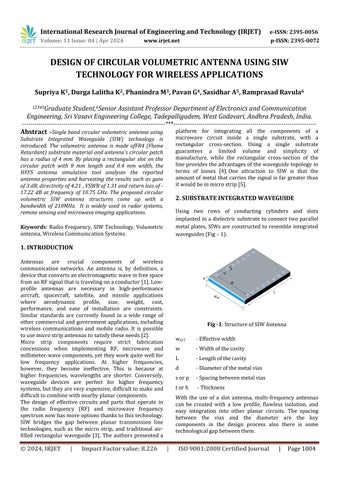
Using two rows of conducting cylinders and slots implantedina dielectricsubstratetoconnecttwoparallel metal plates,SIWsareconstructedtoresembleintegrated waveguides(Fig–1).
wef f -Effectivewidth
w -Widthofthecavity
L -Lengthofthecavity
d -Diameterofthemetalvias
sorp -Spacingbetweenmetalvias
torh -Thickness
With the use of a slot antenna, multi-frequency antennas can be created with a low profile, flawless isolation, and easy integration into other planar circuits. The spacing between the vias and the diameter are the key components in the design process also there is some technologicalgapbetweenthem.
International Research Journal of Engineering and Technology (IRJET) e-ISSN: 2395-0056
Volume: 11 Issue: 04 | Apr 2024 www.irjet.net

Fig -2:Technologicalgapbetweenthemicrostrippatch andwaveguides
The following formula should be used to compute them. ThepropagationinsideaSIWiscomparabletothatinside atypicalhollowwaveguide,withafewnotableexceptions. The propagating modes resemble the TEn0 mode of the waveguideandareattheTE10 fundamentalmode.Thesize of a SIW and an efficient waveguide with continuous lateralwallsarerelatedbyseveralkeyformulas. Due to the similarities between the two types of waveguides, it has been discovered that there are empiricalcorrelationsbetweenthedimensionsofthe SIW and the effective width (‘weff ’) of the rectangular shape waveguide with the same propagation parameters. These correlations allow for the early design and dimensioning of SIW components without the need for full-wave analysis methods. A relationship found in the design equationis
where ‘d’ is the diameter of the metal vias, ‘w’ signify widthofthecavity,‘weff ’denoteseffectivewidthoftheSIW and‘s’showsspacingbetweenthevias(Fig-1).
2395-0072
are small enough. It is possible to empirically determine theviasspacing(s)asafunctionofdiameter(d). <2.5 (3)
The modes of propagation can be calculated using the empiricalequation(4)
Radiation losses are minimized when the vias diameters are large enough and their separations from one another
Wherecisthelightvelocityinfreespace,LandWarethe cavity's length and width, m = 1, n = 1 and s = 0 for the fundamental mode (TE110), and εr is the dielectric substrate'srelativepermittivity.Consequently,SIWdesign structures show propagation characteristics similar to rectangular waveguides when the metal vias are closely spacedapartandradiationlossesareconsidered.
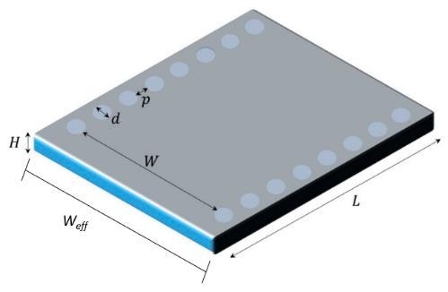
2.1 Antenna Design Flow Chart
-3:PictorialRepresentationofAntennaDesign
International Research Journal of Engineering and Technology (IRJET) e-ISSN: 2395-0056
Volume: 11 Issue: 04 | Apr 2024 www.irjet.net p-ISSN: 2395-0072
Theaboveflowchartrepresentsthepictorial representationofproposedantenna.
2.2 Antenna Design Procedure using HFSS
Step 1
Adding the substrate (3D plane)in the Editor window.
Alignthesubstrateusingtheposition.
Assignthedimensionsofthesubstrate.
Step 2
Addingtheground(2Dplane)tothesubstratein theEditorwindow.
Alignthegroundusingtheposition.
Assignthedimensionsoftheground.
Step 3
Adding the patch (2D plane) to the substrate in theEditorwindow.
Alignthepatchusingtheposition.
Assignthedimensionsofthepatch.
Design the specific shapes by using unite or subtractoptionsinthemenubar.
Step 4
AddPortmaterialtothesubstrate.
Align the material such that it should contain X andZaxisonly.
Assignthedimensionsandposition.
Step 5
Nowaddtheboundariesforthepatchandground.
Rightclickonthepatchineditorwindow>>Goto AssignBoundary>>SelectPerfectE>>Clickok.
Repeatsameforthegroundmaterial.
Step 6
NowaddtheExcitationtotheport.
Rightclickontheportineditorwindow>>Goto Assign Excitation>> Select Lumped Port >> Click onNext>>SettheIntegrationlinetoNewLine>> Nowdrawalinefromgroundtopatch.
Step 7
Now go to the project manager and right click on theAnalysis.
Step 8
Nowfromthemenubargotosimulationoption.
Click on validate, If all the steps in the validation showsgreenmark thengotonext stepotherwise correctthemistakesintheparticularsection.
AftertheValidationstepclickonAnalyseAll.
Step 9
Then will notice some messages in the progress andMessageManagerWindow.
After noticing” Normal completion of simulation onserver:Localmachine”messageinthemessage manager window you can generate the reports from the results section in project manager window.
Step 10
Togeneratetheresults.
Right click on Results >> Create Modal Solution Data Report >> Rectangular Plot >> Select the RequiredParameter>>ClickontheNewReport.
AfterinsertionofInfinitesphere,wecansimulate thegainanddirectivity.
Right click on Results >> Create Far Field Report>>RectangularPlot>>SelecttheRequired Parameter>>ClickontheNewReport.
3. DESIGN OF PROPOSED ANTENNA
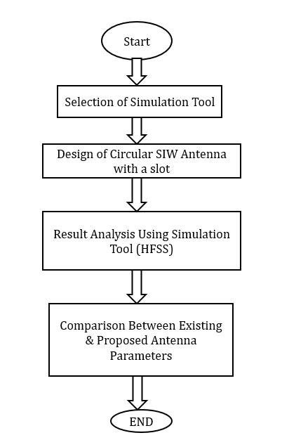
This design consists of bottom as ground plane with substrate and top ofcircular patch Which areincommon having some cylindrical holes along the patch with some specified measurements called as vias or holes. Vias play the vital role in the radiation of the signal for an SIW antenna.
3.1 Antenna Configuration

(i)
Add Solution Setup >> Click on Auto >>Set the Distribution to Linear Step >> Assign the Start, EndandStepSizeFrequency>>ClickOk.
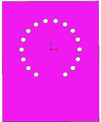
(i)TopView (ii)BottomView
Fig -4:Geometryoftheproposedantenna
International Research Journal of Engineering and Technology (IRJET) e-ISSN: 2395-0056
Volume: 11 Issue: 04 | Apr 2024 www.irjet.net p-ISSN: 2395-0072
Table -1: Dimensionsoftheproposedantenna
Parameters
Values (in mm)
Lengthofthesubstrate(Lsub) 20
Widthofthesubstrate(Wsub) 25
Feedlength(lf) 11
Feedwidth(wf) 2
Gapbetweenfeedtopatch(gm) 3
Radiusofcircularpatch(r) 7.5
Diameterofvias(d) 0.5
LengthoftheSlot(Ls) 8
WidthoftheSlot(Ws) 0.4
Heightofthesubstrate 1.6
3.2 Significance of Circular SIW Antenna with slot
To obtain the best results transverse slot cut is from the circular patch of the antenna, due to this slot the single frequencyisradiatedbyexcitingthefeedthroughtheport Thiscanbeseenthroughthefielddistributionpattern. To obtain the most accurate results is obtained by with and slotconsideration.Slotlengthof8mmandwidthof0.4mm hasharvesttheradiatingfrequency10.75GHzwithreturn lossof-17.22dB,gainis3dBandVSWRisalsointherange between1-2only.
Table -2: ParametricAnalysisbasedonwithandwithout slot
Parameters Without Slot With Slot

4.1 Return Loss
Bandwidth
4. RESULTS
The presented circular volumetric antenna with subtracted slot has been simulated using SIW technology by FR4 substrate. Accordingly observed the parameters using simulation tool Ansys HFSS. The simulated antenna topandbottomviewrepresentedintheFig-5.

Fig -6:ReturnLoss
From the above graph is clearly noticed that with slot circularSIWantennaobtainedat10.75GHzwith-17.22dB return loss. Whereas without slot consideration it’s not radiating below -10dB.Accordingly more radiation losses arepresent.
International Research Journal of Engineering and Technology (IRJET) e-ISSN: 2395-0056
Volume: 11 Issue: 04 | Apr 2024 www.irjet.net p-ISSN: 2395-0072
4.2 Voltage Standing Wave Ratio

Fig -7:VoltageStandingWaveRatio
TheacceptableVSWR valueis above1and below2.From the above plot VSWR value is 1.31 at 10.75GHz without slot of circular SIW antenna. But with slot consideration VSWR is greater than 2, therefore more reflections are takesplace
4.3 Bandwidth

Fig -8:Bandwidth
The bandwidth of an antenna refers to the range of frequencies over which the antenna can operate the bandwidth for this antenna is about 210MHz (10.86GHz10.65Ghz).whichis obtainedthef1at 10.65GHzandf2 at 10.86GHz.
4.4 Three Dimensional Gain without slot


Fig -9:Gainwithoutslot
The acceptable range of gain for an antenna is from 3 dB, and for this simulated antenna obtained the gain of -3dB initiallywithoutslot. Thisisnotconsiderableforpractical applications.
4.5 Three Dimensional Gain Plot

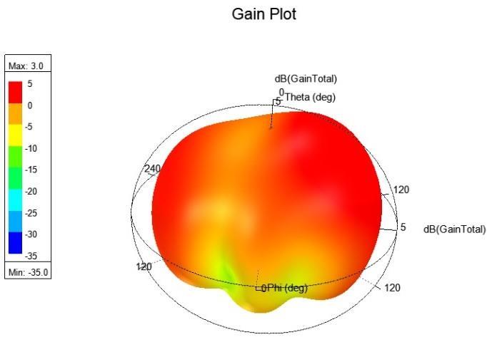
Fig -10:Gainwithslot
Thegainobtainedafterplacingaslotfortheantennawith specific dimensions is 3dB, which is the required gain for anypracticalantenna.
International Research Journal of Engineering and Technology (IRJET) e-ISSN: 2395-0056
Volume: 11 Issue: 04 | Apr 2024 www.irjet.net p-ISSN: 2395-0072
4.6 Electric Field Distribution

Fig -11:ElectricFieldDistributionplot
This diagram shows the Electric Field Distribution of the simulated antenna particularly on circular SIW antenna with slot section. The majority of the E-Field can be observedatslotandedgesofthepatch
4.7 Current Distribution
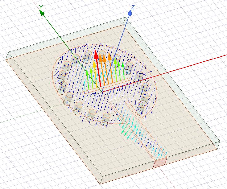
Fig -12:CurrentDistributionplot
The Current Distribution is also high around the slot and theedgesofthepatchanditislowaroundtheviasregion.
4.8 Three Dimensional Directivity plot
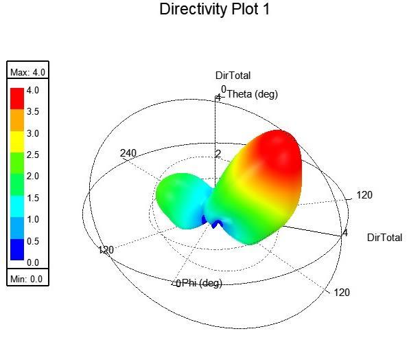
Fig -13:Directivityplot
TheDirectivityofthesimulatedantennaisaround4atthe resonatingfrequencyof10.75GHz.
Table -3: ComparisonwithexistingworkswithProposed work
Theproposedcircularvolumetricantennawithsubtracted slot provides better results. Significantly gain produced 3dB at respective resonating frequency 10.75GHz comparingwithref[6-10].
International Research Journal of Engineering and Technology (IRJET) e-ISSN: 2395-0056
Volume: 11 Issue: 04 | Apr 2024 www.irjet.net p-ISSN: 2395-0072
5. CONCLUSION
Initiallydesigned the circularvolumetric antenna without slotandthenplaceda slotwithlengthof 8mm&widthof 0.4mm. The acquired results are best for the volumetric antenna with slot and the results are taken out at 10.75GHzwith a return loss of-17.22dB.VSWR of 1.31 at 10.75GHz. Gain of 3 dB at 10.75GHz. Obtained bandwidth of 210MHz (10.86GHz-10.65GHz).This proposed antenna design can be used in Radar systems for target detection, Remote sensing applications such as weather monitoring, for 5G networks as SIW antennas can play a role in supportinghigh-frequencybands,andMicrowaveimaging for medical imaging systems such as microwave breast imagingforearlydetectionofbreastcancer
ACKNOWLEDGEMENT
This work carried out by Research and Development center,departmentofECE,SriVasaviEngineeringCollege, Tadepalligudem,WestGodavari,AndhraPradesh,India.
REFERENCES
[1] Constantine A. Balanis, “antenna theory analysis and design”,4thed.Wiley2016.
[2] Ramesh Garg, Prakash Bartia, Inder Bahl, ApisakIttipiboon, “Microstrip Antenna Design Handbook”,ArtechHouseInc2001.
[3] WaelAli,EhabHamad,MohamedBassiuny,Mohamed
Hamdallah, “Complementary Split Ring Resonator Based Triple Band Microstrip Antenna for WLAN/WiMAX Applications”, Radio engineering, Vol.26,No.1,pp.78-84,Apr.2017.
[4] Navneet Kumar, Neeraj Julka, “Star Shaped Multiband Antenna for Wireless Application”, International Journal of Advancement in Engineering Technology, ManagementandAppliedScience(IJAETMAS),Vol.04, pp.29-33,February.2017.
[5] Razin Ahmed and M. Fokhrul Islam, “Slotted Microstrip Patch Antenna for Multiband Application”, InternationalElectricalEngineeringJournal(IEEj),Vol. 5,No.3,pp.1293-1299,2014.
[6] Shalina Garg, Ratish Kumar,“Multiband Microstripn Patch Antenna Antenna for Wireless Applications using Metamaterial”, International Journal of AdvancedResearchinElectronicsandCommunication Engineering(IJARECE),Vol.4,Issue6,June2015.
[7] Ke Wu et.al, “Substrate Integrated Transmission Lines:Review and Applications”, IEEE Journal of Microwaves,vol.1,no.1,pp.345-363,January2021.
[8] Daniels et.al,“60 GHz wireless communications: emerging requirements and design recommendations”, IEEE Vehicle Technology Magazine,pp.41-50,2007.
[9] Gupta et. al, “Analysis and design of integrated circuit antennamodules”,(Wiley,NewYork,2000).
[10] Cassivi et.al, “Dispersion characteristics of substrate integrated rectangular waveguide”, IEEE Microwave Wireless Components Letters, vol. 12, pp. 333-335, 2002.Propagation & USNC/URSI National Radio ScienceMeeting,2018.
BIOGRAPHIES


Ms. Supriya K Final Year
B.Techstudentinthe Electronics & Communication Engineering Department at Sri VasaviEngineeringCollege Tadepalligudem,WestGodavari ,AndhraPradesh,India.
Ms. Durga Lalitha K Final Year
B.Tech student in the Electronics & Communication Engineering Department at Sri Vasavi Engineering College, Tadepalligudem,WestGodavari ,AndhraPradesh,India.
Mr.Phanindra M FinalYear
B.Techstudentinthe Electronics & Communication Engineering Department at Sri Vasavi Engineering College, Tadepalligudem,WestGodavari ,AndhraPradesh,India.
Mr. Yaswanth Pavan G Final Year B.Tech student in the Electronics & Communication Engineering Department at Sri VasaviEngineering College, Tadepalligudem,WestGodavari ,AndhraPradesh,India.
Mr. Sasidhar A Final Year
B.Techstudentinthe Electronics & Communication Engineering Department at Sri VasaviEngineering College,Tadepalligudem, WestGodavari,AndhraPradesh, India.
International Research Journal of Engineering and Technology (IRJET) e-ISSN: 2395-0056
Volume: 11 Issue: 04 | Apr 2024 www.irjet.net p-ISSN: 2395-0072

Ramprasad Ravula Completed hisM.Techin2009fromJNTUK, Kakinada, Andhra Pradesh. He has totally 15 Years of teaching experience. Presently he is workingasSr.Assistant Professor in the Department of Electronics and Communication EngineeringofSriVasavi EngineeringCollege, Tadepalligudem,WestGodavari ,Andhra Pradesh, India. His interested Research area is AntennassignificantlySIW Antenna