
International Research Journal of Engineering and Technology (IRJET) e-ISSN: 2395-0056
Volume: 11 Issue: 04 | Apr 2024 www.irjet.net p-ISSN: 2395-0072
International Research Journal of Engineering and Technology (IRJET) e-ISSN: 2395-0056
Volume: 11 Issue: 04 | Apr 2024 www.irjet.net p-ISSN: 2395-0072
Asst.Professor M D L Saranya1 , K Girivardan2 , A Dinesh3 , Ch Bangaru Talli4
1Head of Department, Dept. of EEE, Visakha Institute of Engineering & Technology, A.P, India
2Student, Dept. of EEE, Visakha Institute of Engineering & Technology, A.P, India
3Student, Dept. of EEE, Visakha Institute of Engineering & Technology, A.P, India
4Student, Dept. of EEE, Visakha Insti tute of Engineering & Technology, A.P, India
ABSTRACT – The variable frequency power electronic systemdesign is havinga great importance invarious types of industrial applications. To fulfill those requirements of variable frequency, cycloconverters are widely used. Cycloconverter is a power electronics device which converts input power at one frequency into output power at different frequency.
The firing angles are carefully timed to regulate the output frequency. Thyristors are used as the switching devices in the cycloconverter. Thyristors are triggered to control the output waveform. The output voltage waveform, frequency, and magnitude can be observed as the model changes the firing angles and load conditions.
Key Words: Converter, Single phase cycloconverter, Simulation, power electronic circuit, variable frequency converter, waveforms, Parameters for R load
1.INTRODUCTION
Acycloconverterconvertsaconstantvoltage,constant frequencyACwaveformtoanotherACwaveformofa lowerfrequencybysynthesizingtheoutputwaveform fromsegmentsoftheACsupplywithoutanintermediate DCLink
Therearetwomaintypesofcycloconverters:
1)Blockingmodetype
2)Circulatingmodetype
Whentheloadcurrentispositive,thepositiveconverter suppliestherequiredvoltage,andthenegativeconverteris blocked. Suppose if the load current is negative, then the negative converter supplies the voltage and the positive converterisblocked.Thisoperationiscalledblockingmode operation.
Bychance,ifbothconvertersareenabled,thenthesupply willbeshort-circuited.Toavoidthis,anintergroupreactor (IGR)mustbeconnectedbetweentheconverters.Ifboththe converters are enabled, then a circulating current is produced.Thisisunidirectionalbecausethethyristorsallow the current to flow in only one direction. The cyclo convertersusingthisapproacharecalledcirculatingcurrent converters.
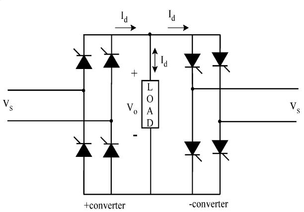
Inthebelowcircuitweareusingdifferentblockssuchas Power Gui, AC Voltage source, Frequencycontrol , Logical controller,InputVoltage,UniversalBridgePconverterandN converter, R Load, Voltage measurement, Root mean square(RMS),Scope,Display.
GUI standsforGraphicalUserInterface.Thisblockstores the equivalent Simulink circuit that represents the state spaceequationsofthemodel.Byusing AC Voltage source supplywecansupplyACpowertothecircuit.Hereweare using230v,50Hzsupply. Frequency Control isimportant formaintainthefrequencyofthevoltageandpowerbalance. NOT Gate isusedasLogicaloperatorinthiscircuit.Itisact like as a switch. Universal Bridge block is the important blockinthecircuit.Theuniversalbridgeblockimplementsa universalthree-phasepowerconverterthatconsistofupto six power switches connected in a bridge configuration. The RMS blockstandsforRootMeanSquarevalueofeach roworcolumnoftheinput,oralongvectorsofaspecified dimensionoftheinput.WeareusingRloadinthiscircuit.
Volume: 11 Issue: 04 | Apr 2024 www.irjet.net
Scope isusedtoobservetheoutputofagivencircuitandthe Display can show the reading of the circuit.
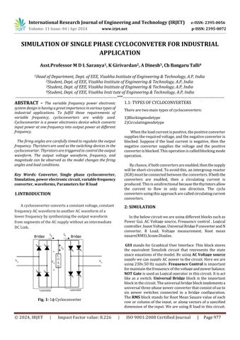
Simulatedofsinglephasecycloconverterbyusingsimulation toolisshowninFig2.Twouniversalbridgeconvertershas beenconnectedinantiparallelnamed`P’converterand`N’ converterwithacommonload.
ThissimulationisperformedtoFixedinputfrequency into varied frequency. Hence in order to obtain desired outputfrequency,thecircuitisdesignedinsuchawaythat forDuringthePositivehalf-cycleoftheinputwaveform,the UniversalBridgePConverteroperatesbyLeadingthefiring ofitsthyristors,producinganoutputatafrequencyHigher thantheinputfrequency.
Duringthenegativehalf-cycleoftheinputwaveform,the UniversalBridgeNConverteroperatesbydelayingthefiring ofitsthyristors,producinganoutputatafrequencylower thantheinputfrequency.
The combined output of these converters, when connected to the load, results in an output voltage with a frequencydifferentfromtheinputfrequency.Theloadcan bea motororanydevicethatrequiresvariablefrequency control.
By controlling the firing angles of the thyristors in the Universal Bridge P and N Converters, you can vary the output frequency and control the speed or other characteristicsoftheconnectedload.
This basic model showcases the concept of cycloconversion by manipulating the firing angles of thyristorsduringeachhalf-cycleoftheinputACwaveform. In practice, more advanced control circuits and feedback systemsareusedtoachieveprecisefrequencycontroland regulation.
Table -1: Parameters
SnubberCapacitance(Cs) Inf
3.OUTPUT
Ifweobserveatthescopewecangetfouroutputs.Those areInputsupply,outputsupply,outputfromUniversalbridge PconverterandUniversalBridgeNconverter.
Theinputsupplyvoltageat230Volts(rms)at50Hzhasbeen converted.Thesupplyvoltagewaveformof50HzforRload isshowninFig.3
For 10 Ω purely resistive load (R Load), current flowing through it has been 23 amperes. Since current is in phase withvoltageforresistiveload,anidentical waveshapesof currentandvoltagewaveformsexcepttheirmagnitudeshas been obtained. highlights the output voltage and current waveformsrespectivelyforRloadattheoutputfrequency.


4:OutputWaveformofNConverter
International Research Journal of Engineering and Technology (IRJET) e-ISSN: 2395-0056
Volume: 11 Issue: 04 | Apr 2024 www.irjet.net p-ISSN: 2395-0072
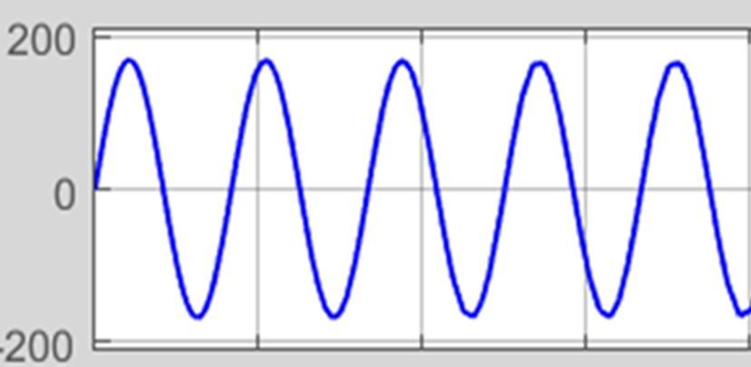
Fig 5:InputWaveform
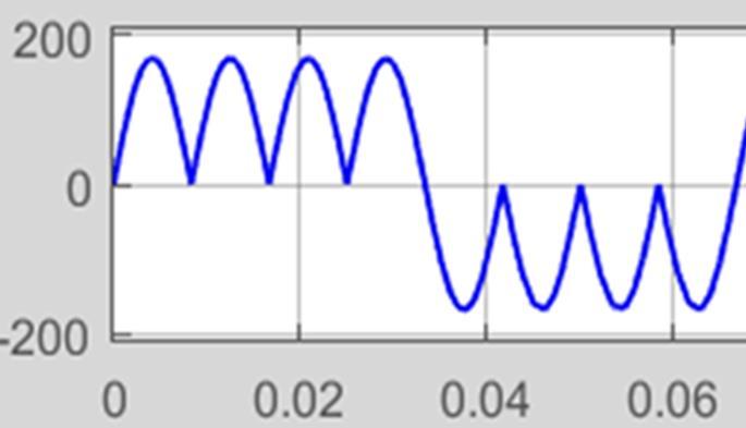
Fig 6:OutputWaveformforRLoad
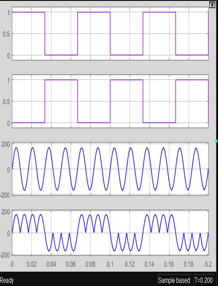
Fig 7:OutputWaveformforRLoad
Theabovefig3,4,5,6,7showtheoutputwhichareconnected tothescope.Fig3showstheoutputofUniversal bridgeP converterduringthepositivehalfcycleFrequencycontrol supplies additional frequency to the universal bridge P converterbyusinglogicaloperatorNotgate.HereNotgate workslikeaninverterorswitch.Duringpositivehalfitisin
on condition and supply frequency control supply to Universal bridge P converter hence we can get high frequencythantheinputfrequency.
Fig4showstheoutputofNconverterduringthenegative UniversalbridgeNconverterisonstateandPconverteris Offstateandlogicaloperatorisalsoinoffstate.Theoutputof Nconverterislessthantheinputfrequency
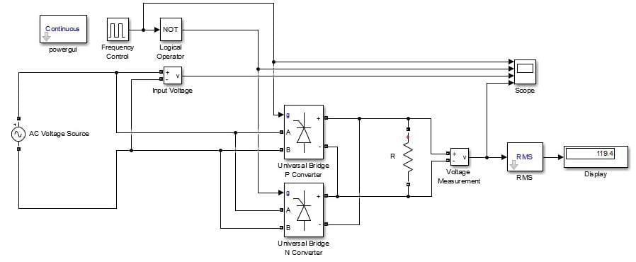
Fig5showstheInputsupplyhereweareusing230v,50Hz, ACsupplyandthepeakamplitudeis162.2.
Fig6showstheOutputwaveformofCycloconverterwecan getthisoutputbycombiningtheoutputofuniversalbridgeP converteranduniversalbridgeNconverteroutputtoRload by using R load we can get our required output power at differentfrequency.Wecanobservetheoutputatscopeand thereadingatdisplay.
The most important industrial applications of cycloconvertersarelistedbelow.
• Cementmilldrives
• Rollingmills
• Shippropulsiondrivers
• Waterpumps
• Washingmachines
• Minewinders
• Industries
5. CONCLUSIONS
A 1ϕ cycloconverter has been successfully simulated usingUniversal'P'bridgeConverter&`N’Bridgeconverter configurationwhichhasgeneratedanoutputvoltageata frequency than the input frequency for both R Load as desired. The hardware implementation of 1 Phase cyloconverters is proposed to validate the simulated results.Theseveralvitalapplicationsofthecycloconverter circuitconfigurationsforindustrialneedhavebeenstudied anddiscussed.Thesimulationresultshighlightingvoltage andcurrentwaveformsfoundsatisfactory.
1) D.KornackandP.Rakic,“CellProliferationwithout NeurogenesisinAdultPrimateNeocortex,”Science, vol.294,Dec.2001,pp.2127-2130,doi:10.1126/ science.1065467
2) M. Young, The Technical Writer’s Handbook. Mill Valley,CA:UniversityScience,1989.
3) capitalized,”J.NameStand.Abbrev.,inpress.
4) K.Elissa,“Titleofpaperifknown,”unpublished.