
International Research Journal of Engineering and Technology (IRJET) e-ISSN:2395-0056
Volume: 11 Issue: 04 | Apr 2024 www.irjet.net p-ISSN:2395-0072
International Research Journal of Engineering and Technology (IRJET) e-ISSN:2395-0056
Volume: 11 Issue: 04 | Apr 2024 www.irjet.net p-ISSN:2395-0072
C R Nikethan1, Ashwini V2
1P G Student
2
Professor, Dept. of Electronics and Communication Engineering, BMS College of Engineering, Karnataka, India
Abstract - The development of a cloud-connected infusionmonitoranditsdesignaredescribedinthisstudy. Infusiontherapyplaysacriticalroleinmodernhealthcare, requiring precise monitoring to ensure patient safety and optimal treatment outcomes. Traditional infusion monitors lack seamless connectivity and real-time data sharing, limiting their effectiveness in remote patient management and data analysis. To address this gap, we propose a novel infusion monitor that integrates sensors, data processing capabilities, and cloud connectivity. The monitor continuously measures infusion parameters such as flow rate, volume administered, and transmitting this data securely to a cloud-based platform. This enables healthcare providers to remotely monitor patients’ infusion sessions, receive real-time alerts, and access historical data for informed decision-making. The development process involves hardware design, sensor integration, data processing algorithms, and secure cloud communication protocols. The resulting cloud-connected infusion monitor offers enhanced patient safety, healthcare workflow optimization, and opportunities for data-driven insights into infusion therapy management. Thisinnovationhasthepotentialtorevolutionizeinfusion therapy by fostering greater collaboration between healthcare providers and improving patient care through intelligentandconnectedmonitoringsystems.
Key Words: Infusion Solution, Intravenous, Wireless Module,ESP8266,VisualStudio.
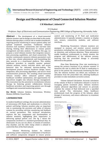
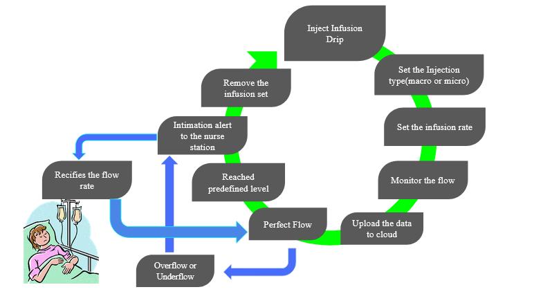
Inmodernhealthcaresettings,theaccurateadministration of intravenous (IV) fluids and medications is critical for patient well-being. Infusion monitors play an important role in maintaining the precision and safety of infusion systems by providing real-time monitoring and feedback on various parameters. This technical introduction explores the key components and functionalities of infusion monitors, highlighting their importance in delivering optimal patient care. The fig 1 shows the components involved in a standard gravitational drip. As showcased. As you can see above, it consists of container, drip chamber, and the roller clamp which is utilized to controltheflowofthefluidinduced.
Infusion Monitoring System: An infusion monitoring system comprises a combination of hardware and software components designed to ensure precise
control and monitoring of IV fluid and medication administration. It typically includes a monitor or display unit, sensors, connectivity modules, and software interfaces.
Monitoring Parameters: Infusion monitors are equipped to measure and monitor several essential parameters,includingflowrate,volumeinfused,pressure, air detection, and occlusion detection. These parameters enable healthcare professionals to closely monitor the progress and effectiveness of the infusion process, ensuring that the prescribed dosage is accurately deliveredtothepatient.
Flow Rate Monitoring: Flow rate monitoring is among the primary functions of an infusion monitor. It measures the rate at which the IV fluid or medication is given to the patient. By continuously monitoring the flow rate, the infusion monitor can detect any variations or deviations from the prescribed rate, allowing healthcare providerstotakeimmediatecorrectiveactions.
Volume Infused Calculation: Accurate calculation of the volume of fluid or medication infused is crucial in managing patient treatment plans. Infusion monitors employ advanced algorithms and sensors to precisely calculate the volume of fluid delivered over a specified time period. This information helps healthcare professionals track the progress of the infusion, adjust dosages if necessary, and ensure adherence to treatment protocols.
International Research Journal of Engineering and Technology (IRJET) e-ISSN:2395-0056
Volume: 11 Issue: 04 | Apr 2024 www.irjet.net p-ISSN:2395-0072
Pressure Monitoring: Pressure monitoring is essential to prevent potential complications during the infusion process. Infusion monitors are equipped using pressure sensors that detect and alert healthcare providers to abnormal pressure levels, such as occlusions or blockages in the IV line. By monitoring pressure, infusion monitors enhance patient safety by minimizing theriskofinfiltrationorextravasation.
Air and Occlusion Detection: Air detection and occlusion detection capabilities are critical features of infusionmonitors.Airdetectionsensorsenablethesystem to identify the presence of air bubbles in the IV line, triggering alarms and preventing potentially harmful air embolisms. Occlusion detection sensors monitor the pressure exerted on the IV line and alert healthcare providers to potential blockages orkinks, allowing for promptintervention.
Alarms and Notifications: Infusion monitors provide real-time alarms and notifications to healthcare professionals in the event of deviations from established parameters. These alerts prompt immediate attention, preventing errors, and facilitating timely intervention. Additionally, infusion monitors may offer connectivity options to send alerts to centralized monitoring systems or sync with the electronic health record (EHR) systems, facilitatingcomprehensivepatientcare.
Infusion monitors represent a crucial component inmedicalinfusionsystems,enablinghealthcareproviders toensureprecisionandsafetyduringtheadministrationof IV fluids and medications. By monitoring parameters such asflowrate,volumeinfused,pressure,anddetectingairor occlusions, these advanced monitoring systems enhance patientcareandcontributetoimprovedpatientoutcomes. Theintegrationofinfusionmonitorswithotherhealthcare technologies further streamlines care delivery and promotesefficienttreatmentpractices.
Theresearchsaysthattheerrorhappeningdueto infusion leads to death and it is placed in 3rd place for leading cause of death behind heart diseases and cancer. Around 4,40,000 deaths happen per year due to medical error. Around 60% of IV infusion contained one or more errors. So, to overcome all these errors the proposed systemwillbemorebeneficial.
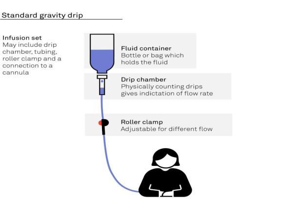
1.1 Calculation Flow rate:
DripfactorisgivenwhenwhatkindofIVsetwe use.TherearetwoIVsetsMicroandMacro.Microis60 gtt/mlandMacrois10,15,20gtt/ml.
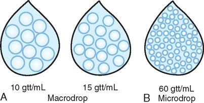

The prototype of my product is shown in fig 3 the processorandelectronicscomponentisplacedandfixedto the stand to make sure it is protected from theft. The detectionpatchisconnecteduptothedripchamberandit displays the details. The detection and processor is connectedbythewire.Oncethesensordetectsthechange it sends data to processor. The processor makes sure the required data is displayed in the device display and it is beingtransferredtocloud.Thereasonfortransferringdata to the cloud is to make sure to take responsibility for the errors(MedicoLegalpurpose).
International Research Journal of Engineering and Technology (IRJET) e-ISSN:2395-0056
Volume: 11 Issue: 04 | Apr 2024 www.irjet.net p-ISSN:2395-0072
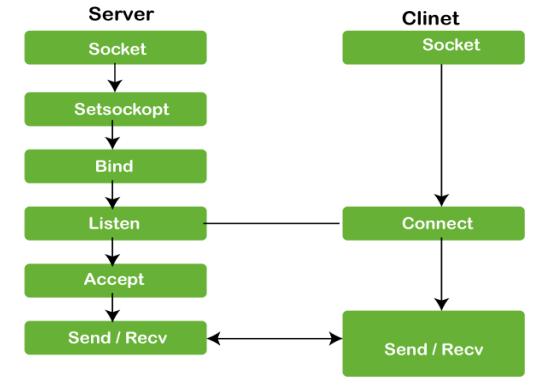
Socket Creation:
The process begins with the server creating a socket. A socket is a communication endpoint that allows dataexchangebetweendevicesoveranetwork.
Setsockopt:
After creating the socket, the server sets socket options.Theseoptionsconfigurevariouspropertiesofthe socket, such as its behavior and communication parameters.
Bind:
The server binds the socket to a specific address and port. This step associates the socket with a network interface and makes it ready to listen for incoming connections.
Listening:
Once bound, the server enters a listening state. It actively waits for incoming connection requests from clients.
Accepting Connections:
When a client initiates a connection, the server acceptstherequest.Thisestablishesaconnectionbetween theserverandtheclient.
Data Exchange:
With the connection established, both server and client can send and receive data through their respective socketsusingthe“Send”and“Receive”operations.
Client Side:
Socket Creation:
On the client side, a similar process occurs. The clientcreatesitsownsocket.
Connecting to Server:
Theclient initiatesa connection byspecifyingthe server’saddressandport.Itsendsaconnectionrequest.
Data Exchange:
Once connected, the client can also send and receivedatathroughitssocket.
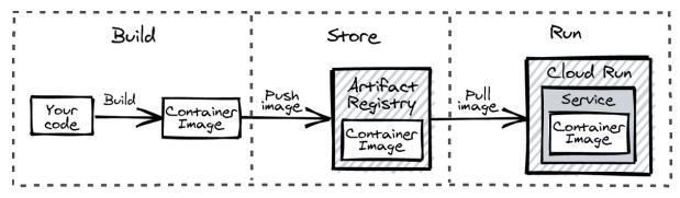
Build:
You start with yoursource code(depicted as “Your code”). This code is thenbuilt into a container image. The arrow labeled “Push Image” indicates that the built container image needs to bepushedto a storage location.
Store:
The “Artifact Registry Container Image” box representswherethepushedcontainerimagesarestored. Whenneeded,thestoredimagecanberetrievedfromthis registry.
Run:
The“CloudRunServiceContainerImage”box indicateswhereandhowthepulledcontainerimages areexecutedorrun.
International Research Journal of Engineering and Technology (IRJET) e-ISSN:2395-0056
Volume: 11 Issue: 04 | Apr 2024 www.irjet.net p-ISSN:2395-0072
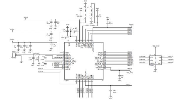
7. Circuit Diagram of ESP Wroom 32 Module
In the1ststageimplementing theconnection between the microcontroller and the sensor. In this stage interrupt is used to implement the connection. Once the code was uploaded there was lots of bounce happening. Timer interrupt was implemented to induce debounce. Implementation of RTC to cross verify the data received with the drop rate.Assigning GMTvalueandsetRTCtime manually.TogettheresultsgetTimeisusedtoreceivethe data at the output. Implementing client server communication. To understand the client-server communication, implement socket programming. Client is the microcontroller and server are another pc which is connected through the same LAN. Next step is to transfer data from client (microcontroller) to cloud through http protocol.
4.1 Output of sensor

Fig 8. Output of Sensor in Serial Monitor
The image presented above captures a moment when a successful socket programming connection was established. In this context, the Arduino serial monitor comes into play as it reveals the outcome of sensor data retrieval. Specifically, the displayed information includes the count, internal timer interrupt status, and RealTime Clock(RTC)data.Thisdata,aspertheimplementedcode, reflects the sensor's functioning and the synchronization withvarioussystem.
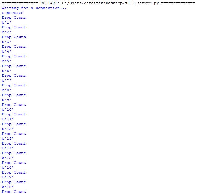
Fig 9. Output from the Server Side
International Research Journal of Engineering and Technology (IRJET) e-ISSN:2395-0056
Volume: 11 Issue: 04 | Apr 2024 www.irjet.net p-ISSN:2395-0072
Uponthesuccessfulestablishmentofsocketprogramming, theserversideentersa waitingstate,poisedtofacilitatea connection between the client and itself through the utilizationofportnumber80.Port80,awidelyrecognized standard, is predominantlyemployed for the transmission of data via the Hypertext Transfer Protocol (HTTP). The initiation of this connection is primarily driven by the use of the client's IP address, allowing for seamless communication between the two endpoints. This crucial interaction forms the backbone of web-based data exchange, enabling clients to request and receive web contenthostedontheserver.Theutilizationofport80and IP addressing underscores the fundamental principles of network communication, enabling the flow of information acrosstheinternetandtheWorldWideWeb.
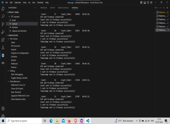
Following the successful establishment of the cloud connection, facilitated by the utilization of API keys and specifying the designated path for data transfer, the VisualStudio Code (VSCode) serial terminal provides a real-time display of sensor output data enriched with the essential comments incorporated in the codebase. This interactive terminal interface enhances the monitoring anddebuggingprocessfordevelopers.
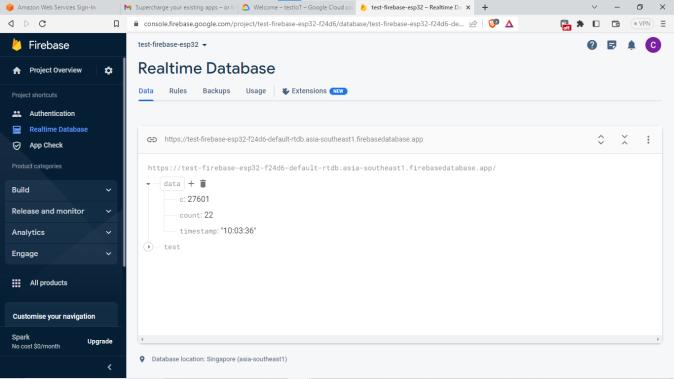
Withthemicrocontrollerseamlesslyconnectedto the cloud, the actual data transfer process commences. Image 11 vividly illustrates how this data is elegantly showcased within Firebase, a popular cloud database platform. Firebase serves as the conduit for storing, managing, andvisualizingthetransmitted data,rendering it accessible and organized for various analytics, applications, and downstream processes. This image captures the pivotal moment when the data integration between the microcontroller and the cloud takes shape, bridging the physical and digital realms and enabling a wide array of possibilities in the realm of IoT and datadrivenapplications.
TheCloudConnectedInfusionMonitordeveloped in this project offers significant benefits for healthcare delivery. By integrating infusion monitoring with cloud connectivity, we've improved patient safety through realtime data transmission and remote monitoring. This system enhances efficiency, scalability, and data management in healthcare settings. Moving forward, further advancements can expand its functionality and integration with existing systems to maximize its impact onpatientcare.
[1] K.R.Rani,N.Shabana,P.Tanmayee,S.Loganathan,and G. Velmathi, “Smart drip infusion monitoring system forinstantalertthroughnRF24L01,” ICNETS2,2017.
[2] A. Cataldo, G. Cannazza, N. Giaquinto, A. Trotta, and G. Andria, “Development of a remote system for realtime control of intravenous drip infusions,” IEEE, 2011.
[3] German, J.D., Mina, J.K.P., Alfonso, C.M.N., Yang, K.-H., “A study on shortage of hospital beds in the Philippinesusingsystemdynamics,” ICIEA,2018.
[4]T.L. Rodziewicz, and J.E. Hipskind, Medical Error Prevention. Treasure Island(FL): StarPearls Publishing, 2018.
[5] Design of Wireless Infusion Monitor Based on Bluetooth 4.0, Shilin Wanf School of Mechanical, Electrical and Information Engineering Shandong University Weihai, China, Baochen Jiang* School of Mechanical, Electrical and Information Engineering ShandongUniversityWeihai,China, IEEE,2018.