
International Research Journal of Engineering and Technology (IRJET) e-ISSN: 2395-0056 p-ISSN: 2395-0072
Volume: 11 Issue: 04 | Apr 2024 www.irjet.net
International Research Journal of Engineering and Technology (IRJET) e-ISSN: 2395-0056 p-ISSN: 2395-0072
Volume: 11 Issue: 04 | Apr 2024 www.irjet.net
MR.CH.Vijaya Shekhar babu1, Assistant Professor1
Reshma Dasari2 , N.siva sagar3 , B.sandeep4,C Bhanu prasad5
2345UG Students, Department of ECE, Krishna University College of Engineering and Technology, Machilipatnam, Krishna District, Andhra Pradesh
Abstract - Antennas are crucial components of wireless communication systems because they provide dependable signal transmission and reception. Printed dipole antennas have drawn a lot of interest because of their small size, cheap profile, andsimplicity ofproduction. The goal ofthis study is to improve the printed dipole antenna's performance so that it may be used in more wireless communicationapplications.
The goal of the optimization method is to improve important antenna characteristics including gain, bandwidth, radiation pattern, and impedance matching through thorough study and design considerations. Advanced simulation techniques are used to precisely simulate the antenna construction and forecast its performance characteristics. These approaches include the method of moments (MoM) and the finite element method (FEM). Several optimization techniques are investigated, including feeding methods, substrate selection, and geometrical adjustments. Through simulation studies, the effects of various factors, including substrate dielectric constant, dipole width, length, and spacing, on antenna performance are methodically examined. In addition, practical aspects like manufacturing limitations and environmental influences are taken into account to guarantee the viability and dependability of the optimized antenna design. To verify the simulation results, printed dipole antenna prototypes that have been optimized are constructedandtestedexperimentally.
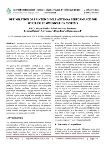
The role of microstrip patch antennas in modern wireless communication systems is growing. Antennas come in a variety of forms; some of the more common ones include parabolic reflectors, patch antennas, slot antennas, and folding dipole antennas. Every type of antenna has a distinct setofqualitiesanda specific use. Itis possible to
argue that antennas form the foundation of almost everything in wireless communication, without which the modern world would not have progressed to this point in technological advancement. These days, radio frequency (RF) and wireless communication technologies are extensivelyusedinmanyindustrialapplicationsaswellas daily human activities. In recent years, a plethora of wireless communication technologies have emerged, such as wireless broadband, wireless local area networks, and wireless interoperability for microwave access. Although themicrostrippatchantennahasarestrictedbandwidth,a disordered radiation pattern, and weak gain, it is an excellent fit for RF communication system demands. Because of the wide range of wireless applications, this issue has attracted the attention of scientists and researchers. The idea of a microstrip patch antenna, a novel electrical technology that may be manufactured on printed circuit boards, has been reported by several researchers. In today's wireless communication systems, theyarecrucial.TheLatinword"antenna"isthesourceof the word "antenna." "A component of a transmitting or receiving system designed to radiate or receive electromagnetic waves" is how the IEEE defines an antenna. Using a conventional microstrip manufacturing method,creatingmicrostripantennasisquiteeasy.Lower efficiency results from designing a small microstrip patch antenna with a substrate that has a higher dielectric constant.Applicationsforfifth-generation(5G)technology are expanding quickly in the current era of technology. It may offer a wide range of services, including remote industrial equipment control and medical care. Additionally, it ensures security and advances a nation's economicprogressbyimprovingsocietalsafety.
Well, there are a few reasons why 5G is superior to 4G. A primary benefit is the increased upload and download speeds. The speed at which 5G can download and upload
International Research Journal of Engineering and Technology (IRJET) e-ISSN: 2395-0056 p-ISSN: 2395-0072
Volume: 11 Issue: 04 | Apr 2024 www.irjet.net
filesmakesitmoreconvenient foroperations likesharing hugefilesorwatchinghigh-definitionfilms.Lowerlatency, orlessdelayindatatransmission,isanadditionalbenefit. This is particularly significant for real-time applications where a quicker reaction time is essential, such as video calls or gaming. Furthermore, 5G may be able to accommodate more connected devices concurrently withoutcompromisingspeed.Fortheexpandingnumberof IoTdevicesandsmarthometechnologies,thisisexcellent news.
Designing and simulating printed antenna design for 5G wireless communications is the goal of this thesis. Using the commercial tool HFSS, an antenna with wide band propertiesisdevelopedandsimulated.
1.3 Methodology
Usingdesignconsiderationsandmethods,anantennais createdforthedesiredfrequencyrange.
CreateanHFSSmodelfortheantenna.
Modelingandrefiningdesignparameters.
2. Literature review
In the age of wireless communication networks, patch antennas play a critical role in meeting various needs. A microstrip patch antenna may be constructed using a relatively simple technique that makes use of a more widelyknownmicrostripmanufacturingprocess.Although the patch may be set up in any way possible, the most popular configurations are circular and rectangular. For thewidestvarietyofapplications whicharealsothemost demanding these patch antennas are used in the most straightforwardmannerconceivable.Thetechnicalworkof severalstudiesonmicrostrippatchantennasisincludedin thispart.Thisarticle[8]suggestsabroadbandrectangular patch antenna that may be utilized for upcoming 5G wirelessapplications.WithS11valuesoflessthan -15dB, the proposed antenna for 5G communication achieves a broadband impedance bandwidth of higher than 67 percent (from 39GHz to 44GHz). The achieved bandwidth is enough to cover the 28 and 38 GHz bands of the upcoming 5G network. Except for the rejected band, the proposed antenna has almost omnidirectional patterns, a comparatively flat gain, and high radiation efficiency throughoutthefrequencyrange.Inthisinvestigation,With the use of slotting techniques with favorable return loss, favorable gain, and VSWR less than 2, the suggested antennawasabletosuccessfullyresonateatthreedistinct
frequencies: 31 GHz, 34.2 GHz, and 38.4 GHz. This is a useful notion for rapid internet access and wireless connectionestablishment.
Utilizing the well-known Microsoft Windows graphical user interface, HFSS is a powerful full-wave electromagnetic (EM) field simulator for arbitrary 3D volumetric passive device simulation. Its easy-to-learn framework combines solid modeling, automation, simulation, and visualization to provide fast and accurate solutions for your 3D electromagnetic challenges. With Ansoft HFSS, you can solve any 3D EM issue with unmatched performance and understanding thanks to the Finite Element Method (FEM), adaptive meshing, and stunning visuals. Fields, resonance frequency, and SparametersmayallbecomputedusingasoftHFSS.
Thereareseveral ways toplotdata.Whilewemayplot in 3D as well, 2DCartesian charting is the most commonly used format. Enumerated here are all the quantities that are plottable on different graphs. Consult the online assistanceforexplanationsofeachofthesequantities.
Eigenmode solution
Eigenmode Parameters (modes)
DrivenModalSolutionS-parameters
Y-parameters
Z-parameters
VSWR
Gamma(complexpropagationconstant)
PortZo
DrivenTerminalSolution
S-parameters
Y-parameters
Z-parameters
VSWR
Power(atport) VoltageTransformmatrix(T)
TerminalPortZo
Fields
Mag_E
Mag_H
Mag_Jvol
Mag_Jsurf
ComplexMag_E
ComplexMag_H
ComplexMag_Jvol
ComplexMag_Jsurf
Local_SAR(SpecificAbsorptionRate)
Types of Plots:
RectangularPlot
PolarPlot
International Research Journal of Engineering and Technology (IRJET) e-ISSN: 2395-0056 p-ISSN: 2395-0072
Volume: 11 Issue: 04 | Apr 2024 www.irjet.net
3DRectangularPlot
3DPolarPlot
SmithChart
DataTable
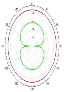
RadiationPattern
Anessential typeof radiofrequency antenna isthe dipole antenna, sometimes known as the dipole aerial. A more complex antenna arraymay include thedipole or it might be used alone. The dipole aerial, commonly known as an antenna, is frequently used both independently and in many different RF antenna designs as the radiating or driving part of the antenna as a whole. The dipole's basic operation is rather simple, and many of the computations involved are also very simple. An HF, VHF, and UHF portion of the radio frequency spectrum may be easily operated by designing a simple dipole antenna. Nevertheless, a more complex mathematical approach may be necessary for a thorough mathematical examination.
Alargenumberofresearchersandacademicshaveshown interest in planar antennas throughout the past few decades. A tiny, compact antenna that can be integrated withMMIC designhasbecome moreand more in demand since the early 1970s revolution in electronic circuit shrinkingandlarge-scaleintegration.Thesubstrate-based antennas known as planar antennas are simple to fabricateandintegratewithMMICsandPCBs.Lowprofile, small weight, and simplicity of construction are some of thebenefitsoftheseantennas.
Table
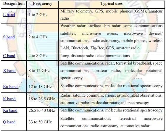
Whenscientistsdiscoveredthatabouthalfofthepowerin a microstrip radiator escapes as radiation, they understood the significance of microstrip radiators. Consequently, a microstrip antenna was described as a microstripemittingpatchwithasignificantradiationloss. Subsequent research demonstrated that the discontinuities at each end of the microstrip transmission line were the source of this radiation process. A patch antenna's fundamental design consists of a flat plate placedoveragroundplaneandadielectricsubstrate.
According to the transmission line concept, the rectangularpatchantenna,asseeninFigisaparallelplate transmission line connecting to radiating slots that are each width W and height h. The charge is dispersed throughoutthegroundplaneandthepatch'sbottomwhen it is stimulated by a feed line. The attractive forces between the ground plane and the patch's bottom tend to storealotofchargeatanygivenmoment.
In wireless communication, an electromagnetic wave is usually radiated into space using a microstrip patch antenna.Amicrostrippatchantennaconsistsoffourbasic parts: feed, patch, substrate, and ground. It has a ground plane on one side and a dielectric constant on the other, and it can be square, elliptical, circular, rectangular, or ring-shaped. Microstrip patch antennas are used in many different applications, such as tracking logistics and automobiles. microwavecommunicationand theglobal
International Research Journal of Engineering and Technology (IRJET) e-ISSN: 2395-0056 p-ISSN: 2395-0072
Volume: 11 Issue: 04 | Apr 2024 www.irjet.net
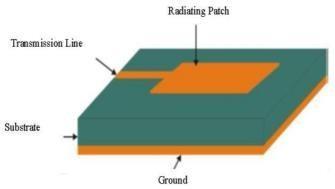
positioningsystem(GPS).Amicrostripantennaisdepicted inFigure,whereWdenoteswidth,Ldenoteslength,andε represents the effective dielectric constant of the rectangular patch. The creation of a patch antenna for wireless communication is covered in this section as it is widely known that these antennas may be installed on printed circuit boards (PCBs) for a variety of communicationdevices.
SampleparagraphDefineabbreviationsandacronymsthe first time they are used in the text, even after they have beendefinedintheabstract.AbbreviationssuchasIEEE,SI, MKS,CGS,sc,dc,andrmsdonothavetobedefined.Donot use abbreviations in the title or heads unless they are unavoidable.
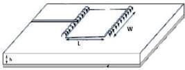
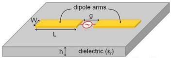
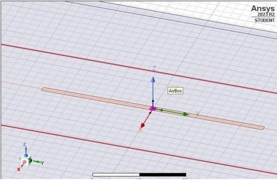
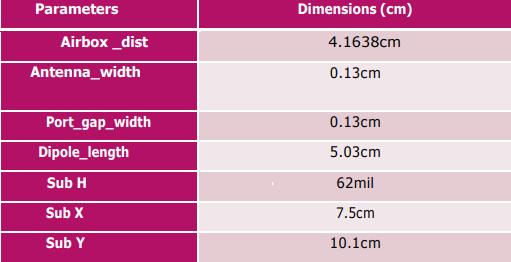
Ansoft Designer is used to create and simulate a printed dipoleantennawithadifferentialfeedinthislesson.When anomnidirectionalpatternisneededforplanarmicrowave radiative applications, the printed dipole antenna is frequentlyutilized.Fig.1displaystheprinteddipolemodel. The feed gap (g) and substrate height (h) will remain stable,and the dipolearm'swidth(W)and length(L)will be tuned for 3.0 GHz operation. There is an outline of the modelandsimulationsetup.
5.2
Volume: 11 Issue: 04 | Apr 2024 www.irjet.net
International Research Journal of Engineering and Technology (IRJET) e-ISSN: 2395-0056 p-ISSN: 2395-0072
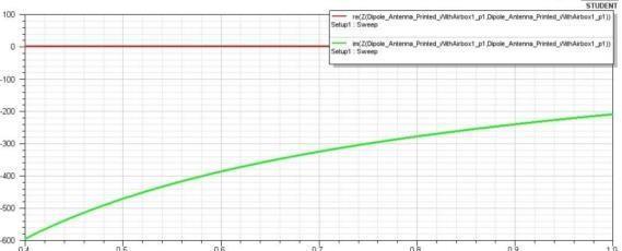
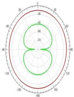
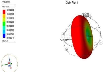
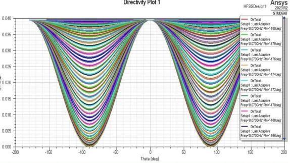
6. RESULTS
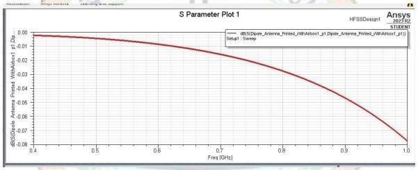
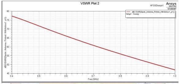
Based on the outcome of the simulation, it was concluded that the parameter was correct. For mobile and wireless technologies,thebasicvalueis -1.04dB,whichisidle.For optimal operation, the antenna is set to the necessary frequency. The S11 parameter characterizes the return loss of the planned antenna, and the frequency of operationis1.1GHz,asshowninthepicturebelow.Return loss'svalueis
International Research Journal of Engineering and Technology (IRJET) e-ISSN: 2395-0056 p-ISSN: 2395-0072
Volume: 11 Issue: 04 | Apr 2024 www.irjet.net
In this work, a printed dipole antenna with a resonance frequency of 0GHz is created, and simulated, and the results of the simulation are recorded at my_mat_ADK as the substrate. A printed dipole antenna has a 1.1GHz bandwidth. Using HFSS software, the printed dipole antennaissimulated.
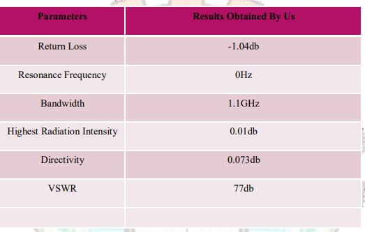
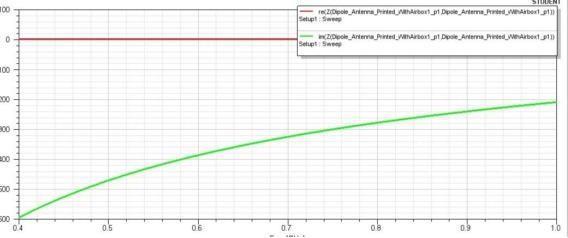
Table-3: Comaparission
[1] R. K. Bajpai, R. Paulus, A. Singh, and M. Aneesh, ‘‘Review: dual-band microstrip antennas for wireless applications,’’ International Journal of Advances in Applied Sciences (IJAAS), vol. 7, no. 2, pp. 143-151, Jun.2018,doi:10.11591/ijaas.v7.i2.pp143-151.
[2] T. S. Rappaport et al., "Millimeter wave mobile communicationsfor5Gcellular:itwillwork!,"inIEEE Access, vol. 1, pp. 335-349, 2013, doi: 10.1109/ACCESS.2013.2260813.
[3] M. Attaran, ‘‘The impact of 5G on the evolution of intelligent automation and industry digitization,’’ Journal of Ambient Intelligence and Humanized Computing,Feb.2021,pp.1-17, doi: 10.1007/s12652020-02521-x.
[4] S.Ershadi,A.Keshtkar,A.H.Abdelrahman,andH.Xin, ‘‘Wideband high gain antenna subarray for 5G applications,’’ Progress in Electromagnetics Research C, vol. 78, pp. 33–46, 2017, doi: 10.2528/pierc17061301.
[5] A. Derneryd, "A theoretical investigation of the rectangular microstrip antenna element," in IEEE Transactions on Antennas and Propagation, vol. 26, no. 4, pp. 532-535, July 1978, doi: 10.1109/TAP.1978.1141890.


MR.CH.Vijaya Shekhar Babu AssistantProfessoratKrishna UniversityCollegeofEngg& Techno,Machilipatnam,APIndia
Ms. Reshma Dasari iscurrentlya studentfromtheDepartmentof ECEatKRUCET.Machilipatnam, APIndia
N.Siva Sagar iscurrentlya studentfromtheDepartmentof ECEatKRUCET.Machilipatnam, APIndia
B. Sandeep iscurrentlyastudent fromtheDepartmentofECEat KRUCET.Machilipatnam,APIndia
C Bhanu Prasad iscurrentlya studentfromtheDepartmentof ECEatKRUCET.Machilipatnam, APIndia.