
International Research Journal of Engineering and Technology (IRJET) e-ISSN: 2395-0056
Volume: 11 Issue: 04 | Apr 2024 www.irjet.net p-ISSN: 2395-0072

International Research Journal of Engineering and Technology (IRJET) e-ISSN: 2395-0056
Volume: 11 Issue: 04 | Apr 2024 www.irjet.net p-ISSN: 2395-0072
Mr. Ch. Vijaya Sekhar Babu1 , Assistant Professor1
R. Sri Lakshmi2 , A. Suraj3 , S. Chandra Mouli4, Y. Susanthi Sheela5, P. Haritha6 ,
UG Students23456
Department of ECE
Krishna University College of Engineering and Technology ***
Abstract -As the user base grows, so does the need for improved technology. By utilizing the vast quantity of spectrum in the millimeter wave band, fifth generation (5G) technology will be among the best at meeting the demands for huge connection, expanded capacity, and faster speeds. It is anticipated that 5G would provide speeds of 80–100 Mbps. The necessity of 5G technology, antenna design approach, and several simulations are shown. Because of its straightforward physical structure, the micro strip patch antenna utilized in 5G technology is relatively affordable to build and design. Due to its tiny design and multi-band capabilities, the Micro Strip Patch Antenna has become a highly promising option for portable devices. The HFSS program, which is used to design antennas, is utilized to put thesuggested notion intopractice.
Key Words:4G, 5G, UHD, IP, GSM
Theroleofmicrostrippatchantennasinmodernwireless communication systems is growing. Antennas come in a variety of forms; folding dipole, patch, slot, and parabolic reflector antennas are just a few examples. Every type of antennahasauniqueuseandauniquesetofproperties.It is possible to argue that antennas form the foundation of almost everything in wireless communication, without whichthemodernworldwouldnothaveprogressedtothis point in technological advancement. These days, radio frequency (RF) and wireless communication technologies are widely used in many industrial applications as well as daily human activities. In recent years, a plethora of wireless communication technologies have emerged, such as wireless broadband, wireless local area network, wireless interoperability for microwave access, and more. Although the microstrip patch antenna has a restricted bandwidth,a disordered radiation pattern,and weak gain, itisanexcellentfitforRFcommunicationsystems.
Well, 5G is superior to 4G for a number of reasons. The quicker upload and download speeds are among the key benefits.5Gismorehandyforoperationslikesharinghuge filesorwatchinghigh-definitionfilmssinceitallowsyouto download and upload data considerably faster. A further benefitisthedecreasedlatency,whichresultsina shorter
transmission delay for data. A quicker reaction time is essential for real-time applications like gaming and video calls, therefore this is especially significant. Furthermore, without compromising performance, 5G has the ability to accommodate more connected devices concurrently. This is excellent news for smart home technology and the expandingnumberofIoTdevices.
Theobjectiveofthisthesisistododesignandsimulationof Printed Antenna Design for 5G Wireless Communications. Antenna with wide band characteristics is designed and simulatedusingcommercialtoolHFSS.
Antennas are designed for the frequency range using designconsiderationsandprocedures.
•ModeltheantennausingHFSS.
•Simulatingandoptimizingdesignparameters
2. Literature review
In the world of wirelesscommunication networks thatwe currently inhabit, patch antennas play a critical role. A microstrip patch antenna is relatively simple to construct and uses a more popular microstrip manufacturing technique.Althoughthereisnolimittohowthepatchmay be formed, the most popular forms are rectangular and circular. The most demanding and widest variety of applications are served by these patch antennas in the most straightforward manner . The technical work of severalstudiesonmicrostrippatchantennasisincludedin this part. This article proposes a broadband rectangular patch antenna that can be utilized for 5G wireless applicationsinthefuture.
The role that patchantennas play in the world of wireless communication networks that we live in is crucial. With S11valuesoflessthan-15dB,theproposedantennafor5G communication achieves a broadband impedance bandwidth of higher than 67 percent (from 39GHz to beyond 44GHz). The achieved bandwidth is enough to cover the 28 and 38 GHz bands of the upcoming 5G network. With the exception of the rejected band, the
International Research Journal of Engineering and Technology (IRJET) e-ISSN: 2395-0056
Volume: 11 Issue: 04 | Apr 2024 www.irjet.net p-ISSN: 2395-0072
proposed antenna has almost omnidirectional patterns, a comparatively flat gain, and high radiation efficiency throughout the frequency range. Several designs for rectangular microstrip antennas are described in this paper .All of these antennas function at 38 GHz, which is oneofthestandardfrequenciesfor5Gcommunications.
Anarrayarrangementusesacorporatefeedingnetworkto provide more precise impedance matching. It improves radiationpattern,gain,impedancebandwidth,returnsloss characteristics,and other performance elements. Gain and directivityaretwofurtherperformanceindicatorsthatare now benefited by this. A microstrip patch antenna is relatively simple to construct and uses a more popular microstrip manufacturing technique. Although there is no limit to how the patch may be formed, the most popular forms are rectangular and circular. The most demanding and widest variety of applications are served by these patch antennas in the most straightforward manner . The technical work of several studies on microstrip patch antennas is included in this part. This article proposes a broadband rectangular patch antenna that can be utilized for5Gwirelessapplicationsinthefuture.
3. An introduction to HFSS
HFSSutilizesthewell-knownMicrosoftWindowsgraphical user interface to provide a high-performance full-wave electromagnetic (EM) field simulator for arbitrary 3D volumetric passive device simulation. It combines solid modeling, automation, simulation, and visualization into a user-friendlyenvironmentthatmakesitsimpletogetfast, accurate answers to your 3D EM challenges. With Ansoft HFSS, you can solve any of your 3D EM issues with unmatched performance and understanding thanks to the Finite Element Method (FEM), adaptive meshing, and stunning visuals. Fields, Resonant Frequency, and SParametersmayallbecomputedusingasoftHFSS.
Package Modeling: BGA,QFP,Flip-Chip, PCB
Board Modeling: Power/Ground planes, Mesh GridGrounds,Backplanes,
Silicon/GaAs: SpiralInductors,Transformers
EMC/EMI:ShieldEnclosures,Coupling,Near-Field orFar-FieldRadiationAntennas/Mobile
Communications: Patches, Dipoles, Horns, ConformalCellPhoneAntennas,QuadrafilarHelix, Specific Absorption Rate(SAR), Infinite Arrays, Radar Cross Section(RCS), Frequency Selective Surfaces(FSS)
Connectors: Coax, SFP/XFP, Backplane, Transitions
Waveguide: Filters,Resonators,Transitions,
Couplers Filters: Cavity Filters, Microstrip Dielectric
Alotofacademicsandresearchershavebeeninterestedin planarantennasduringthepastfewdecades.Theneedfor a tiny, compact antenna that can be combined with MMIC design has grown since the early 1970s large-scale integration and shrinking of electronic circuits. Substratebased planar antennas are simple to manufacture and integrate with MMICs and PCBs. These antennas have benefits including simplicity of construction, light weight, andlowprofile.
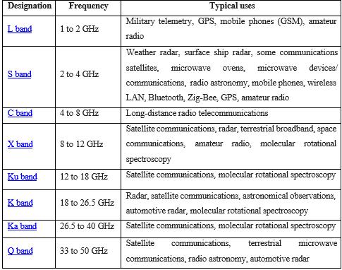
Table -1:frequencyspectrum
Although there are many other types of patch structures, the rectangular, circular, and triangular designs are the most commonly utilized. As planar patch antennas advanced,sodidthedesignofS-band(WIMAX)andC-band (WLAN) antennas.The electromagnetic spectrum's microwave band includes the S-band. It transcends the traditional 3.0 GHz line that separates UHF and SHF frequencies,andisspecifiedbyanIEEEstandardforradio waves with frequencies that extend from 2 to 4 GHz. Surfaceshipradarandweatherradarbothusethe Sband. Someregionsoftheelectromagneticspectrum,particularly microwave frequencies utilized in long-distance communications,arereferredtoastheC-band.TheC-band (4 to 8 GHz) and its slightly modified frequencies are utilized by certain Wi-Fi devices, certain cordless phones, andcertainweatherradarsystems.
Whenscientistsdiscoveredthatabouthalfofthepowerin amicrostripradiatorescapesasradiation,theyunderstood the significance of microstrip radiators. Consequently,
International Research Journal of Engineering and Technology (IRJET) e-ISSN: 2395-0056
Volume: 11 Issue: 04 | Apr 2024 www.irjet.net p-ISSN: 2395-0072
microstrip antennas were characterized as a microstrip emittingpatchwithasignificantradiationloss.Subsequent researchdemonstratedthatthediscontinuitiesateachend ofthemicrostriptransmissionlinewerethesourceofthis radiationprocess.

Fig -1:Thebasicgeometryofmicrostripradiator
Radiating patches may be built in many different ways, including square, circular, triangle, semicircular, sectorial, andannularringforms.However,duetotheirsimplicityin manufacture and analysis, rectangular and circular configurationsarethemostwidelyutilized.
Accordingtothetransmissionlinemodel,asillustratedby Fig the rectangular patch antenna is a parallel plate transmission line that connects to radiating slots that are each of width W and height h. Charge is dispersed throughoutthegroundplaneandthepatch'sbottomwhen it is stimulated by a feed line. The attractive forces betweenthegroundplaneandthepatch'sbottomtend to storealotofchargeatanygivenmoment.Additionally,the charges are pushed to the patch's edge by the repulsive forces,whichresultsinahighchargedensityontheedges.

In wireless communication, an electromagnetic wave is usuallyradiateintospaceusingamicrostrippatchantenna. A microstrip patch antenna consists of four basic parts: feed,patch,substrate,andground.Ithasagroundplaneon one side and a dielectric constant on the other, and it can be square, elliptical, circular, rectangular, or ring-shaped.
Microstrip patch antennas are used in many different applications, such as microwave communication, global positioning system (GPS), logistics tracking, and automotive. A microstrip antenna is depicted in Figure, where W represents width, L represents length, and ε represents the effective dielectric constant of the rectangularpatch.
4.1 Designing of rectangular patch antenna
4.1.1 Determine Design Parameters:
Frequency: Define the operating frequency or frequency range of your antenna. Dielectric Substrate: Choose a suitable dielectric substrate material. FR4 is commonly used. Permittivity (εr): Select the permittivity of the substratematerial.PatchDimensions:Determinethemajor andminoraxesoftherectangularpatch
4.1.2 Calculate Patch Dimensions:


Table-2:Dimensionsoftheantenna
5. Design of rectangular patch antenna in HFSS
Step 1: creatingagroundplaneMaterial:copper
Positions: 0,0,0 X size: length of the substrate Y size: width of the substrate Z size: height of the patch
International Research Journal of Engineering and Technology (IRJET) e-ISSN: 2395-0056
Volume: 11 Issue: 04 | Apr 2024 www.irjet.net p-ISSN: 2395-0072
Step 2: creating a substrate Material: FR4-epoxy Positions :0,0,0.035 X size: length of the substrate Y size; width of the substrate Z size: height of the substrate
Step 3: creating a patch Material: copper Positions: A,Ws/2-Wp/2,Hp+Hs X size: length of thepatchYsize:widthofthepatchZsize:heightof thepatch
Step 4: insetfeed
Material: copper Position: A+Lp, Ws/2Wf/2,Hp+Hs X size: Ls-A-Lp Y size: width of the feedZsize:heightofthepatch
Step 5: giving excitation Position: Ls,Ws/2Wf/2,(Hp+Hs) Y size: width of the feed Z size:(Hp+Hs)
Step6:creating radiation boundary Operatingfrequency:15GHz


Returnloss:Theparameterwasdeterminedtobeaccurate based on the simulation final results. The base value is6dB,whichis idleformobileandwirelesstechnology.The antenna is tuned to the required frequency to function properly. As can be seen in the below figure, it runs at a frequencyof42.15GHz,S11parameterdescribesthereturn loss of the designed antenna. the value of return loss is30.54dB which is very high ensuring perfectcandidate for 5Gapplications.

International Research Journal of Engineering and Technology (IRJET) e-ISSN: 2395-0056
Volume: 11 Issue: 04 | Apr 2024 www.irjet.net p-ISSN: 2395-0072

Fig -9:VSWR

Fig -10:Radiationpattern
The radiation pattern of an antenna refers to the directionaldistributionofitselectromagneticenergyinthe space.plotorgraphshowingtheantenna’ssignal strength asafunctionofangle.

Fig -11:Impedance

Fig -12:Diectivity
Inthisstudy,amicrostrippatchantennawitharesonance frequency of 42.15GHz is constructed, simulated, and the resultsofthesimulationarerecordedusingFR-4epoxyas the substrate. To create an antenna, one uses the inset feeding approach. Rectangular patch antennas have a 4.5GHzbandwidth.the computer programwith the use of a rectangularpatchantennaandHFSSsoftware.

Table-2:Results
[1] D. Kornack and P. Rakic, “Cell Proliferation without Neurogenesis in Adult Primate Neocortex,” Science, vol. 294, Dec. 2001, pp. 2127-2130, doi:10.1126/science.1065467.
[2] M. Young, The Technical Writer’s Handbook. Mill Valley,CA:UniversityScience,1989.
[3] R. Nicole, “Title of paper with only first word capitalized,”J.NameStand.Abbrev.,inpress.
[4] K.Elissa,“Titleofpaperifknown,”unpublished.


Mr. Ch. Vijaya Sekhar Babu AssistantProfessorat Krishna University CollegeofEngg& Techno,Machilipatnam,APIndia

2nd 1’st

Ms. R. Sri Lakshmi iscurrently student from Department of ECE fromKRUCET,Machilipatnam,AP India
International Research Journal of Engineering and Technology (IRJET) e-ISSN: 2395-0056
Volume: 11 Issue: 04 | Apr 2024 www.irjet.net p-ISSN: 2395-0072

Mr. A.Suraj iscurrently student from Department of ECE from KRUCET,Machilipatnam,APIndia

Mr. S. Chandra Mouli iscurrently student from Department of ECE fromKRUCET,Machilipatnam,AP India

Ms.Y. Susanthi Sheela is currently Student from Department of ECE From KRUCET,Machilipatnam,APIndia

Ms. P. Haritha is currently student from Department of ECE fromKRUCET,Machilipatnam,AP India