
International Research Journal of Engineering and Technology (IRJET) e-ISSN: 2395-0056
Volume: 11 Issue: 04 | Apr 2024 www.irjet.net p-ISSN: 2395-0072
International Research Journal of Engineering and Technology (IRJET) e-ISSN: 2395-0056
Volume: 11 Issue: 04 | Apr 2024 www.irjet.net p-ISSN: 2395-0072
Mr. Ch. Vijaya Sekhar Babu1 , Assistant Professor1 Y. Susanthi Sheela2 , P. Haritha3, K. Santha Kumari4, S. Chandra Mouli5, D. Reshma6 ,
UG Students23456 Department of ECE Krishna University College of Engineering and Technology, ***
Abstract -ThedesignandperformanceassessmentofanEshaped microstrip patch antenna with edge feeding and Defected GroundStructure (DGS) at aresonant frequency of 5.2 GHz are presented in this work. The antenna shows a stunning return loss of -30.6038 dB and an impressive gain of 5.58, indicating effective impedance matching and radiation characteristics. Edge feeding and DGS improve directivity and reduce undesired radiation, which improves antenna performance. For a variety of wireless communication applications requiring excellent performance in the 5.2 GHz frequency region, this small and effectiveantennadesignshowspromise.
Key Words: ANSYS HFSS, E-shaped, Edge Feed, FR4 epoxy, S-parameter, Gain, Directivity, VSWR.
1.INTRODUCTION
The need for high-performance, small-sized antennas that operate at certain frequencies is constantly growing in today's wireless communication systems.Microstrip patch antennas are unique among antenna designs because of their small size, light weight, and simplicity of integration intoelectricalsystems.Inordertoobtainagainof5.58and areturnlossof-30.6038dB,thisbriefdescribesthedesign ofanE-shapedmicrostrippatchantennawithedgefeeding andDefectedGroundStructure(DGS)operatingat5.2GHz. Unique benefits of the E-shaped microstrip patch antenna arrangement include better impedance matching and increased tuning possibilities. This design modification improves control over the antenna's resonance frequency and radiation properties by adding a letter "E"-shaped protrusion to the rectangular patch. To reduce complexity andboostantennaperformance,edgefeeding placingthe feeding mechanism along the patch's edge is used. This feeding method keeps the antenna footprint small while enablingeffectivestimulationoftheradiatingcomponents.
1.1 Statement of the problem
The task at hand involves creating a microstrip patch antennathatcanoperateat5.2GHzandhastwospecified parameters:areturnlossof-30.6038dBandagainof5.58. An E-shaped patch with edge feeding on a Defected
Ground Structure (DGS) is part of the antenna layout. Optimizing the antenna's size and feed structure to meet the required performance standards within the available frequencyrangeisthedifficultpart.
1.2 Objective
With a phenomenal return loss of -30.6038 dB and an operating frequency of 5.2 GHz, an E-shaped microstrip patch antenna edge-fed with defective ground structure (DGS) performs very well in small wireless communicationsystems.
1.3 Methodology
Designconsiderationsandprocessesareusedtocreatean antennatailoredtothedesiredfrequencyrange.
•UseHFSStomodeltheantenna.
•Designparameteroptimizationandsimulation.
2. Literature review
Due to its promising performance features, the E-shaped microstrip patch antenna with edge feeding on Defected Ground Structure(DGS)operatingat5.2 GHzhas received a lot of attention in recent research. When compared to traditional patch antennas, the E-shaped arrangement has a numberofbenefits,suchassmallsize,broadbandwidth, and improved radiation properties. The antenna's performance is further enhanced by the addition of Defective Ground Structure, which lowers radiation losses and suppresses surface wave excitation, improving gain andbandwidth.Severalresearchconcentratingondifferent facets of this antenna design have been published, according to a thorough study of the literature. To maximize performance metrics including gain, return loss, bandwidth,andradiationpattern,researchershavelooked at various materials, substrate designs, and feeding methods. To assess and improve the antenna's performance, a number of design approaches have been used, including experimental validation and numerical simulations with electromagnetic simulation software. To comprehend how feeding methods, substrate characteristics, and geometrical aspects affect antenna
Volume: 11 Issue: 04 | Apr 2024 www.irjet.net p-ISSN: 2395-0072
performance, parametric studies have been carried out.Additionally, attempts have been made to improve the antenna's performance for certain uses, such satellite communications, radar systems, and wireless communicationsystems.Methodslikeasfrequencytuning, polarizationdiversity,andmetmaterial loadinghavebeen investigated to customize the antenna properties to fit variousapplications
The literature, taken as a whole, highlights the potential uses of the E-shaped microstrip patch antenna with edge feeding on DGS at 5.2 GHz for a variety of wireless communication and sensing applications. To increase this antenna configuration's performance and adaptability, more investigation is necessary into novel design ideas, manufacturingprocesses,andintegrationopportunities.
High-performance full-wave electromagnetic (EM) field simulator HFSS leverages the graphical user interface of Microsoft Windows to enable arbitrary 3D volumetric passive device modeling. Solutions to your 3D EM challenges may be acquired fast and precisely because to its integration of solid modeling, automation, simulation, and visualization in an intuitive learning environment. To provideyouwithunmatchedperformanceandinsightinto all of your 3D EM challenges, Ansoft HFSS uses adaptive meshing, the Finite Element Method (FEM), and stunning visualizations. Measurements like S-parameters, resonant frequency,andfieldsmaybecomputedusingansoftHFSS.
Planar antennas have drawn the attention of several academics and researchers throughout the past few decades.Theneedforasmall,compactantennathatcanbe combined with MMIC design has grown since the early 1970s, when electronic circuit downsizing and large-scale integration underwent a revolution. Substrate-based planar antennas are simple to manufacture and integrate with MMICs and PCBs. These antennas have benefits including simplicity of construction, light weight, and low profile.
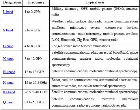
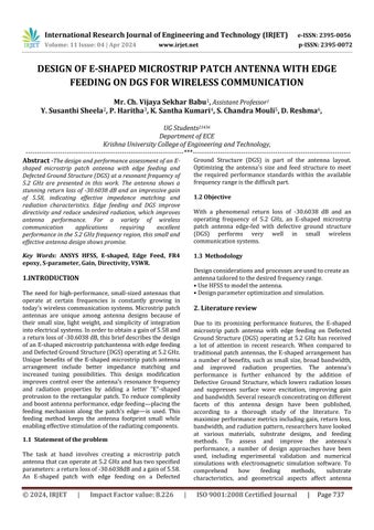
Table -1: frequencyspectrum
The electromagnetic spectrum's microwave band includes the S-band. It transcends the traditional 3.0 GHz line that separatesUHF andSHF frequencies,andisspecifiedbyan IEEE standard for radio waves with frequencies that extend from 2 to 4 GHz. Radar used by surface ships and weather stations both operate in the S band. Certain regions of the electromagnetic spectrum, such as microwave wavelengths utilized for long-distance communications,arereferredtoastheC-band.TheC-band (4to8GHz)anditssomewhatmodifiedbandsencompass frequency ranges utilizedbycertain Wi-Figadgets,certain cordlessphones,andcertainweatherradarsystems.
Whenscientistsdiscoveredthatabouthalfofthepowerin amicrostripradiatorescapesasradiation,theyunderstood the significance of microstrip radiators. Consequently, microstrip antennas were characterized as a microstrip emittingpatchwithasignificantradiationloss.Subsequent researchdemonstratedthatthediscontinuitiesateachend ofthemicrostriptransmissionlinewerethesourceofthis radiation process. A patch antenna's fundamental design consists of a flat plate placed over a ground plane and a dielectric substrate. Copper foil is often used to make the metal patch, however other forms of substrate material maybeusedinstead,dependingonthesituation.Asseenin Fig., the three layers are the bare minimum required to describeapatchantenna.
-1:Thefundamental
International Research Journal of Engineering and Technology (IRJET) e-ISSN: 2395-0056
Volume: 11 Issue: 04 | Apr 2024 www.irjet.net
The majority of the analytical techniques for patch antennas take into account the 2D planar element. The transmissionlinemodel,cavitymodel,andfullwavemodel are the three most used analytical techniques. The most basicmodelisthetransmissionlinemodel,whichprovides a decent physical understanding but is not particularly precise. Although it is more difficult, the cavity model provideshighaccuracyandphysicalunderstanding.Lastly, compared to the other two models, the complete wave model is significantly more complicated to use and by far themostaccurateandadaptablemodel.Italsooffersmore alternatives.However,itprovideslessphysicalknowledge.
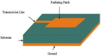
Accordingtothetransmissionlineconcept,therectangular patch antenna, as seen in Figis a parallel plate transmission line connecting to radiating slots that are each of width W and height h. Charge is dispersed throughoutthegroundplaneandthepatch'sbottomwhen itisstimulatedbyafeedline.Theattractiveforcesbetween thegroundplaneandthepatch'sbottomtendtostorealot of charge at any given moment. Additionally, the charges are pushed to the patch's edge by the repulsive forces, whichresultsinahighchargedensityontheedges.
In wireless communication, a microstrip patch antenna is most frequently used to emit electromagnetic waves into space.Amicrostrippatchantenna'sfourbasicpartsarethe ground,substrate,patch,andfeed.Ithasagroundplaneon one side and a dielectric constant on the other, and it can be square, elliptical, circular, rectangular, or ring-shaped. Microstrippatch antennas are used in many different applications, including as microwave communication, globalpositioningsystems(GPS),automotive,andlogistics tracking.AmicrostripantennaisdepictedinFigure1with W representing thewidth,L thelength,andεthe effective dielectricconstantoftherectangularpatch
5.2 Designing of E-Shaped patch antenna
To maximize its performance, an E-shaped patch antenna must be designed using a number of procedures and considerations. The main principles for creating an EShapedpatchantennaarelistedbelow:
p-ISSN: 2395-0072
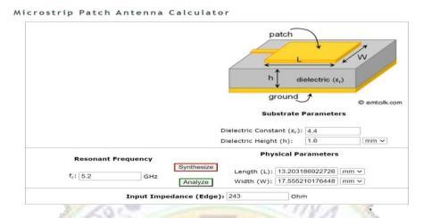
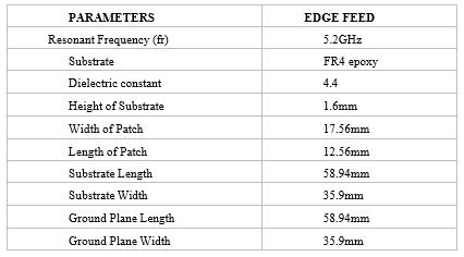
1. Establishthefrequencyrangeoroperational frequencyofyourantenna.
2. Selectinganappropriatedielectricsubstrate materialisimportant.It'scustomarytoutilizeFR4.
3. Determinethepermittivity(εr)ofthesubstrate material
4. PatchDimensions:FindtheE-Shapedpatch's majorandminoraxes.
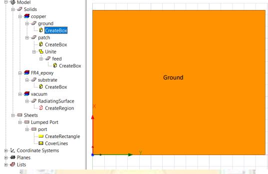
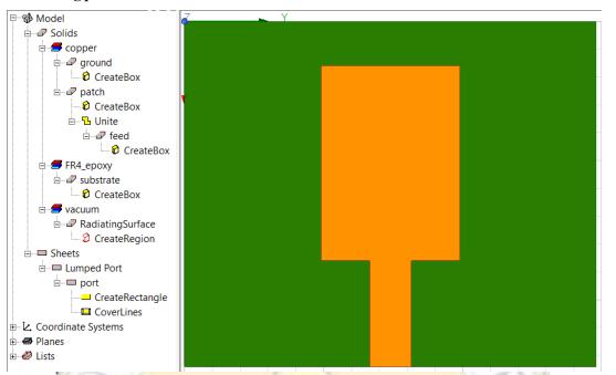
6. Design of rectangular patch antenna in HFSS
Step 1: creating a ground plane Material: copper Positions: 0,0,0 X size: length of the substrate Y size: width of the substrate Z size: height of the patch
Step 2: creating a substrate Material: FR4-epoxy Positions :0,0,1.6 X size: length of the substrate Y size; width of the substrate Z size: height of the substrate
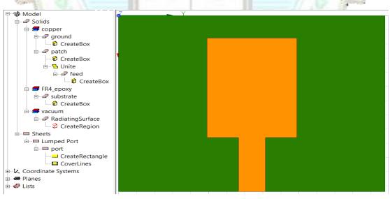
Step 3: creating a patch Material: copper Positions:A,Ws/2-Wp/2,Hp+Hs
Step 4: Edgefeed
Material: copper Position: A+Lp, Ws/2Wf/2,Hp+Hs X size: Ls-A-Lp Y size: width of the feedZsize:heightofthepatch
International Research Journal of Engineering and Technology (IRJET)
Volume: 11 Issue: 04 | Apr 2024 www.irjet.net
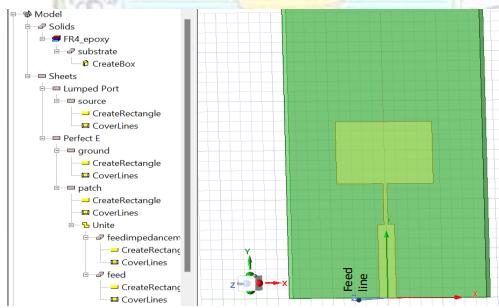
Step5: giving excitation Position: Ls,Ws/2Wf/2,(Hp+Hs) Y size: width of the feed Z size:(Hp+Hs)
Step6:creating radiation boundary Operatingfrequency:5.2GHz
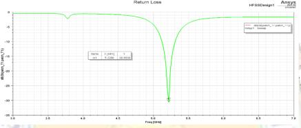
Asystem'sorantenna'sabilitytoreflectpowerbacktothe source is measured by its return loss. It resembles the quantity of signal that is reflected back rather than sent forward. The aforementioned result suggests that the antenna exhibits perfect radiation since the return loss is relativelysmallattheradiatedfrequencyof5.2GHz.
International Research Journal of Engineering and Technology (IRJET) e-ISSN: 2395-0056
Volume: 11 Issue: 04 | Apr 2024 www.irjet.net p-ISSN: 2395-0072
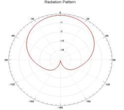
Fig -10:Radiationpattern
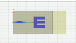
Fig -11:E-plane
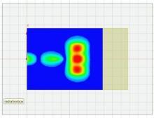
Fig -12:H-plane
8. CONCLUSIONS
Inthisstudy,amicrostrippatchantennawitharesonance frequency of 5.2 GHz is constructed, simulated, and the resultsofthesimulationarerecordedusingFR-4epoxyas the substrate. The antenna design process uses the inset feeding approach. The E-Shaped patch antenna has a 5.2GHz bandwidth. Using HFSS software, an E-shaped patchantennaissimulated.
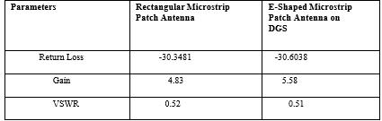
Table-2: Results
[1] P-Y. Qin, Y. J. Guo, and C. H. Liang, “Effect of antenna polarizationdiversityonMIMOsystemcapacity,”IEEE Antennaswirelesspropag.Lett.,vol.9,pp.1092–1095, 2010.M.Young,TheTechnicalWriter’sHandbook.Mill Valley,CA:UniversityScience,1989.
[2] Yong-XinGuo;Kah-WeeKhoo;LingChuenOng"Wide band Circularly Polarized Patch Antenna Using Broadband Baluns" Antennas and Propagation, IEEE TransactionsonVolume56,Issue2,Feb.2008.
[3] J-H. Lu, and S-F. Wang “Planar broadband circularly polarized antenna with square slot for UHF RFIDreader,”IEEETrans.AntennasPropag,vol.61,no. 1,pp.45-53,Jan.2013.
[4] B. Ooi, S. Qin and M. Leong, "Novel design of broadband stacked patch antenna," IEEE Transactionson Antennas and Propagation, vol. 50, no.10, pp. 13911395, Oct.2002.


Mr. Ch. Vijaya Sekhar Babu AssistantProfessorat Krishna University College of Engg& Techno,Machilipatnam,APIndia

Ms. Y. Susanthi Sheela is currently Student from Department of ECE From KRUCET, Machilipatnam,APIndia


Ms. P. Haritha is currently student from Department of ECE from KRUCET, Machilipatnam, AP India
International Research Journal of Engineering and Technology (IRJET) e-ISSN: 2395-0056
Volume: 11 Issue: 04 | Apr 2024 www.irjet.net p-ISSN: 2395-0072

Author
Ms. K. Santha Kumari iscurrently student from Department of ECE from KRUCET, Machilipatnam, AP India

Author
Mr. S. Chandra Mouli is currently student from Department of ECE from KRUCET, Machilipatnam, AP India


Author
Ms. D. Reshma is currently student from Department of ECE from KRUCET, Machilipatnam, AP India