
International Research Journal of Engineering and Technology (IRJET) e-ISSN: 2395-0056
Volume: 11 Issue: 04 | Apr 2024 www.irjet.net p-ISSN: 2395-0072
International Research Journal of Engineering and Technology (IRJET) e-ISSN: 2395-0056
Volume: 11 Issue: 04 | Apr 2024 www.irjet.net p-ISSN: 2395-0072
Tusharkant Panda1 , Tejaswini Behera2, Swati Saswati Biswal2, Swati Swagatika Nanda2 , Apurba Kumar Swain2
1Assistant Professor, ECE department, GIETU, Gunupur, Odisha, India
2UG Scholar, ECE department, GIETU, Gunupur, Odisha, India
Abstract-This paper outlines the design and implementation of a temperature indicator using LM35 temperature sensor and LED without the use of Arduino. The LM35 sensor provides an accurate temperature reading, and the LED visually represents the temperature level. This paper covers the paper’s objectives, components, circuit design, and working principle. The paper provides a captivating blend of temperature monitoring, creating an engaging and informative visual display of changing environmental conditions. This innovative circuit employs a thermistor (LM35), to capture real time temperature data. The sensor’s output is then meticulouslyprocessedbyanintegratedcircuit (IC) that intricately controls a series of vibrant LEDs. What makes this paper truly enticing is its ability to transform mundane data into a mesmerizing visual spectacle. As temperatures rise or fall, the LEDs gracefully light up or dim, creatinga dynamicandeye-catchingdisplay. It canbeusedas a learning tool, or simplya decorativetemperature indicator. The “Temperature indicator LED circuit” paper serves as an excellent example of data visualization in a way that is both accessible and visually captivating.
KeyWords:Temperature;LM35;Measurement;Resistor; IC; LED.
The"Thermoglow:TemperatureGuagewithLM358"paper presents a novel and user-centric solution for real-time temperature monitoring [1,2]. The LM35 temperature sensor has gained popularity for its accuracy and ease of integration.Thispaperpresentsadetailedexplorationofa temperatureindicatorusingtheLM35eliminatingtheneed ofArduinoormicrocontroller[3,4].
The scope of this is wide ranging, with potential applications in diverse fields, offering versatility and adaptabilityforvarioustemperaturemonitoringneeds.Inthis increasinglyinterconnectedandtechnology-drivenworld,we oftenneedtokeepaneyeontemperature,whetherit’sforour comfort at home, in a factory, or even for our health, but understanding temperature can be risky sometimes. The abilitytointerpretandvisualizethisdatainacomprehensible and instinctive manner is essential for making informed decisionsandensuingsafetyandcomfort.LEDsarerenowned ontheirenergyefficiency,brightnessandversatility,making them an ideal choice for creating a visual representation of
temperature information. Thermoglow is an innovative temperatureindicatorleveragingLEDtechnologytoprovidea visual representation of temperature changes [5,6,7]. This intelligent device offers a user-friendly way to monitor temperature variations in various settings. By employing a range of LED colours and patterns, ThermoGlow offers an intuitive and convenient method for users to assess temperature changes, making it an ideal tool for diverse applications, from home use to industrial settings. Its sleek design and functionality make it a versatile and reliable temperatureindicator,cateringtotheneedsofusersacross different environments The LM35 is a precision integratedcircuit temperature sensor that provides an accurate and linearoutputdirectlyproportionaltotheCelsiustemperature. It'sapopularchoicefortemperaturemeasurementduetoits simplicity,accuracy,andeaseofuse.TheLM35sensordoesn't require external calibration or trimming and provides temperature readings in the range of -55°C to 150°C. Its straightforward analogue output makes it compatible with most microcontrollers and digital systems, making it widely utilizedinvariousapplicationssuchasenvironmentalcontrol systems, industrial automation, medical devices, and automotive applications. Its small form factor, low power consumption,andreliabilityhavemadetheLM35astaplein temperaturesensingtechnology[8,9,10].Thesignificanceof LEDTemperatureindicatorliesinitsabilitytoaddressvarious practicalneedsandapplicationssuchas:
i. EnhancedTemperatureMonitoring
ii. EnergyEfficiency
iii. SafetyandComfort
iv. AutomationandControl
v. EducationalTool
vi. ResearchandDevelopment
vii. Versatility
In February 2017, Shekhar Mishra et al in their paper “Temperature Control Based LED indication system” have doneanIndustrialTemperatureControllerusingLED,LM35 Temperature Indicator, and ATS952 Microcontroller [11]. They have also used a 89S52 microcontroller brain, temperature sensor LM35 which senses the actual temperature of the system, to convert the temperature recordedbythesensorintoadigitalquantity,LCDfordisplay andtoturntheLED’sonoroff.In2017,FahimehDehkhoda
International Research Journal of Engineering and Technology (IRJET) e-ISSN: 2395-0056
Volume: 11 Issue: 04 | Apr 2024 www.irjet.net p-ISSN: 2395-0072
etalintheirpaper“LED-BasedTemperatureSensor”have doneaLEDasmicrophotonicemitterusingCMOStechnology [12].Theirpaperrepresentsamethodtomeasurethedevice surface temperature. In 2020, Kyi Kyi Khaing et al in their paper “Automatic Temperature Control System using Arduino”havedoneasimplemethodofTemperaturecontrol system automatically utilising Arduino [13]. Their work is focused mainly on temperature control, and no other parameter is involved. In 2009, A.Goswami et al in their paper “Design of an Embedded System for Monitoring and ControllingTemperatureandLight”havedoneadesignforan embeddedsystemformonitoringthetemperatureandlight intensity [14].Theirpaperdescribes the controlling action incorporatedinthehardware.Inourpaper,wehavedonea TemperatureindicatorusingLEDandLM35withoutthehelp ofArduino.
Afewessentialpartsandproceduresarerequiredwhile designingandmodellinganLM35temperatureindicator usingLEDcircuit.Hereisasimplesimulationandcircuit design.
1) Temperature Sensor (LM35): It is utilized to measuretemperature[15].Theoutputvoltageislinear anddirectlyproportionatetothetemperaturebeing monitored.OneLM35isutilizedhere[16].
2)Operational Amplifier (LM358): It is dual operationalamplifierintegratedcircuit.Itcontainsto separate op-amplifiers with a single 8-pin package. Here1LM358isused.
3) Potentiometer: Itisthetypeofarableresistorthat is often used to adjust resistance. It has three terminals and a movable wiper that makes contact witharesistivetrack.Here1Potentiometerisused. (10kΩ).
4) (Bipolar Junction Transistor BC547): It is used for amplificationandswitchingpurposes[17].ItisNPNtype BJT.Here2BC547sareused.
5) Resistor:Itisdesignedtolimittheflowofcurrentinan electrical circuit. It is measured in ohms (Ω). Here 6 resistorsareused(10kΩ=2,10kΩ=1,1kΩ=1,230Ω=2).
6) LED: - ItisLightEmittingDiode[18].Here2different colouredLEDsareused.Yellow=1,Red=1.
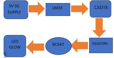
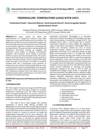
Fig 1: block diagram of circuit LM35
HereWehavetogivethe5vpowersupplytotheLM35’s VCCpin,whichistheinputpinno.1.Thenthepinno2we have to connection with the pin 2(inverting pin) of the LM358 amplifier. The third pin (non-inverting) of the LM358amplifiershouldbeconnectedwiththeground.The non-invertingsideoftheamplifiershouldbeconnectedto 10 KΩ potentiometer. The eighth no. pin of the amplifier shouldbeconnectedtothe5vDCsupply.Thefourthpinof theamplifiershouldbeconnectedtothegroundother5,6,7 pinsofamplifiershouldn’tbeconnectedtoanycomponent The10kΩresistorandpoint2shouldbeconnectedtothe amplifier's1nopinThe10kΩresistorandpoint2shouldbe connectedtotheamplifier's1nopin.Thevariableresistor of10kΩshouldbeconnectedtotheamplifier'ssecondpin. Another10kΩresistorshouldbeconnectedtothevariable resistorwithseriesThetwoLEDshouldbeconnectedwith the2230Ωresistor.
Theconnectionisdoneasperthediagramgiven.

Fig 2: simulation diagram done by using the proteus software.
Thusthispaperoperateswithease.Itreliesona9Vor12V battery to power the circuit, with an IC regulating a 5V supply.Whenthetemperatureisunder50degreesCelsius, the YELLOW LED illuminates while the RED one stays
International Research Journal of Engineering and Technology (IRJET) e-ISSN: 2395-0056
Volume: 11 Issue: 04 | Apr 2024 www.irjet.net p-ISSN: 2395-0072
inactive.ThisisachievedbytheLM35sensoroutputtinga lowsignal,keepingtransistorQ1offandallowingtransistor Q2tostayon.
WhentheLM35outputexceeds0.5volts,itlinkstoPin3of the Op-amp LM358[17]. By establishing the reference voltageat0.5voltsonPin2ofLM35,thevoltageatPin3 (the non-inverting input) surpasses that at Pin 2 (the inverting input). Consequently, the output of the LM35 operational amplifier (PIN 1) rises to a high state. The equations governing the operational amplifier output (Vout)areasfollows:
a) Vout= (R2/R1+R2) * Vin
(Here R2 is the second part of the potentiometer:2kΩ First part of the potentiometer is 10+8=18kΩ)
b) Vout= (2/18+2) * 5=0.5v
3. SIMULATION PARAMETERS

Output of LM35 connected to the base of NPN transistorQ1,soQ1alsobecomesONandRedLEDstart to glow. At the same time, base of Transistor Q2 gets ground and Q2 becomes OFF and Green LED also becomesOFF.Sothisistheprocesshowthecircuitdetects thetemperatureandindicatesbyglowingtheRedLED, whichisthecolourofdanger

Table 1: simulation parameters table
Here the 5v DC supply is given by the DC charger which is initially made by using a stepdown transformer and bridge rectifier to remove the negative lobe of the sinusoidal waveformandaresistorof680Ω.
4. RESULT ANALYSIS
Here in this paper Without the LM358 component in the simulation, the output behaviour changes. When the temperatureremainsbelow50°C,theLM358remainsinactive, keeping Q1 off. Consequently, Q2's base receives power through R2, leading to the illumination of the green LED. However,oncethe temperaturesurpasses50°C,theLM358 generatesanoutput,causingQ1toactivateandtheredLEDto lightup.ThisactionresultsinQ2beingunabletoreceivebias, causing it to turn off. Hence, the paper operates with a thresholdtemperatureof50°C,signifiedbythesechangesin LEDstatus.
5.DESIGN AND IMPLEMENTATION
International Research Journal of Engineering and Technology (IRJET) e-ISSN: 2395-0056
Volume: 11 Issue: 04 | Apr 2024 www.irjet.net p-ISSN: 2395-0072
Hereintheaboveobservationthenaturaltemperatureis below50oC,sothegreenLEDisglowingitself.Greenisthe signofgoodtogosothecircuitwillgiveasignofsafetyfor anyequipmentwhereitwillbeimplemented.
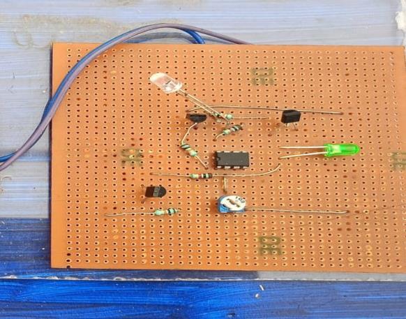
Hereintheaboveanalysisthetemperatureincreasedupto 50oC,sotheredLEDstartedtoglowitself.Anditwillbesign ofdangerforanyequipmentwhereitwillbeimplemented.
6.CONCLUSION
ThepaperinvolvingtheLM35temperatureindicatorusing LED has demonstrated the practical application of temperature sensing and display technology. Through careful design and implementation, we have successfully created a cost effective and efficient temperature monitoring system that can find applications in various fields. This paper underscores the importance of temperature control and measurement in numerous industries,andtheLM35sensor,incombinationwithLED indicators, provides a reliable solution for real-time temperature monitoring. As we move forward, further enhancement and refinements can be made to extend its usability and accuracy, making it an invaluable tool in temperaturemanagementandcontrolsystems.Thispaper not only fulfils its intended purpose but also serves as a testamenttothepotentialforinnovationinelectronicsand sensortechnology.
7.REFERENCE
[1] Goswami,A.,T.Bezboruah,andK.C.Sarma."Design ofanembeddedsystemformonitoringandcontrolling temperature and light." International Journal of ElectronicEngineeringResearch1,no.1(2009):27-36.
[2] Javadpour, Amir, Hamidreza Memarzadeh-Tehran, andFatemehSaghafi."Atemperaturemonitoringsystem incorporating an array of precision wireless thermometers." In Smart Sensors and Application
(ICSSA),2015InternationalConferenceon,pp.155-160. IEEE,2015.
[3] SobotaJ.RaspberryPiandArduinoboardsincontrol educationIFACProc.Vol(2013)
[4] Bubbi J.B., Buyya R., Marusic S., Palaiswami M. InternetofThings(IoT):AVision,ArchitecturalElements, andFutureDirections.FutureGener.Comput.Syst.2013. GadH.E.
[5] Developmentofanewtemperaturedataacquisition system for solar energy applications (2015) Renew. Energy
[6] B. LEVĂRDĂ and C. BUDACIU, "The design of temperaturecontrolsystemusingPic18f4620,"Bulletin ofthePolytechnicInstituteofJassy,Romania,DINIASI,v
[7] Rerkratn,Apinai,andAnuchaKaewpoonsuk."ZigBee based wireless temperature monitoring system for shrimp farm." In Control, Automation and Systems (ICCAS),201515thInternationalConferenceIEEE,2015.
[8] Saidu, G., M. Momoh, and A. S. Mindaudu. "Temperaturemonitoringandloggingsystemsuitablefor use in hospitals incorporating GSM text messaging." International Journal of Information Sciences and Techniques(IJIST)3,no.1(2013
[9] B Baker. High temperature oxygen sensing using K2Mo6CI14LuminescencePoZhangatal.-IEEESensors, 2005
[10] On Temperature soft sensor model of rotary kiln burningzonebasedonRS-LSSVM,Wang&Chen-2017 36thChinesecontrolconference(ccc)-201728
[11] ShekharMishra.TemperaturecontrolbasedLED indicationsystem.InternationalJournalofInnovative Research in Technology. February 2017. Volume 3 Issue9.
[12] Fahimeh Dehkhoda. LED-Based Temperature Sensor.2017IEEE.
[13] KyiKyi Khaing.AutomaticTemperatureControl systemusingArduino.2018(CCC).
[14] Goswami. Design of an Embedded System for Monitoring and Controlling Temperature and Light. International Journal of Electronic Engineering Research.Volume34Number68.
[15] PemanfaatanSensorFotodiodaBerbasisPenguat IC LM358 Sebagai Pendeteksi Jarak Api Pada Saat Kebakaran Simatupang et al. - Jurnal Serambi Engineering-2023.
International Research Journal of Engineering and Technology (IRJET) e-ISSN: 2395-0056
Volume: 11 Issue: 04 | Apr 2024 www.irjet.net p-ISSN: 2395-0072 © 2024, IRJET | Impact Factor value: 8.226 | ISO 9001:2008
[16] digital trace reading potentiometer Bengi & Thomas-JournalofScientificInstruments-1967
[17] IOTbasedsmartrainsensingtechnologyJournal of Institution of Engineers (India): Series B Volume 51/2012-Volume104/2023
[18] IanAshdown.AccurateModelingofLEDColors:A ScientificApproach.Volume-42/1998