
International Research Journal of Engineering and Technology (IRJET) e-ISSN: 2395-0056
Volume: 11 Issue: 04 | Apr 2024 www.irjet.net p-ISSN: 2395-0072
International Research Journal of Engineering and Technology (IRJET) e-ISSN: 2395-0056
Volume: 11 Issue: 04 | Apr 2024 www.irjet.net p-ISSN: 2395-0072
R.
Dharanidaran1 , S. Jagan2 , B. Anandhakeerthi3 , S. Kaveyen4 , U. Gowtham5
2Assistant Professor, Department of Mechatronics, Sri Manakula Vinayagar Engineering College, Puducherry, India 1,3,4,5U.G.Student, Department of Mechatronics, Sri Manakula Vinayagar Engineering College, Puducherry, India
Abstract - The objective of this initiative is to tackle the widespread problem of railway accidents in India, which frequently lead to fatalities as a result of faults in railway tracks, especially fractures. The suggested remedy is using GPS systems in conjunction with sensor technology to pinpoint the exact position of railway track cracks. The Node MCU IoT module is used by the system to gather data from the sensors and send it to the cloud for processing and archiving. At89s52 microcontroller is utilized to supervise the system's overall operation, guaranteeing the smooth integration and synchronization of diverse components. Through real-time crack detection and cloud-based transmission of this information, railway authorities can quickly implement preventive actions like temporary closures or track maintenance to reduce the likelihoodofaccidents.
Key Words: At89s52 microcontroller, IR Sensor, Node MCU,IOTCloud, GPSModule
Certainly,the railwaysystemin India,whilebeingone of themostaffordableandefficientmodesoftransportation, does face significant challenges, particularly regarding safety. The occurrence of accidents resulting in loss of livesandinjuriesunderscorestheneedformodernization and enhanced safety measures within the railway infrastructure.
To address these issues, our model proposes the development of a modernized and secure transportation system. This system would incorporate advanced technologies and methodologies to ensure the safety of passengers and prevent accidents. One crucial aspect is the implementation of predictive maintenance systems that can detect potential issues such as track cracks caused by natural changes in physical and chemical properties. By utilizing sensors and monitoring systems, our model aims to continuously assess the condition of railway tracks and identify early signs of wear, damage, or potential hazards. This proactive approach allows for timelymaintenanceandrepair,significantlyreducingthe risk of accidents caused by track defects. Moreover, our modeladvocatesfortheintegrationofcutting-edgesafety features such as automated signaling systems, collision avoidance technology, and real-time monitoring of train operations. These advancements not only enhance safety but also improve the overall efficiency and reliability of therailwaynetwork.
Furthermore, our model emphasizes the importance of comprehensive training programs for railway personnel to ensure proper implementation and maintenance of the proposed safety measures. Fig-1 depicts the crack in the railway track. By fostering a culture of safety and accountability, we aim to create a transportation system that prioritizes the well-being of passengers and minimizes theoccurrenceoftragicaccidentsonIndianrailways.
In our proposed system, we implement an infrared (IR) sensor as the primary component for crack detection along railway tracks. The IR sensor is strategically placed to monitor the track’s surface continuously. When a crack is detected,theIRsensortriggersthesystemtoinitiatefurther actions. Upon crack detection, the system activates a GPS module integrated into the setup. The GPS module accurately determines the geographical coordinates of the location where the crack is detected. These coordinates provide precise information about the exact spot on the railwaytrackwheremaintenanceorrepairisrequired.
Next, the system employs an IoT framework, utilizing Node MCU as the intermediary device. Node MCU collects the crack detection data and the corresponding GPS coordinates. It then establishes a connection to the cloud infrastructure for data transmission. The cloud platform receives the crack detection data along with the GPS coordinates from Node MCU. This information is processed and stored securely in the cloud database. Additionally, appropriatealertsornotificationscanbegeneratedandsent to concerned authorities or railway personnel in real-time. By leveraging this integrated approach, railway authorities can swiftly respond to crack detections, allowing for timely maintenance or repair actions to be taken. This proactive measure significantly reduces the risk of accidents and
International Research Journal of Engineering and Technology (IRJET) e-ISSN: 2395-0056
Volume: 11 Issue: 04 | Apr 2024 www.irjet.net p-ISSN: 2395-0072
enhancesoverallrailwaysafetyforpassengersandgoods transportation.
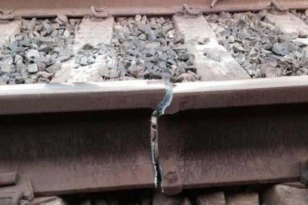
The main objective of the project is to develop a system capableof detecting cracksalongrailwaytracksusingan IRsensorandtransmittingthedetectedcrackcoordinates to the cloud via a GPS module. The block diagram depictedinFig-2illustratesthekeycomponentsandtheir interconnectionswithinthesystem.
IR Sensor: The IR sensor serves as the primary crack detection component. It is positioned strategically along the railway track to continuously monitor its surface for anycracksorabnormalities.Whenacrackisdetected,the IRsensortriggersthesystemtoinitiatefurtheractions.
MotorDriverandMotor:Themotordriverandmotorare likely utilized as part of a mechanism to facilitate movementalong therailwaytrack.Thismovementcould be for the purpose of deploying the IR sensor along the track or for any other operational requirements of the system.
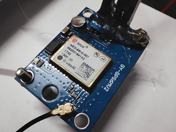
GPS Module: The GPS module integrated into the system provides accurate geographical coordinates of the location where the crack is detected. These coordinates are essential for precisely identifying the location of the crackalongtherailwaytrack.
Cloud Connectivity: Once a crack is detected and the corresponding GPS coordinates are obtained, the system utilizescloudconnectivitytotransmitthisinformationto thecloudinfrastructure.Thiscommunicationenablesthe real-time sharing of crack detection data with relevant stakeholdersandauthorities.
Overall,thesystemaimstoenhancerailwaysafetyby enabling the timely detection and communication of cracks along railway tracks, thereby facilitating prompt maintenancetomitigatetheriskofaccidents.
Selecting the appropriate sensor for a specific application canindeedbeachallengingtask,andinthecaseofdetecting cracks along railway tracks, it’s crucial to choose a sensor that offers high efficiency and reliability. After careful consideration and evaluation, the decision was made to utilizeaninfrared(IR)sensorforthisprojectduetoseveral reasons:
Suitability for Surface Detection: IR sensors are well-suited for surface detection applications, making them ideal for detecting cracks along railway tracks. They can effectively identifychangesorirregularitiesinthesurfacetexture,such ascracks,whichisessentialforensuringaccuratedetection.
Sensitivity to Changes in Surface Temperature: Cracks on railway tracks can cause temperature variations due to factors like friction and stress. IR sensors are sensitive to changes in surface temperature, allowing them to detect thesevariationscausedbycracksmoreeffectively.
Non-contact Operation: IR sensors operate in a non-contact manner, meaning they do not physically touch the surface being monitored. This feature is advantageous for railway track monitoring as it minimizes wear and tear on the sensorandreducestheriskofdamageormalfunction.
Cost-effectiveness: IR sensors are generally cost-effective comparedtoothertypesofsensorswithsimilarcapabilities. This aspect is crucial, especially for projects with budget constraintsorscalabilityconsiderations.
Robustness and Durability: IR sensors are known for their robustness and durability, making them suitable for deployment in harsh environmental conditions typically encountered along railway tracks, such as temperature variations,dust,andvibration.
ByselectinganIRsensorforcrackdetection,theproject team aims to ensure the efficient and reliable operation of the system while effectively addressing the challenges associatedwithrailwaytrackmonitoring.Thischoicealigns with the project’s objectives of enhancing railway safety through timely detection and communication of cracks for proactivemaintenanceandrepairactions.
International Research Journal of Engineering and Technology (IRJET) e-ISSN: 2395-0056 Volume: 11 Issue: 04 | Apr 2024 www.irjet.net
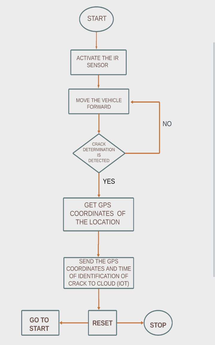
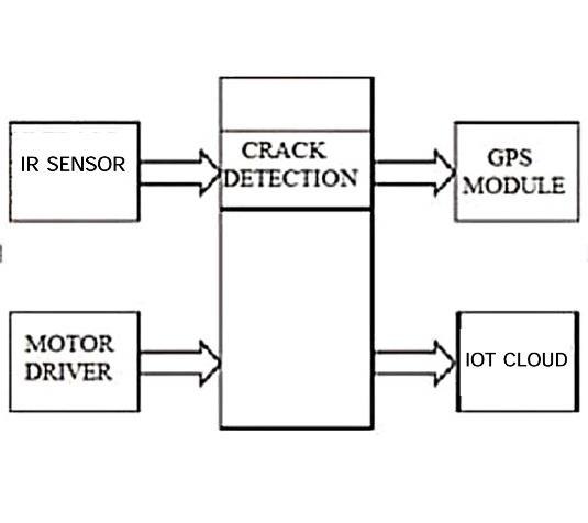
Fig -3:WorkFlowBlockDiagram
TheFig3depictstheworkflowdiagramofthemodel
Theprocessbeginsasfollows:
a)Thecarmovesforwardandbeginstodetectthecrack
b)Ifthecrackisnotdetected,itmovescontinuously.
c) If the crack is detected, the GPS module sends a signal toobtainthecoordinates
d) The coordinates are received by the GPS receiver wherethesignalissentbytransmitter
e) The At89s52 microcontroller controls the system’s overalloperation
f)Afterreceivingthecoordinates,thedata,includingthe locationandtimeofdetectionofcrackisstored
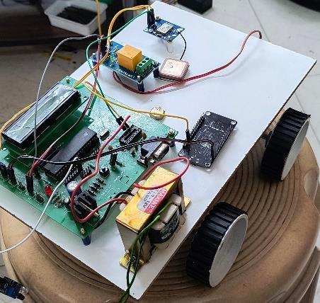
The primary aim of this model is to efficiently detect faults on railway tracks, particularly cracks, through regular inspections. The system employs a vehicle propelled by a motor and motor driver assembly. Detection of cracks is achieved using infrared (IR) sensors, while the precise location of the faults is determined via a GPS module. By integrating these technologies, the model ensures comprehensivecoverageoftherailwaynetwork,facilitating earlyidentificationandtimelymaintainanceoftrackdefects. This proactive approach enhances railway safety and operational reliability, mitigating the risks associated with track failures. Furthermore, the automated nature of the system reduces reliance on manual inspections, improving efficiency and reducing labor costs. Overall, the model represents a significant advancement in railway track maintenance, offering a reliable and scalable solution for ensuringtheintegrityandsafetyofrailinfrastructure.
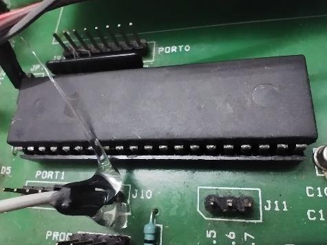
An 8-bit chip that is widely used is the AT89S52 microcontrollermadebyAtmel.Withits256RAMbytes,32 I/O pins, and 8KB of Flash memory, it can be used in a variety of embedded applications. Its architecture, which is compatiblewiththe8051,allowsittosupportawiderange of peripherals and communication protocols, enabling flexible designs for consumer electronics, automotive systems,andindustrialautomation.
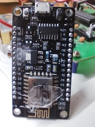
An open-source development kit and firmware called Node MCU is useful for creating Internet of Things applications.ItmakesitsimpletoprototypeInternetof Thingsdevicesbyintegratingwithascriptinglanguage based on Lua and using the ESP8266 WiFi module. Its integrated USB-to-serial connectivity makes troubleshooting and programming easier. Numerous sensors and actuators are supported by Node MCU , enablingawiderangeofIoTapplications.Becauseofits compatibility with the Arduino IDE, a large developer community can provide tutorials and libraries. Furthermore, both experts and enthusiasts can use Node MCU due to its tiny form factor and inexpensive cost, which speeds up the development and implementation of Internet of Things solutions for home automation, sensor monitoring, and other applications.
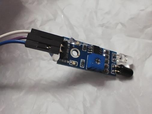
Aninfrared(IR)sensorpicksupinfraredradiationthat things release into space. It is made up of a receiver thatpicksuptheinfraredradiationandanemitterthat emits it. The infrared radiation is blocked by an object thatentersthesensor’sdetectionrange,whichmodifies the output of the receiver. Infrared sensors are widely utilised in many different applications, such as remote controlsystems,objectandmotiondetection,proximity sensing, and more. They are used in robotics, automateddoors,burglaralarms,andsecuritysystems. Because of their adaptability, affordability, and dependability,theyare essential tomoderntechnology foruseinbothconsumerandindustrialsettings.
A GPS module, also known as a global positioning system module, is a device that uses signals from satellites in orbit above the Earth to pinpoint its exact location as well as its velocity and time. It usually consists of a processing unit, an antenna, and a receiver. The latitude, longitude, and altitude of the module are determined by the receiver by gathering signals from several satellites. These modules are commonly utilised in many different applications, such as fitness trackers, drones, cellphones, and automobile navigation systems. They enable users to navigate, track assets, carry out location-based services, and conduct surveys by providing precise positioning information. Since GPS modules provide accurate and up-to-datelocationdataforavarietyofuses,theyhave becomeindispensableintoday’stechnologicalworld.
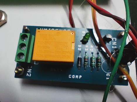
Relays are electrically operated switches that mechanically regulate the switching mechanism through the use of an electromagnet. Usually, an iron core with a coil of wire coiled around it is used. When thecorebecomesenergised,amagneticfieldiscreated that pulls an armature to make or break electrical contacts. Relays are widely utilised in many different applications,including ashomeappliances, automobile systems, telecommunications, and industrial automation. They allow low-power signals to reliably
International Research Journal of Engineering and Technology (IRJET) e-ISSN: 2395-0056
Volume: 11 Issue: 04 | Apr 2024 www.irjet.net p-ISSN: 2395-0072
manage high-power devices by establishing isolation between the control and load circuits. Diverse types of relays, including reed relays, solid-state relays, and electromechanical relays, are suitable for diverse applications depending on attributes including dependability, power handling capacity, and switching speed.
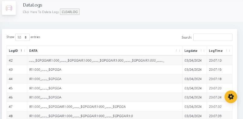
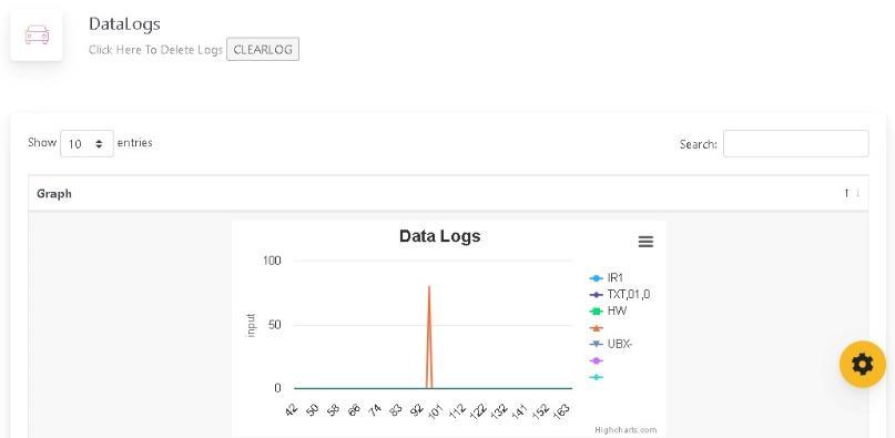
Our model is instrumental in identifying cracks, and once detected, the coordinates are transmitted to the cloudthroughaGPSmodule.Figures9and10illustrate both the time of crack detection and provide a graphicalrepresentationofhowthedataistransmitted tothecloud.
In conclusion, the initiative to address the pervasive issue of railway accidents in India through the integration of GPS systems, sensor technology, and IoT modules presents a comprehensive and proactive approach to enhancing railway safety. The focus on real-time crack detection, facilitated by the collaboration of these technologies, offers a promising solution to mitigate the risks associated with track faults, particularly fractures, which often lead to fatalities.
By leveraging GPS systems in tandem with sensor technology,theinitiativeaimstoaccuratelyidentifythe preciselocationsofrailwaytrackcracks,enablingswift intervention by railway authorities. The utilization of Node MCU IoT modules for data gathering and cloudbased transmission ensures seamless communication and efficient processing of critical information. Additionally, the incorporation of At89s52 microcontrollers supervises the overall operation, ensuring smooth integration and synchronization of diversecomponents.
The significance of this Initiative lies in its ability to provide railway authorities with timely and actionable insights, empowering them to implement preventive measures such as temporary closures or immediate track maintenance. By leveraging real-time data and cloud-based infrastructure, authorities can proactively addresspotentialrisks,therebyreducingthelikelihood of accidents and enhancing overall railway safety standards.
Furthermore,theinitiative’semphasisoncollaboration and technological innovation underscores a proactive approach towards addressing complex challenges within the railway sector. By harnessing the power of emerging technologies, such as IoT and cloud computing, the initiative demonstrates a commitment toleveragingmodern solutionstosafeguard passenger livesandimprovetransportationinfrastructure.
In essence, the integration of GPS systems, sensor technology, IoT modules, and microcontrollers represents a transformative step towards enhancing railway safety in India, signaling a shift towards proactive risk management and the adoption of innovativesolutionstoaddresslongstandingchallenges withinthetransportationsector.
[1]A.Rizvi,P.KhanandD.Ahmad,"Crack DetectionIn Railway Track Using Image Processing", International Journal of Advance Research, Ideas and Innovations in Technology.,vol.3,no.4,2017.
Volume: 11 Issue: 04 | Apr 2024 www.irjet.net
[2] S. Srivastava, R. Chaurasia, S. Abbas, P. Sharma and N. Singh, "Railway Track Crack Detection Vehicle", International Advanced Research Journal in Science, Engineering and Technology, vol. 4, no. 2, pp. 145-148, 2017.
[3]K.BhargaviandM.JanardhanaRaju"RailwayTrack Crack Detection Using Led-Ldr Assembly “, International Journal of Advanced Research in ElectronicsandCommunicationEngineering(IJARECE), vol.3,no.9,pp.1230-1234,2014.
[4]B. Siva Ram Krishna, D. Seshendia, G. Govinda Raja, T. Sudharshan and K. Srikanth, "Railway Track Fault Detection System By Using IR Sensors And Bluetooth Technology", Asian Journal of Applied Science and Technology(AJAST),vol.1,no.6,pp.82-84,2017.