
Volume: 11 Issue: 04 | Apr 2024 www.irjet.net p-ISSN:2395-0072
Volume: 11 Issue: 04 | Apr 2024 www.irjet.net p-ISSN:2395-0072
Darshan Mahajan1 , Deepraj Mokal2 , Rajesh Tirlotkar3 , Prof.Amol J. Ghude4
1,2,3Bachelor of Engineering, Mechanical Department, Datta Meghe College of Engineering, Airoli 4Professor, Mechanical Department, Datta Meghe College of Engineering, Airoli
Abstract - This study presents the design, analysis, and fabricationprocessofanoutboardbrakingsystemforanAllTerrain Vehicle (ATV). The outboard braking system offers several advantages, including improved cooling efficiency and reduced unsprung weight compared to traditional inboard braking systems. The design phase involves conceptualization, component selection, and CAD modeling to meet performance and safety requirements. Finite Element Analysis (FEA) is employed to assess the structural integrity and thermal performance of the braking componentsundervariousoperatingconditions.Fabrication techniques such as machining, welding, and assembly are utilized toconstruct the prototype system. The experimental evaluationincludesperformancetestingonatestrigandonfield trials to validate the functionality, reliability, and durability of the outboard braking system. Results demonstrate the effectiveness of the proposed design in enhancing braking performance and overall vehicle dynamics, thus contributing to the advancement of ATV technology.
Key Words: All-Terrain Vehicle, Outboard Braking, CAD modelling, Fabrication, Braking performance
1.INTRODUCTION
TheIndianautomotiveindustryisoneofthelargestinthe world. ATV (All-Terrain Vehicle) is one of the fastest growing segments in the automobile industry. ATVs can handle a variety of terrains and are used in diverse activities such as agriculture, off-road racing or leisure. The use of ATVs for racing is becoming increasingly popular.
One key concern with the ever increasing speeds of these vehiclesissafety.Thisisnotonlya concernforthe riders but also for track side personnel and spectators. With the averagemassofanATV beingintheregionof250kgand capable of reaching speeds in excess of 100 kmph, it becomes clear that stopping these vehicles safely and quickly is no simple task. A system capable of doing so reliablyunderharshandvariedconditionsisrequired.
TheprimaryformofbrakingusedinATVsiscurrentlythe Outboard braking system. This system is efficient when usedasanin-boardsystemindryconditions.
However, its effectiveness is reduced during off-road activities such as racing, where the likelihood of encountering water and mud is high. This can cause the disc to become wet and covered in debris, reducing the braking effectiveness significantly. A solution to this problemistouseanoutboardsystem,whichcanbesealed andisolatedfromtheatmosphere,enablingittoworkina cleananddryenvironment.
This is a proven system in the motorcycle industry and could be an effective method of braking for ATVs. However, as of now there is no specific literature or documented information on the design and analysis of an outboard brake system for an ATV. This paper aims to provideinformationtofuturedesignersonthewaystodo thiseffectively.
ThefollowingareissuesthatarisewhenanATVinstallsan inboardbrakingsystem.
1. Disc Performance Affected by Oil leaking: The inboard braking system has difficulties as a result of gearbox oil leaking, which makes the disc greasy. This problem not only impairs braking effectiveness but also promptsquestionsaboutdependabilityandsafety.
2. Subsystem Mounting Issues: The design and integrationoftheinboardbrakingsystemaresignificantly hampered by subsystem mounting issues, such as engine mounting.Complexengineeringchallengesareinvolvedin ensuring appropriate alignment and stability while accommodating multiple components within the restrictedavailablespace.
3. Excessive Cost of Brake Hub: The inboard braking system faces financial difficulties because of the brake hub'sexorbitantcost.Exorbitantproductionexpenses.
These issues collectively impede the efficiency, reliability, and cost-effectiveness of the inboard braking system, demandinginnovativesolutionsandcarefulconsideration indesignandimplementationprocesses.
International Research Journal of Engineering and Technology (IRJET) e-ISSN:2395-0056
Volume: 11 Issue: 04 | Apr 2024 www.irjet.net p-ISSN:2395-0072
The mechanics of outboard brakes are simpler. Because the caliper and disc are easily accessible, repairs and maintenance may be completed more quickly and easily. This results in reduced maintenance expenses and reduced repair downtime. The benefits of outboard brakingareasfollows:
1.Due to their less complicated design, outboard braking systems are also less expensive to construct than inboard systems.
2. The packaging of outboard brakes within the vehicle's chassis is more flexible. They may be adjusted for best performance without affecting other vital parts because they are separate from the axle and differential assemblies. This is particularly beneficial for cars with complexdrive-trainsorsuspensionsystem.
3.The inherent cooling efficiency of outboard brakes is a significant benefit. The brakedisc'sopen location permits direct Brake fade is avoided by this airflow's effective removal of heat produced by friction during braking. An important problem where too much heat diminishes the efficiencyofthebrakingsystemisbrakefade.
4.With outboard brakes, inspecting the brake discs and padsvisuallyisquickandsimple.Thismakesitpossibleto identify wear and tear early on, which facilitates prompt maintenanceandavertspossiblebreakdowns.


The scope of an outboard braking system for an ATV includes enhanced braking performance[3], improved heat dissipation, increased durability, and potentially better weight distribution for improved handling. Additionally,suchasystemcouldoffereasiermaintenance accessandpotentiallyreducetheriskofbrakefadeduring prolongedorintenseuse.However,implementationwould
need to consider factors such as cost, complexity, and compatibilitywithexistingATVdesignsandregulations.
The outboard braking system for an ATV has several objectives,withoneoftheprimaryaimsbeingtoincrease controlandstabilityofthevehicle
raking system, which places the brakes outside of the wheel hub, reduce unsprung weight and improvehandlingandcontrol.
-terrain conditions, active braking and all-wheel locking may be required at an instant time. The outboard brakingsystemcanprovidemoreevenbrakingandbetter distribution of braking force, allowing for quicker and moreprecisestops.
The outboard braking system can enhance safety for the rider and others by improving control and braking performance, riders can avoid accidents and collisions, reducingtheriskofinjuryordamagetothevehicle.
Themaincomponentsoftheoutboardbrakingsystemare asfollows:
1.BrakeCalipers:
In Outboard Braking System, the brake calipers are mounted on each wheel outside the ATV chassis. The caliper contain the brake pads and are responsible for squeezingtheagainsttherotortosloworstopthevehicle.
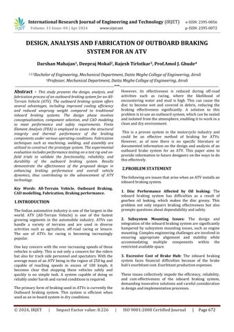
2. BrakeMastercylinder:
The Brake master cylinder is responsible for generating the hydraulic pressure, necessary to activate the brake system. It is mounted on the ATV chassis using the brake mastercylindermounts.
3. Brakelines:
Brake lines connect the brake caliper to the brake master cylinder, transferring the pressure necessary to activate thebrakesystemthroughthebrakefluid.
4. BrakeRotors:
The Brake disc is designed according to its mounting position on wheel hub. Also to maximize the heat flow through the pad actuating area and to remove any debris stuck between brake disc and pad , Proper slotting are made on disc. Even the padding area is increased to improveefficiencyofbraking.
5. BrakePedal:
Thebrakepedalisusedtoactuatethebrakesystemand generate the hydraulic pressure necessary to activate the brakecalipers.
International Research Journal of Engineering and Technology (IRJET) e-ISSN:2395-0056
Volume: 11 Issue: 04 | Apr 2024 www.irjet.net p-ISSN:2395-0072
6. BrakeFluidReservoir:
Thebrakefluidreservoirsstoresthebrakefluidusedto generate the hydraulic pressure necessary to activate the brakesystem.
The working of an outboard braking system is similar to that of a conventional braking system, with the primary difference being the brake components. Here are the general steps involved in the working of an outboard brakingsystem:
1. When the driver presses the brake pedal,itactivates the brake master cylinder, which creates pressure in thebrakelines.
2. The brake fluid flows through the brake lines to the brake calipers, which are located on each wheel hub outsidethechassis.
3. The brake calipers hold the brake pads and use the pressurefromthebrakefluidtoclampthepadsonto the brake rotors, creating friction and slowing or stoppingthevehicle.
4. As the brake pads create friction against the rotor, heatisgenerated.Insomeoutboardbrakingsystems, cooling ducts or other features may be used to dissipatetheheatandpreventbrakefade.
5. Once the brake pedal is released, the pressure in the brakelinesisreleased,andthebrakecalipersrelease thebrakepadsfromtherotor,allowingthevehicleto movefreelyagain.
Overall, the working of an outboard braking system is designed to provide reliable and effective braking performance, while also minimizing the weight and complexityofthebrakingsystem.
Calculation for braking torque
Mass=285kg
Deceleration=0.8g=0.8X9.8=7.84
Heightofcentreofgravityofvehicle=22inch=0.5588m
Wheelbase=58inch=1.4732m
Weightratio=x=0.4(40:60)
TyreRadius=11.5inch=0.2921m
μroad &tyre =0.7
μpads&rotor =0.3
Refficiency = (Ri+Ro) (Refficiency=meanradiiofpads)
Ri=innerradiiofdisc
Ro=outerradiiofdisc
Refficiency =0.0715
PedalRatio=7:1
Dynamic Load Transfer (DLT)
DLT= = =848.40N
Load on Front Axle :
=(weightofvehicleXx)+DLT
=(mgXx)+DLT
=(285X9.81X0.4)+848.40
=1966.74N
Load on Rear Axle :
=(weightofvehicleX(1-x))-DLT
=(285X9.81X0.6)-848.40
=829.11N
Wheel Torque on each wheel
1. Front :
μroad&tyrexLoadonFrontAxlexTyreRadiix
=0.7x1966.74x0.2921x =201.06Nm
2. Rear :
μroad&tyrexLoadonRearAxlexTyreRadiix
=0.7x829.11x0.2921x
= 84.764Nm
Calculation for pressure generated by Master Cylinder
1. Pressure in lines = =
International Research Journal of Engineering and Technology (IRJET) e-ISSN:2395-0056
Volume: 11 Issue: 04 | Apr 2024 www.irjet.net p-ISSN:2395-0072
= = 7367824.56N/m2
2. Clamping Force
= x(Dcaliper)2 xNo.OfPiston
=7367827.56x x(0.030)2 x2
=10416.02N
Calculation for braking torque
=ClampingForcexμpad&rotorx Refficiency
=10416.02x0.35x0.0715
=260.66Nm
Braking torque > Wheel torque
260.66 Nm > 201.06 Nm
Thereforevehiclewillcomeatrest.
Thermal Calculation :
Kinetic Energy for Vehicle:
= xmxv2
m=285,v=60km/hr,x=0.6(StaticFactor)
K.E.= xmxv2×x
= x285x16.672 x0.6 =23760J
Stopping Time for Vehicle
v=u+at
0=16.67+(-0.8×9.81)×t
t=
t=2.125
Braking Power:
Pb= = =11181.17W
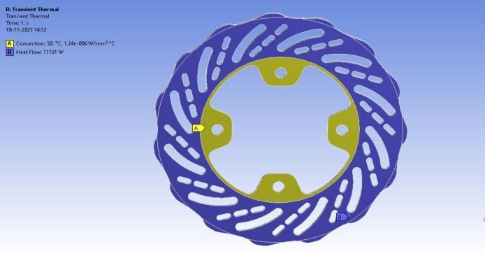
Heat Flux :
Q= A=Areasweptbypads
Q= =688326.15W/m2
Calculated heatflux is approximately equal to the derived heatfluxfromAnsysworkbench(TransientThermal).
9. ANALYSIS
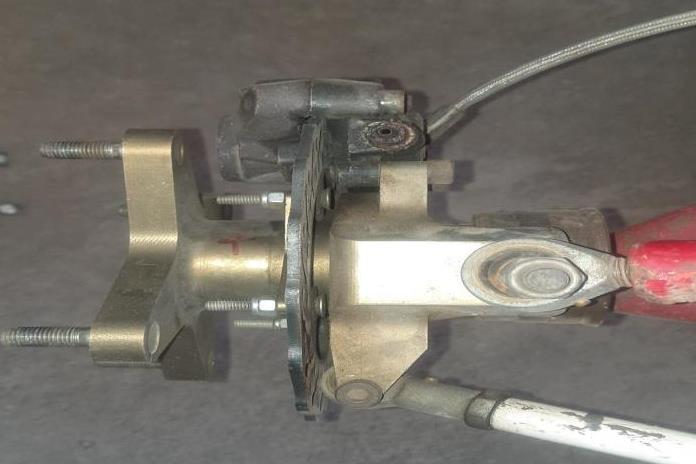
Master Cylinder Mount Analysis
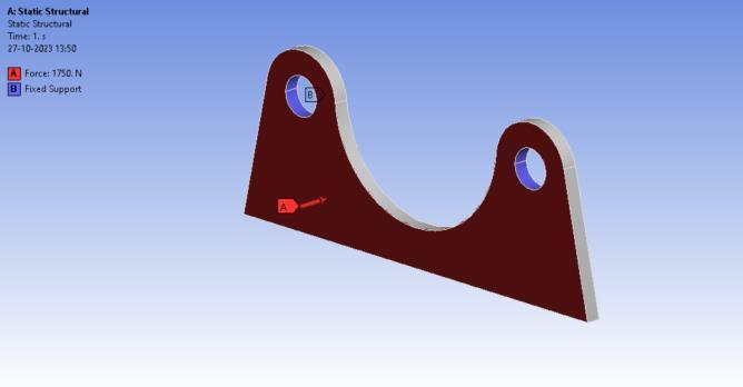
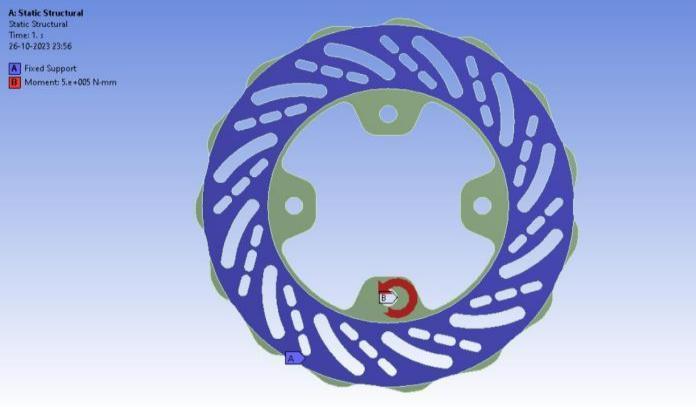
Fig -2:BoundaryCondition
Fig -3:EquivalentStress
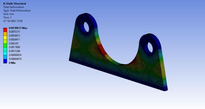
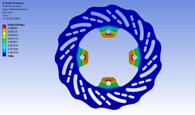
Fig -4:TotalDeformation
International Research Journal of Engineering and Technology (IRJET) e-ISSN:2395-0056
Volume: 11 Issue: 04 | Apr 2024 www.irjet.net
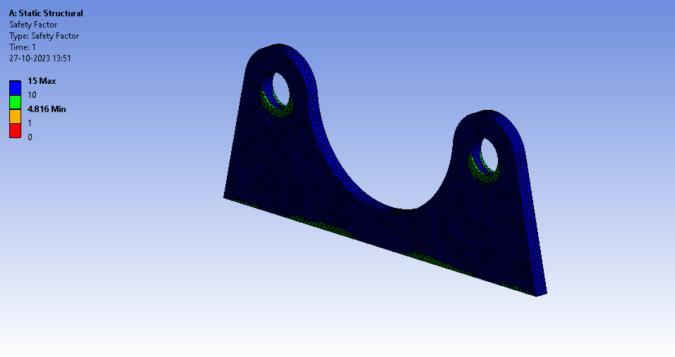
-5:Factorofsafety
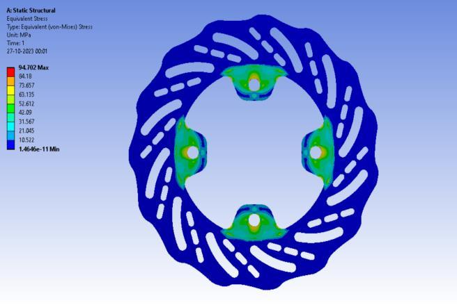
-8: Equivalent Stress
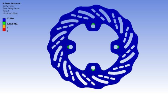
-10:Factorofsafety
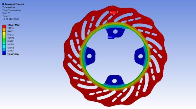
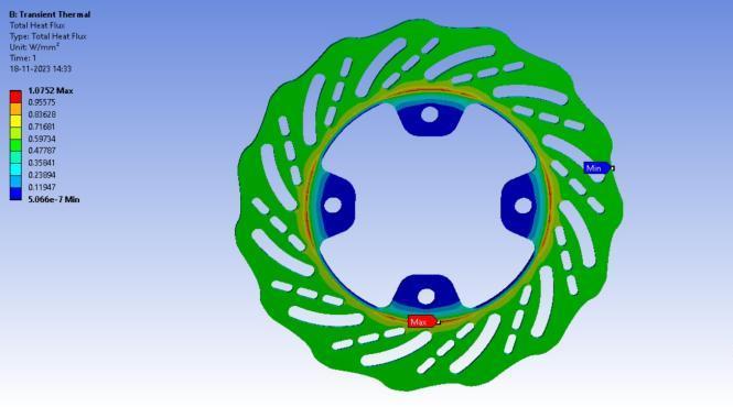
:TotalHeat
International Research Journal of Engineering and Technology (IRJET) e-ISSN:2395-0056
Volume: 11 Issue: 04 | Apr 2024 www.irjet.net p-ISSN:2395-0072
Pedal Analysis
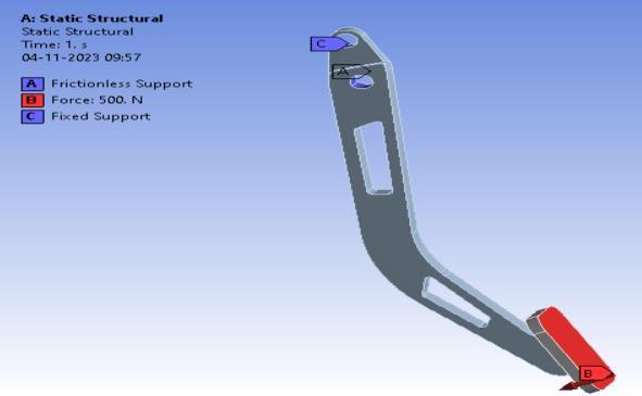
Fig -13:BoundaryConditions
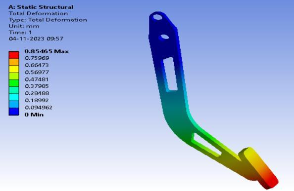
Fig -14:TotalDeformation
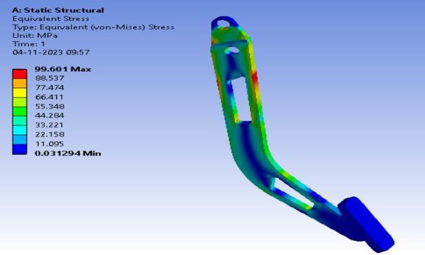
Fig -15:Equivalentstress
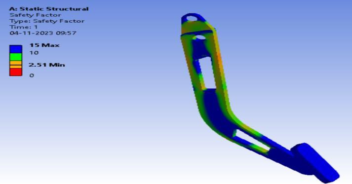
Fig -16:Factorofsafety
Table of Material
Table - 1 : MaterialTable
Components
Specification
DualMasterCylinder 19.05mmBoreDiameter
BrakeDiscDimension andMaterial 176mmx3.5mm
StainlessSteel420
BrakePedalRatio 7:1
BrakeFluid DOT4
CaliperPistonArea 1017.87mm2
FluidLines 4mmTeflonID(Steel Braided)
Tosumup,allterrainvehicles(ATVs)benefitgreatlyfrom the outboard braking system, which improves performance, safety, and maneuverability. We have demonstrated via our study how well it distributes braking forces, lowers the possibility of rollovers, and improves control on difficult terrain. Its modular design also makes maintenance and modification simple, which appeals to ATV fans even more. The outboard braking system surely offers a potential way to improve ATV capabilitiesinavarietyofoff-roadsituations,eventhough more research may be required to examine its long-term durabilityandcost-effectiveness.
[1] “Brake System Design and Analysis for All-Terrain Vehicle” Authors: Rajashekhar D Biradar, M. K. Ramesh, and Mahesh Gouda Published in: International Journal of Engineering and Technology, 2013
[2] “A Review on Braking System of All-Terrain Vehicle (ATV)” Authors: Rahul T. Chaudhari and P. A. Patil Publishedin:InternationalJournalofEngineeringand InnovativeTechnology,2012
[3] “Performance Analysis of an Outboard Brake System in All-Terrain Vehicles (ATVs)” Authors: D. I. Kamara, Y.Wang,andY.H.C.ManPublishedin:Proceedingsof The Institution of Mechanical Engineers, Part D: JournalofAutomobileEngineering,2018
[4] “Development of a Brake System for an All-Terrain Vehicle” Authors: K. A. Chirwa and R. N. Muleke Publishedin:InternationalJournalofEngineeringand Technology,2017
International Research Journal of Engineering and Technology (IRJET) e-ISSN:2395-0056
Volume: 11 Issue: 04 | Apr 2024 www.irjet.net p-ISSN:2395-0072
[5] Design and Analysis of Braking System of All Terrain Vehicle" Abhishek Salunkhe, Omkar Patil, Akanksha Patil. Publishedin: Journal ofResearchinMechanical Engineering Volume 9 ~ Issue 7 (2023) pp: 16-23 ISSN(Online):2321-8185.
[6] “Design and Analysis of Brake System for ATV Using CAD” Authors: Mohd Rizal, H. Fadzillah, and H. Amir Publishedin:ProcediaEngineering,2012
BIOGRAPHIES

DarshanVasantMahajan
BachelorofEngineering,Student ofMechanicalDepartment,inDatta MegheCollegeofEngineering, Airoli,NaviMumbai.


DeeprajKalyanMokal
Bachelor of Engineering , Student ofMechanicalDepartment,inDatta Meghe College of Engineering, Airoli,NaviMumbai.


RajeshSantoshTirlotkar
Bachelor of Engineering , Student ofMechanicalDepartment,inDatta Meghe College of Engineering, Airoli,NaviMumbai.

Prof.AmolJ.Ghude
ProfessorinMechanical DepartmentofDattaMeghe CollegeofEngineering,Airoli,Navi Mumbai.