
International Research Journal of Engineering and Technology (IRJET) e-ISSN: 2395-0056
Volume: 11 Issue: 03 | Mar 2024 www.irjet.net p-ISSN: 2395-0072
International Research Journal of Engineering and Technology (IRJET) e-ISSN: 2395-0056
Volume: 11 Issue: 03 | Mar 2024 www.irjet.net p-ISSN: 2395-0072
Dattatraya Balasaheb Kad 1
1Lecturer, Department of Mechanical Engineering, Sharadchandra Pawar Institute of Technology Someshwarnagar Baramati Pune, Maharashtra, India
Abstract - A boiler is a container in which a fluid is heated until it changes into vapor or a high-temperature liquid. Heat is supplied in boilers through convection, radiation and conduction. There are two types of boilers: fire tubeboilersandwatertubeboilers.Here, weanalyzed a water tube boiler. It is very essential to optimize and study the heat transferring mechanism and their characteristics to study & also control the various thermal losses. In this work internal flow analysis of a super heater is done to study the heat transfercharacteristicsofsuperheaterusingaComputational FluidDynamics (ANSYS- FLUENT) package The CFD analysis provided fluid velocity, temperature, pressure, and wall fluxes, and especially we have concentrated on the inlet to outlet of the super heater of a boiler pressure drop. The Computational Fluid Dynamics (CFD) approach used here to solvemanyboilerproblemssuchas pressuredrop,parametric study andheat losses of super-heater analysis helped to study the possibilities of improve the heat transfer properties.
Key Words: CFD, Wall fluxes.
Theboileristhedeviceofapowerplantthatgenerates steambyburningavailablefuelsusedforpowergeneration. The super heater canworkas the heart of any boiler system. Continuoussupplyofthedesired amount of steamattherated pressure and temperatureis the main workofit.Super-heateristheheatexchangerinwhichheat istransferredfromfurnacegastothesteam,Becauseofthe improperheattransferbetweenfurnacegas&steamleads toproblemsofheating.Itreducedperformance,repetitive failuresinboilercomponentarecommonproblemrelated toanytypeofboilersystem.Super heatertubedamageis verycommonissueinboilers.Inthisworkwehavedone CFD analysis of super heater flow to study thermal parameter, to study and investigate the enhancement in heattransfercharacteristics.Temperaturedistributionin the watertubeboilerperformsvariousefficiencytesting and simulation of thermal flow inside in sugar factory boiler,Theanalysisofthetemperaturedistributionforany location inside the domain is conducted bysettingthe constanttemperatureandvaryingparameterssuchasmass flow rate of steam (kg/s), steam inlet temperature and depth of scale formation. The commercial CFD software used to control volume based technique to convert the variousgoverningequations,whicharesolvednumerically usingtheimplicitmethod.Thetemperaturedistributionin
the boiler tube isaffected by the manyvariablessuchas mass flow rate of steam (kg/s), steam temperature, feed waterpressure&temperature.Ifweincreasethemassflow rate of steam through the boiler tube,thenthere will be adecreaseintemperatureontheinnertubewall.Computer simulationisused tounderstandthethermal flowinthe boiler, solveoperationalproblems,and search for optimalsolutions. The thermal flow behaves inside the boiler was studied to make the study of heat transfer characteristics and minimize the all thermal losses. The workstudyperformsadetailedsimulationofcombustion andthermalflowbehaviourinsidethesugarfactoryboiler. ActualWorkingConditions
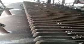
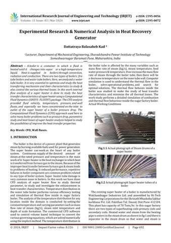
Theexistingsuperheaterofa boilerismanufacturedby Walchandnagar Industries Ltd. and assembled by Hi-Tech EngineeringCorporationsfortheShrinathMhaskobaSakhar karkhanaPvt.Ltd.PatethanTal:Daund,Dist:Pune-412104. Thisplanthascapacityof70Tons/hr.Inthissugarfactory therearetwotypesofsuperheatingcoilsprimarycoilsand secondarycoils.Heatedwater and steamfrom the heating pipeisentersinthesteamdrumasshowninfig1andthereis separator in the steam drum so that water and steam is
International Research Journal of Engineering and Technology (IRJET) e-ISSN: 2395-0056
Volume: 11 Issue: 03 | Mar 2024 www.irjet.net p-ISSN: 2395-0072
separated,below300°csteamisreheatandtheonlyabove 300°c steam flows in the super heater pipe this steam temperatureagainincreasedbyduetoheatingoffluegasesin theboilerdrum.Insugarfactorytherearetotal45numberof same super heating tubes present at the separator drum arrangement. The capacity is 70 Tons/hr steam is flow throughthesuperheatertubes.Samesteamflowrategets dividedin45numbersoftubes,sowehaveconsidersingle tubefortheanalysis.
Theobjectivesofworkareaslistedbelow.
1.Studyingthespeed,pressure,andtemperaturedistribution ofthesuperheaterthathelpstoidentifythereasonsforheat loss and determine the reduced heat transfer properties throughCFDsimulations.Tovalidatethepracticalresultwith CFDresult.
2.Parametricstudytoidentifyfeasibleandpracticalsolutions toimproveheattransferperformanceinasuperheaterby modifying various parameters in the system such as geometry,boundaryconditions,massflowrateofthesuper heater,diameterofthecoil,temperatureoftheinlet,thermal flow,etc.
Thepurposeofthisworkistoprovideanin-depthanalysisof superheatertubedefectsandimprovementssuggestedby variousauthorstoenhancetheheattransferproperties.The lossesreportedandquantifiedarealsoincluded.Thischapter willhelptoexplorethedifferentaspectsoftheheattransfer andthefluidflowofthesuperheatersection.Therefore,this chapterfocusesonthemodelandanalysisofthesuperheater toanalyzeandstudythethermalflowoftheboilertosolve theoperationalissues.
Saripalli and Masoud (1-2) presented a detailed descriptionofthermal-flow,combustion,andpossiblecauses of super heater tube rupture in the boiler. Exhaust gas temperature is in line with the real results of the infrared thermography inspection. This study helps industry in improvingboilerefficiency,reducingemissions,preventing superheatertuberupture,andunderstandingthethermal flowtransportwithintheboiler.TheCFDschemeappliedfor providesacomprehensivepictureofwhatisgoingoninside theboiler.Inmostcases,theproblemscanbeidentifiedanda solutioncanbedeveloped.ACFDanalysisprovidesfluidflow rate,pressure,temperatureandspeciesconcentrationacross the entire domain of the solution. During the analysis, boundary conditions (e.g. flow rate, inlet velocity) can be changed to see their impact on thermal-flow pattern or species concentration distribution. Several ideas were developedfromthisstudytoincreaseboilerefficiencyand reduce the thermal stress problem caused by the super heatertubes.
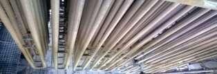
Jayakumar[3]reportedthatheattransferinahelicalcoil ishigherthanthatinacorrespondingstraightpipe.Itwas observedthatthevariationoflocalNusseltnumberalongthe length and circumference at the wall of a helical pipe. Movement of fluid particle in the helical pipe has been observed. CFD simulations are carried out for vertically oriented helical coil by varying coil parameterssuchas(i) pitch circle diameter (PCD), (ii) tube pitch & (iii) pipe diameterandtheirinfluenceonheattransferhasstudy.Many researchershaveidentifiedthatacomplexflowpatternexist insideahelicalpipeduetowhichtheenhancementinheat transferisfindout.Transitionfromlaminartoturbulentflow takes place at a Reynolds number higher than that for a straightpipe.CriticalReynoldsNumberandcurvatureratio givenbellow.Aplotof 〖Re〗crforthecurvatureratiofrom 0.01to0.25isgiveninFig.2.1Inthelowerrangeofcurvature ratios(1<0.05),allofthecorrelationsprovideapproximately thesamevaluefor 〖Re〗cr.TheperiodicbehaviorofNusselt numberattopandbottomsidesofthecross-sectionsalong the length of the pipe.The values ofNusseltnumber at the inner, outer, top and bottom along the periphery at given cross- section in the developing section. Fig.2.2 gives the variationofNusseltnumberaroundtheperipheryatvarious cross-sections, along the length of the helical pipe. In this analysis, a helical coil with a pipe of inner diameter (2r) 20mmandpitchcirclediameterof300mmwasconsidered. Analyses were carried out by changing the coil pitch. Coil withpitchof(i)0mm,(ii)15mm,(iii)30mm,(iv)45mmand (v)60mmwereanalyzed.Whenthecoilpitchiszero,local Nusseltnumbersatthebottomandtoppointsoncrossofthe peripheryarealmostthesame.Themagnitudeofdifference betweenthelocalNusseltnumbersatthebottomandtopat anygivencorrespondingcross-sectionthusincreases with increaseinpitch.However,variationoflocalNuforthecoils withpitchof45and60mmareidentical.Nusseltnumberon theoutersideofthecoilisfoundtobethehigheramongall other points at a specified cross-section, while that at the inner side of the coil is the lowest. However, the average Nusseltnumberisnotaffectedbythecoilpitch
Figure 3.1 CriticalReynoldsnumberpredictedby variouscorrelations[3]
International Research Journal of Engineering and Technology (IRJET) e-ISSN: 2395-0056
Volume: 11 Issue: 03 | Mar 2024 www.irjet.net p-ISSN: 2395-0072
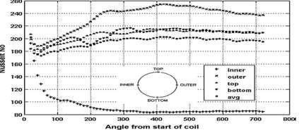
3.2 VariationofNualongthelengthcoil[3]
Shajikumar [5] presented an investigation on tube temperature distribution in a water tube boiler, performs detailed efficiency testing and simulation of thermal flow insideanindustrialboiler.Thesimulationswerecarriedout usingcommercialavailableCFDsoftware.Figure2.3shows thattemperaturevariesalongtheradialdistance.
The analysis of the temperature distribution for every locationinsidethedomainisconductedbysettingconstant heatfluxes,andvaryingparameterssuchasmassflowrateof steam,steaminlettemperatureandscalethickness.
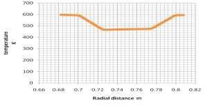
The distribution of the temperature in the boiler tube dependsonmanyfactorssuchasthemassflowrateofthe steam,thesteamtemperature,thefeedwatertemperature and the pressure. As the mass flow rate increases, the temperature in the internal tube wall decreases. This behaviorisduetothenon-proportionalreleaseofheatfrom thefluegastothesteam.Theabilitytoabsorbtheheatfrom highermassflowrateoffluegasisfasterthantheabilityto absorb steam at higher mass flow rate. As a result, the temperature of the flue gas must increase in order for the heat balance to be achieved. The inlet temperature of the steaminfluencesthethermalefficiencyofthethermalpower plant.Highersteaminlettemperaturewillincreasethermal efficiency and higher operating temperature will also increasescalegrowth.
AccordingtoBegem[6],boilertubefailuresarethemain causeoftoday’splantandhaveanegativeimpactonoverall plant performance. The heattransfer analysis used wasto
applysurfaceheatfluxtothetube’sinnerwallsurface,which willeitherprovideheatorremoveheatintheprocess.Then, thevectoroptionwasactivatedandavectorplotofheatflow wasshown.Duetothethermalfluctuationcausedbyslagand changeinoperatingconditions,alternatingstresseswerealso created.Theboilertubeswerecrackedandtheplantneedsto overhaul for maintenance purposes because of the leak generated by the cracks. The analysis was basedon a predominant simulation, which mainly focused on the underlyingcauseofboilertubefailureexposedtooperating conditions.Theheattransferwasappliedtotheinnerwallof thetube,whichwilleithersupplyorremoveheatin. There are several types of failure modes that a boiler tube may experience.Thesemodesincludestresscorrosioncracking (Pitting), water side corrosion (Corrosion), fatigue failure (Fatigue), overheating (Overcrowding), dissimilar metal weldingfatigue(MechanicalFatigue),anderosion(Erosion). In this study, the failure modes and the end cracks of the boilertubeduetodissimilarmetalweldingwereanalyzed. Therefore, data was collected and analyzed to identify the cause of the failure and to suggest a solution. The use of suggestioncanpreventthecrackoccurrenceinboilertube.It can also delay the process because of thermal properties. Preventing the crack will reduce the frequency of maintenance and therefore the cost of the operation will decrease
In this work, Bingzhi LI[7] presented a sub model to calculatethestructureoftheslagflow.Thissubmodelisused toreducetheheattransferinthecaseofsuperheatertubes. The deposition formed on the super heater tube may also causethecorrosionofthetubematerial.IntheKraftrecovery boilerfurnace,alkalirichdepositsaremoltenandflowdown thesuperheatertubes.Inthiswork,thesubmodelisapplied totheCFDmodelofsuperheatertubesection.Inparticular,it isusedtocalculatetheslagstructureontwotubebendsof one of the initial groups of tube banks of the first flue gas exposedtothefurnace.Theslagmodeltakesintoaccountthe deposition by inertia impaction and supposes all the depositingparticlesarefullymoltenandsteamtemperature in the super heater constant. The slag model provides thicknessdistributionandsurfacetemperaturedistribution oftheowingdeposionlayer.
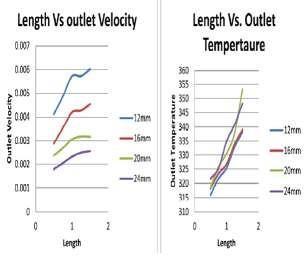
Khanorkar(10)presentedaCFDanalysisofverticaltube. Verticalcoppertubewithconstantcrosssectionareaisused to represent the medium through which water convection occurs.Inthiswork,naturalconvectionflowisstudiedand analyzedthroughverticalpipe.Thephysicalparametersof thetubesuchasdiameter,length,andheatfluxinfluencethe outletflowparameterssuchasvelocityandtemperature.The constantheatfluxisaboundaryconditionprovidedonthe entire surface of the tube. In this study, the outlet temperature and the outlet velocity increase as the tube length increases but decrease as the diameter of the pipe increases.Theoutlettemperatureincreasesbutthevelocity decreasesasshowninFig.3.4.
International Research Journal of Engineering and Technology (IRJET) e-ISSN: 2395-0056
Volume: 11 Issue: 03 | Mar 2024 www.irjet.net p-ISSN: 2395-0072
4.1 Actual working parameter
WorkingFluid- Steam
Inletmassflowrate- 0.4320kg/sec
InletTemperature- 573K
OutletPressure- 40Kg/cm2
ConstantWallTemperature– 873K
Specificheatofsteam-(Cp)– 2916.19 J/Kg-K
ThermalconductivityofSteam(K)-0.05194W/Kg-k
DensityofSteam(ρ)– 18.46Kg/m3
Dynamicviscosityofsteam(μ)– 1.985x10⁵
TotalLengthofSuperheaterpipe– 28.07m
Innerdiameterofsuperheaterpipe–0.041m
NumberofSuperheaterpipe fromthesteamdrum–45
TotalsurfaceHeatFlux– 89200W/m2
TotalheatingsurfaceAreaofSuperHeater–198m2
4.2 Computational Details
Todetermineturbulentflowinaboiler’ssuperheaterpipe, K-εmodelisusedinthestudy.Inthisstudy,thefinalvolume modelingwasperformedbyFluentsimulation(Fluent14.0). Thevelocityandthepressurefieldareconnectedusingsemi implicitmethod(SIMPLEalgorithm)forthepressurelinked equation.
4.2.1 Continuity equation

4.2.2 Momentum equation
Xcomponent
Ycomponent


4.3 Assumptions in the study
Thenumericalsimulationsusedinthisstudyarebasedon certain assumptions that have been made by other researcherswhileconductingsuperheaterflowanalyses.The following are the assumptions that have been used in the currentwork.Thefluidisconsideredtobenon-compressible with constant thermodynamic properties. The flow is consideredtobe3D,turbulent,steady,non-rotatingdueto theworkingfluidbeingsteam.Thesuperheatertubewallis assumedtohaveaconstanttemperature.No-slipvelocities areappliedatthewalls.Attheinlet,auniformmassflowrate isset.Thepressureoutletconditionattheoutletisassumed. Theturbulenceintensitylevelfortheflowis1.00%.
4.4. Experimental to numerical Conversion
Fig 4.3 illustrates how the experimental geometry is convertedtoanumericalmodel.Inthenumericalmodel,only theflowissimulated.Theexternalsections,walls,etc.asin theexperimentalsetup,havenotbeendrawnbecauseitis not necessary for numerical study. Therefore, here weare simulatingtheflowwithinthesuperheater.
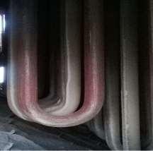
ExperimentalModel
International Research Journal of Engineering and Technology (IRJET) e-ISSN: 2395-0056
Volume: 11 Issue: 03 | Mar 2024 www.irjet.net p-ISSN: 2395-0072
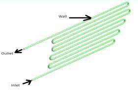
Fig.4.2NumericalModelinthisstudy
Here experimental model is converted in to numerical modelbyutilizingflowgoverningequations.
4.5Boundaryconditions
The numerical simulations in this study have been performedbasedonsomeassumptionsofotherresearcher while study the super heater flow analysis. Following are someoftheassumptionsonwhichthecurrentworkisbased.
a) Thefluidisassumedtobeincompressiblewithconstant thermo-physicalpropertiesandtheflowisassumedtobe3 dimensional, turbulent, steady and non-rotating. The workingfluidissteam.
b) Constanttemperatureisprescribedonthewallofsuper heatertube.
c) No-slipvelocityconditionsareappliedatallwalls.
d) Auniformmassflowrateandtemperaturearesetatthe inlet
e) Apressureoutletconditionisassumeattheoutlet.
f) A turbulence intensity level of 1% is assumed for the flow.
4.6MeshConversionsStudy
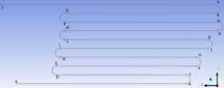
Fig:4.3 NumericalModelofSuperHeaterfor conversionsstudy
Inthissection,wesplitthegeometryintonighteenparts to analyze the different thermal parameters in the various parts of a super heater pipe,as shown in the Fig, the fluid flowbetweentheinletandtheoutlet.Inthissection,wedraw
the line inside the center of the super heater geometry, measurethetemperatureandthepressureatthedifferent parts of super heater pipe, measure the pressure and temperature,anddrawthecurvesforsectionST.
4.6.1 Various plots for all grids
To make sure that the numerical result is correct and valid, a thorough check of the grid dependency of the numericalsolutionswasdonebytakingintoaccount4grid systemswithhighnumberofgridpoints64932cells63900 cells50048cells42080cellsforsimulatingsuperheatertube. The plotted pressure, temperature at center line of super heatertubesurfaceNusseltnumber,skinfrictioncoefficient forsuper-heaterwallofthese4gridsystems.
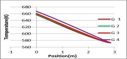
Fig.4.4 TemperaturePlotsforallgridsofSuperheater SectionAB.
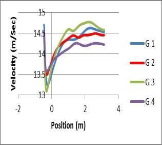
Fig.4.5 VelocityPlotsforallgridsofSuperheater SectionST
Figure 4.5 illustrates how the velocity changes at the bending part of the super heater. If a fluid moves with a straightpipewhichcurvesafterafewpoints,thebendingof the super heater causes the fluid particles to move in a differentdirection.
International Research Journal of Engineering and Technology (IRJET) e-ISSN: 2395-0056
Volume: 11 Issue: 03 | Mar 2024 www.irjet.net p-ISSN: 2395-0072
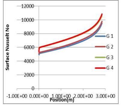
Fig.4.6 SurfaceNusseltnumberforallgridsofasuper heaterSectionAB
Thesurfacenusseltnumberisdecreasealongthelength of the super-heater and grid 3 and grid 4 show the same resultshowninthefig46.
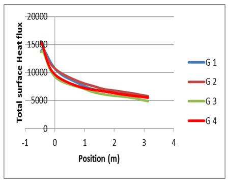
Fig 4.7 Totalsurfaceheatfluxforallgridsofasuper heaterSectionST
Thetotalsurfaceheatfluxdecreasesalongthelengthofthe super-heater,anditsmagnitudeisminimalatsectionSTof the super heater wall. The normal deviation of the temperatureandpressure,thesurfacenumberofthesurface, thetotalsurfaceheatflux,andtheskinfrictioncoefficientare asfollows:·50048–63900cells–42080(Grid2,Grid3,and Grid4)Tosavecomputerresourcesandmaintainabalance betweencomputationalefficiencyandpredictionaccuracy, wehaveselectedthegridof50048cellsforthesimulations. Thesesimulationshavebeenperformedonacomputerwith a2.3GHzfrequencyand2GBcorememory
4.7 Convergence History
The convergence criterion kept for continuity, momentum,kand equationsandenergyequationare TheSolutionisconvergedat164iterationsandgotfollowing results.5000iterationsaregivenatstartofthesolutionand solution converges at 164 numbers iterations. Parameters like temperature, velocity at outlet and surface nusselt numberandskinfrictioncoefficientmonitorsaresetinfluent monitorsetup.
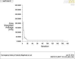
Fig. 4.8 Conversionshistoryofvelocityatoutletof superheater
Thevelocityvariationsalsooccuratthesuperheater outlet where it increases by 10 iterations and then decreasesby20iterationsuntilitreaches164iterationsas showninFig.4.8.
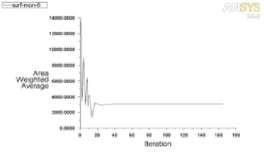
Fig. 4.9 ConvergencehistoryofNusseltnumberalong thewallofsuperheater
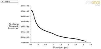
Fig. 4.10 ConversionsHistoryofskinfriction coefficientalongthewallofsuperheater
InFig.4.10,thesurfaceNusseltnumberincreasesfirstup to20iterationsandthendecreasesto20iterations.After20 iterations,theskinfrictioncoefficientincreasesagainupto 20 iterations. The skin friction coefficient decreases after iteration40andincreasesto164iterations.Figure4.10
International Research Journal of Engineering and Technology (IRJET) e-ISSN: 2395-0056
Volume: 11 Issue: 03 | Mar 2024 www.irjet.net p-ISSN: 2395-0072
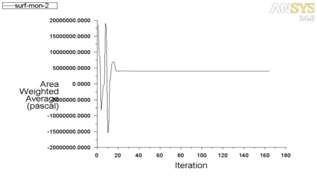
Fig.3.11 Conversionhistoryofpressureinletofsuper heaterpipe
Fromthefigure4.11itisobservedthatpressureatinletof superheaterisfluctuatefromiteration1toiteration20after 20iterationsitremainsconstant
5. RESULTS AND DISCUSSION
5.1. Various curves for super heater
Herevariouscurvesareplottedonthelinedrawninside thegeometryofthesuperheatertostudythermalflowinside superheater.
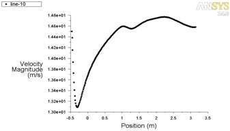
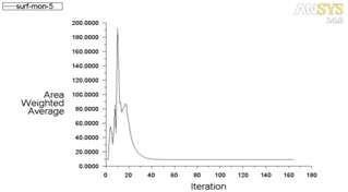
Fig. 5.2 WallskinfrictioncoefficientplotforSuper heatersectionST
Figure 5.2 shows that velocity increases along super heaterlengthandthenslightlydecreasesalongsuperheater length.Velocityishighestatthebendingpartofsuperheater pipes.Duetothecurvature,therewillbeanegativepressure gradient with the increase in pressure. Therefore, velocity decreasesnearconvexwallandincreasesontheoutsideside ofpipe.Skinfrictioncoefficientisalsohighatsuperheater bending section and decreases along super heater wall as showninFigure5.3.
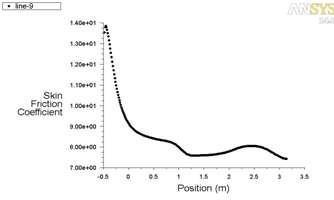
Fig. 5.3 SurfaceNusseltnumberplotforSuperheater sectionST
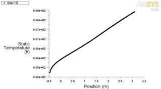
The nusselt (surface temperature) decreases from the inlet to the outlet of the super heater wall. The nusselt is minimal at the super heater at the outlet of the wall. As showninFigure5.4andFigure5.5,temperatureincreases with the super heater section ST. Temperature increases alongthesuperheatersectionofSTfrom865°Cto868°C.The highesttemperatureoccursatthesuperheateroutletat868 °C.
5.4
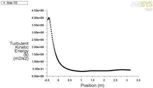
Fig. 5.5 Turbulentkineticenergyplotforsuper heatersectionST
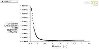
Fig 5.6 Turbulentdissipationrateplotforsuperheater sectionST
Figure5.5,figure5.6showsthatturbulentkineticEnergy, turbulentdissipationratedecreasesalongthelengthofsuper heater section ST. Turbulent kinetic energy and turbulent
International Research Journal of Engineering and Technology (IRJET) e-ISSN: 2395-0056
Volume: 11 Issue: 03 | Mar 2024 www.irjet.net p-ISSN: 2395-0072
dissipationrateismaximumatthebendingsectionofsuper heater.
Herevariouscontoursareplottedforasuperheaterto studyandunderstandthethermalflowinthepipetoresolve the operational problems. From figure it is observed that temperatureneartheU-tubebendfoundmorethananother part of the super heater. Temperature in the super heater section ST, SR, QR and PQ shows the same temperature. Temperatureisdecreasesalongthelengthofsuperheater. This fluctuation of temperature may cause the boiler tube leakage. As the super-heater is the heat exchanger it increases the temperature of the steam flowing inside the tubeandsothetemperatureofsteamincreasesfrominletto outlet due to the super heater wall is heated by flue gas around600°Celsius.Atcertainregionsuddentempvariation leadstothethermalembrittlement.Thismayleadstofatigue andcracksnearthejointofthetuberesultingintochangein shapeandcracksnearthecorners.
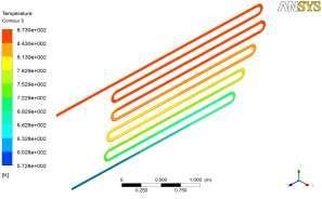
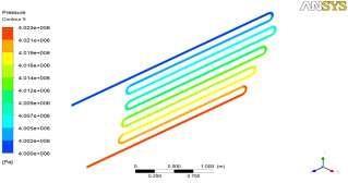
Fig.6.1showthatpressureisdecreasesalongthelength of super heater, maximum pressure occurs at inlet and minimumpressureatoutlet.Thepressuredropinvarious bentgeometries.Thepressuredropismoresignificantdueto flowseparationattheinnerwallinelbowsascomparedto bends.
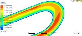
From the figure 6.4 and figure 6.5 it is observed that the velocityfluctuationtakesplaceattheU-bendingsection.The suddenincrementanddecrementofthevelocitytakesplace atthebendingpartofthesuperheater.Maximumvelocity observedatthebendingofasuperheater.Aboundarylayer isformedasthefluidentersthepipewheretheviscousforces areconfinedwhilethecoreisinviscid,likeinastraightpipe. Thesecondaryflowgeneratedbythecurvatureistherefore movingtheslowerfluidfromtheboundarylayerinwardsand thefasterfluidattheoutwards.Theinflowconditiongreatly affects the initial development of the flow with nonuniformityinwallshearstress,i.e.theshearislargestatthe inner wall before the maximum moves to the outer wall, appearing at two times larger distance for the first inlet conditionthanforthesecondone.
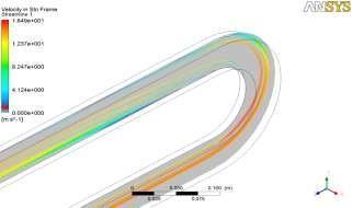
Fig.6.4. Contourofvelocitystreamlinealongthebending interiorofsuperheater
International Research Journal of Engineering and Technology (IRJET) e-ISSN: 2395-0056
Volume: 11 Issue: 03 | Mar 2024 www.irjet.net p-ISSN: 2395-0072
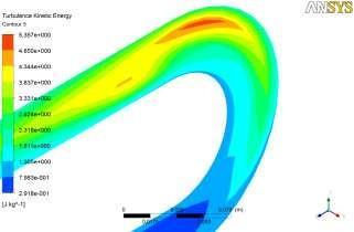
Contourofturbulentkineticenergyalongbending interiorofsuperheater
7. VARIOUS PLOTS OF SUPER HEATER FOR PARAMETRIC STUDY
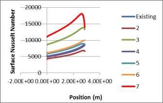
Fig.7.1 Nusseltnumbercomparisonsalongthewallofsuper heatersectionAB
Fromthefigures7.1isfoundthatifthemassflowrateof steamincreasesthennusseltnumberincreases.Ifthetotal numberoftubesofsuperheaterdecreasesthenmassflow rateandnusseltnumberincrease.Ifthediameterofsuper heatertubeincreasesthennusseltnumberalsoincreases.
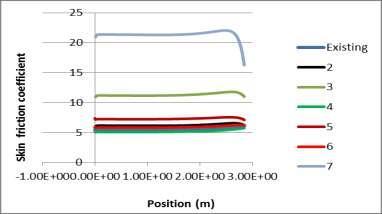
Fig.7.2 Skinfrictioncoefficientcomparisonsalongthewall ofsuperheatersectionAB
If the diameter of super heater decreases then skin frictioncoefficientalongthewallofsuperheaterincreasedue tothispressuredropalsoincreasedatthebendingsectionof superheater.Ifthemassflowrateofsteamdecreasesthen skin friction coefficient along the wall of super heater decreaseasshowninthefigure6.2.Thediameterofsuper heatertubeincreases,theheattransferalsoincrease.
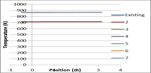
Fig.7.3 TemperaturecomparisonsofasuperheateratST
Itisevidentthatthemassflowratestronglyaffectsthe temperature distribution of the water tube boiler. From figure 7.3 is found that the increase of mass flow rate of steam through the boiler tube causes the decrease in temperature in the inner tube wall. This behavior occurs because of the heat release from flue gas to steam is not proportionalastheabilitytoabsorbheatfromfluegasfor highermassflowrateisfaster.Ifmassflowrateofsteamis increasedconsequenceofit,temperatureoffluegasmustbe increasedtomakeheatbalanceinequilibriumcondition.The higher steam inlet temp increases thermal efficiency but operating boiler with higher temperature has some disadvantages (i.e. to make steam inlet temp higher, more timeisrequired,andalsostrengthoftubematerialsshould be considered as higher temperature will degrade the strengthofmaterialandthermalconductivity).
International Research Journal of Engineering and Technology (IRJET) e-ISSN: 2395-0056
Volume: 11 Issue: 03 | Mar 2024 www.irjet.net p-ISSN: 2395-0072
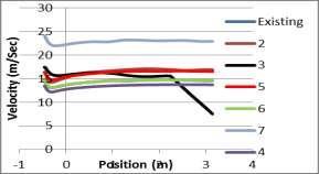
Fig.7.4 VelocitycomparisonsofasuperheatersectionST
Velocity of steam is depends on diameter of the super heater pipe.From figure 6.4it cleared that if diameter the super heater tube increased then velocity of a steam decreases.Alsoclearedthatvelocityofsteamismaximumat lowerdiameterofsuperheaterpipe.
8. Conclusion
The results and the study concluded that the heat transfer along the length of the super heater pipe and temperaturerangeisalsothesameatsectionsOP,QRandST. Therefore,itispossibletoreducethesuperheaterlengthto avoid thermal losses and financial losses. When mass flow rate of the steam in the super heater is decreased, the temperature of the steam inside the super heater tube increases.Whentotalnumberofthesuperheaterpipesare decreased by 5, the mass flow rate in the tube increases, resultinginanincreaseintheaveragenusseltnumber.This increasestheheattransferandtemperaturedecreases,which helpstopreventoverheatingofthesuperheater.Whenthe massflowrateincreases,thepressuredropincreasesandthe average nussselt number decreases. This increases the turbulentkineticenergyatthebendinginterior.
I would like to express my sincere appreciation to Shrinath maskoba sugar factory Management for their generous financial support of this research project. Their fundingplayedacrucial roleinthesuccessful executionof thisstudyandtheattainmentofourresearchgoals.
ThesupportprovidedbyShrinathmaskobasugarfactory Management enabledustoconductdatacollection,analysis, and interpretation, as well as cover expenses related to researchmaterials,participantrecruitment,andtravel,where applicable. Their investment in our work has significantly contributed to the quality and impact of our research findings.
Inconclusion,IamdeeplythankfultoShrinathmaskoba sugar factory Management for their financial support,
withoutwhichthisresearchwouldnothavebeenpossible. Theirinvestmentinourworkhasmadeasignificantimpact andhascontributedtoadvancementsinthefield.Iamtruly grateful for their commitment to supporting research and fosteringacademicgrowth.
Iamalsogratefultomyclassmatesandcohortmembers, especiallymyofficemates,fortheireditinghelp,late-night feedbacksessions,andmoralsupport.Thanksshouldalsogo tothelibrarians,researchassistants,andstudyparticipants fromtheuniversity,whoimpactedandinspiredme.
Lastly, I would be remiss in not mentioning my family, especiallymyparents,spouse,andchildren.Theirbeliefin me has kept my spirits and motivation high during this process. I would also like to thank my cat for all the entertainmentandemotionalsupport.
[1] Raja Saripalli, May 2005, “Simulation Of Combustion AndThermalFlowinanIndustrialBoiler”,ESL-IE-05-0542,ProceedingsoftheTwenty-SeventhIndustrialEnergy TechnologyConference,NewOrleans,LA.
[2] Rahimi Masoud, Abbas Khoshhal and Syed Mehdi Shariati, (2006), “CFD modeling of boiler tubes rupture ”JournalofAppliedThermalEngineering,26,2192-2200.
[3] J.S. Jayakumar, February 2009, “CFD analysis of single-phase flows insidehelicallycoiledtubes”Elsevier Ltd.,ComputersandChemicalEngineering34(2010)430–446
[4] Ajay N. Ingale, March 2012 , “CFD Analysis of Super heater in View of Boiler Tube Leakage”, International JournalofEngineeringandInnovativeTechnology(IJEIT) Volume1,ISSN:2277-3754.
[5] ShajikumarK.R,Sep-Oct.2012,“AnInvestigationon Tube Temperature Distribution in a Water Tube Boiler” IOSR Journal of Mechanical and Civil Engineering (IOSRJMCE)ISSN:2278-1684Volume2,pp45-50

Mr.KadD,B
LecturerinMechanicalEngineeringDepartment, Sharadchandra Pawar Institute of Technology Someshwarnagar,Baramati. Mobile-9096239395