
International Research Journal of Engineering and Technology (IRJET) e-ISSN: 2395-0056 p-ISSN: 2395-0072
Volume: 11 Issue: 03 | Mar 2024 www.irjet.net
International Research Journal of Engineering and Technology (IRJET) e-ISSN: 2395-0056 p-ISSN: 2395-0072
Volume: 11 Issue: 03 | Mar 2024 www.irjet.net
Aman Kumar1 , Ajay Singh2 , Nitin Barodia 3
1MTech Student, Dept. of Mechanical Engineering, Radharaman Institute of Technology and Science, Bhopal, M.P., India
2Professor, Dept. of Mechanical Engineering, Radharaman Institute of Technology and Science, Bhopal, M.P., India
3Professor, Dept. of Mechanical Engineering, Radharaman Institute of Technology and Science, Bhopal, M.P., India
Abstract - A CFD analysis of a shell and tube heat exchanger with a creative floral baffle design is shown in the abstract. The purpose of the study is to assess how the floral baffle affects convective heat transfer coefficient and heat transfer rate. Conventional baffles are frequently used in traditional heat exchangers, which may reduce their total thermal efficiency. The goal of the flower baffle is to improve the heat exchanger's thermal performance by drawing inspiration from the complex and effective forms seen in nature. The fluid flow and heat transfer properties are analysed and contrasted with a typical heat exchanger setup with traditional baffles using CFD simulations and numerical modelling. The heat exchanger fitted with the floral baffle performs at a much higher rate of heat transfer than the traditional design, according to the CFD study. Additionally, there is a discernible improvement in the convective heat transfer coefficient, suggesting a more effective heat exchange mechanism with lower thermal resistances. To sum up, the new floral baffle design shows a lot of promise for raising the shell and tube heat exchangers' heat transfer efficiency. This discovery has significant implications for sectors including power generation, chemical processing, andrefrigerationthat depend on heat exchangers. To verify the numerical results and determine if the suggested floral baffle design is practically applicable, more investigation and experimental validation are needed. If successful, the flower baffle could revolutionize heat exchanger technology, contributing to enhanced energy efficiency and sustainability across various industrial sectors.
Key Words: Shell and Tube Heat Exchanger, Nanofluid, Flower Baffle, Rate of Heat Transfer, ANSYS, CFD Analysis
Aheatexchangerisamechanicalapparatusthatrecyclesthe thermalenergycontainedwithin theworkingfluid.Theshell andtubeareaversatileheatexchangerduetoitsversatility in design and is extensively used in various sectors for cooling of turbine and compressor, oil industries, for refrigerationandairconditioning,andmanymore.Theshell
and tube heat exchanger consists of a collection of tubes contained within a shell. The baffle plates are one of the essential barriers situated within the shell to create turbulencewhichwillboosttherateofheattransferandalso offer support to the lengths of the tube. Various types of baffle plates are employed in the shell and tube heat exchanger,includinglongitudinalflowbaffles,impingement baffles (used to safeguard the bundle in cases of high entrancevelocity),andorificebaffles.Heatexchangersarean integral part of the sectors such as:power plants, process industries, oil refining and so on. Shell and tube heat exchangers (STHE) currently account for 40% of the equipment used in various industries. Hence, it is vital to prioritiseattentiononthisequipmentinordertoenhancethe functionalityofthisgadget. Bafflesandtubeconfiguration and their arrangement have a tremendous effect on the performanceofthiskindofheatexchanger.Onecanreferto commonsegmentalbaffleproblemsas:creationoffoulingin dead zone, producing high pressure drop because of dead zones, remarkable flow streams between shell and baffle, tube and baffle because of construction tolerance and decreasing the lifetime of the heat exchanger due to the vibration caused by the fluid flow across the tube bundle [1,2]. Gao et al. [3] studied the discontinuous baffle with differentanglesexperimentally.Theirresultshowthat40° helix angle is the best among the other investigated helix angles [3]. In an industrial research project in Tabriz, ZeyninejadMovassagetal.[4],employinghelicalbaffleas an alternativeofsegmentalbaffle,enhancedtheperformanceof the conventional shell and segmental baffle STHE by minimising the pressure drop and fouling. In another experiment,NematiTaheretal.[5]examinednumericallythe impact of baffle spacing for the helical baffle STHE. They employed baffles with angle of 20-degree. In the new technique by You et al. [6], they evaluated the computationallybasedontheporosityandpermeabilityidea in the range of Reynolds numbers from 6,813 to 22,326. Wang et al. [7] proposed floral baffled STHE in an experimentalresearchandcompareditsperformancewith ordinary segmental baffle. Wang et al. [7] examined thermohydraulicpropertiesofSTHEwithdifferenttypeofhelical baffle to decrease triangular zones. Helical baffle was
International Research Journal of Engineering and Technology (IRJET) e-ISSN: 2395-0056 p-ISSN: 2395-0072
Volume: 11 Issue: 03 | Mar 2024 www.irjet.net
introduced to remove the problems ofsegmental baffle. This wasfirstprovidedbyLutchaandNemcansky[8].Ozdenand Tari [9] did a study on tiny STHE in order to evaluate the influence of baffle spacing, baffle cut and shell diameter relationshipsoftheheattransfercoefficientandthepressure drop. They observed good agreement between acquired resultsandtheBell–-Delawaretechniqueresults.Leietal. [10]examinednumericallyandexperimentallythreeSTHE withdifferentbaffletypessuchascurrentsegmentalbaffle, singlehelicalbaffleandtwo-layerhelicalbaffle.Basedonthe obtained data, for the same pressure drop, the two-layer helical baffle exhibit superior performance than others. Zhangetal.[11]exploredtheangleofhelixbaffleonSTHE with the experimental test whereas Nemati et al. [5] performed it mathematically. Many publications were devotedtothestructureofthehelicalbafflesforexample: continuoushelicalbaffles[12],coupledhelicalbaffles[13], andcombinedmultipleshell-passhelicalbaffles[14].Gorman etal.[15]employeda corrugatedconstructioninaninner tube oftwintubeheatexchanger.Ahmedetal.[16]inthe numerical researchshowed the behavior offinned tube with variable configuration in a STHE. Based on their findings, wavy fin configuration exhibited superior performance than others[16].ElMaakouletal.[17]employedhelicalbaffleto optimizethedoublepipeheatexchanger.Aminietal.[18] studiedtheinfluenceofhelicalandsegmentaltubesheeton theperformanceofSTHE.Therearealotofinvestigations thatfocusonbafflesandtubessimultaneously.Liuetal.[19] reportedacomputationalsimulationoftheshellsideflowin rodbaffle heat exchangers with spirally corrugated tubes. Resultsarecomparedwiththoseinrod-baffleheatexchanger with plain tubes. Obtained results demonstrated that the thermo–hydraulicperformanceinspirallycorrugatedtubes issubstantiallyhigherthattherod-baffleheatexchangerwith plaintubes.Chenetal.[20]studiedtheinfluenceofsurface roughnessontheperformanceofatypicalheatexchanger, and found that the system's performance is somewhat improved.IntheworkofIbrahimetal.[21],thethermal-fluid behaviouroftheellipticaltubewasevaluatedinacrossover flowfortheaspectratioof0.25,0.33,0.5.Swainetal.[22] evaluated the heat transfer coefficient and pressure drop over the flat and elliptical tubes. In the investigation, the ellipticaltubebundlesshowsuperiorperformancethanthe flat tubes from the heat transfer viewpoint. In a similar investigation. He et al. [23] did a research on flow characteristicintheshellsideofaverticalSTHEwithcoupled helicalbaffleswithelliptictubes.Obtainedresultsshowed thattheheattransferrate,Nusseltnumber,frictionfactorand thermal performance factor of the elliptic tubes are 14.7–%16.4%,11.4–16.6%,29.2–36.9%and30–35%,greaterthan thoseofthecirculartubesaccordingly.Heatexchanger,and the shell side friction factor is decreased by 29.2–36.9%. Referredworkrevealsthattheelliptictubemayeffectively improve the heat transfer performance of non-Newtonian fluid flowing in the helical baffle heat exchanger when comparedtothecirculartube.Shrikantetal.[24]presenteda study on the impacts of different baffles configurations,
includingsingle,double,triplesegmental,helicalandfloral baffle, inside STHE. Based on acquired results, baffles improvedtheheattransferandpressuredrop.Forthesame massflowrateofshellside,heattransferrate,heattransfer coefficientandpressuredroparedeterminedtobethebest for single segmental baffles. In addition, zero stagnation zonesareidentifiedinhelicalbaffles,leadingtoreductionin fouling. Baffles have a vital purpose, as tubes support, providing shell-side desirable velocity distribution, and preventing from the tubes vibrating. In addition to assemblingeffects,itcangiveanessentialinfluenceonfluid flow andheattransferinshellsideofSTHE,as providingthe better local mixing and boosting the turbulence intensity [25],duetoestablishingthezigzagpatternamongthetube bundle.However,therearecertainunfavourableimpactson fluidflowandheattransferasgeneratingthefoulingbackof baffleplatesinthestagnationzoneandalongtheshellwall, producing a considerable pressure drop and creating separation flow near the baffle edge. Due to recent effect more pumping power is needed for the same heat load. Anotherproblemofbafflesconnectedtotheprovidingbypass streams and leakage streams and tube vibrations [2,26]. Therefore,itisvitaltopresentaninquiryonthebafflesto magnifythefavourableeffectandreducethebadeffect.Son and Shin [27] showed that the performance of STHE with helicalbafflesissuperiortothatofaconventionalSTHEdue togreaterfluidinteractionswiththetubesandminimising theshellsidestagnationzones.Inadditiontoofferedinquiry, one can found an investigation that deal with entropy production minimization concepts in heat exchangers in ordertoboosttheheatexchangerperformance[28].Work done by Ashraf Mimi Elsaid et.al. on shell and tube heat exchangerwithhelicalcoilwithvariedinclinationanglesand usageofnanofluidasaheattransfermedium[29].
In a prior experimental investigation (reference [29]), researchersfocusedonimprovingtheheatfluxofahelical coil heat exchanger by replacing the normal water with a nanofluid. The findings of the experiment revealed an increaseinheattransferrateandincreasedperformanceof the heat exchanger. When doing a computational fluid dynamics(CFD)analysisonahelicalcoilheatexchanger,the meshing of the model becomes intricate, consequently complicating the computation of findings. The helical coil designproducesturbulenceinthefluid,henceboostingthe heat transfer rate. However, to simplify the design and computation process, the helical coil heat exchanger was substitutedwithashellandtubeheatexchangercontaininga flowerbaffle.Theflowerbaffleservesthesamegoalasthe helical coil in increasing heat transfer. Moreover, this adjustmentgreatlyminimisesthecomplexityofthedesign. By utilizing the nanofluid, the heat transfer rate is significantlyincreased.Theshellandtubeheatexchangeris frequently deployed due to its versatility and adaptability to diverserequirements,makingitagreatcandidateforfurther development.Consequently,astudywasundertakento
Volume: 11 Issue: 03 | Mar 2024 www.irjet.net
analysetheperformanceofthenanofluidusingabasicmodel oftheheatexchanger.
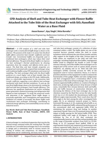
Design of shell and tube heat exchanger on ANSYS Workbench2022,withandwithoutflowerbaffle.Designthe geometry of flower baffles in Solid Works with 44 baffle platesarrangedinhelicalpath.Thenimportthisbaffleplates to the ANSYS 2022 to complete the geometry of shell and tube heat exchanger. Dimension of the heat exchanger is shownintable1andmodelisshownintheFig.1.
Table 1: Dimensions of Heat Exchanger
1
1: Model of the heat exchanger.
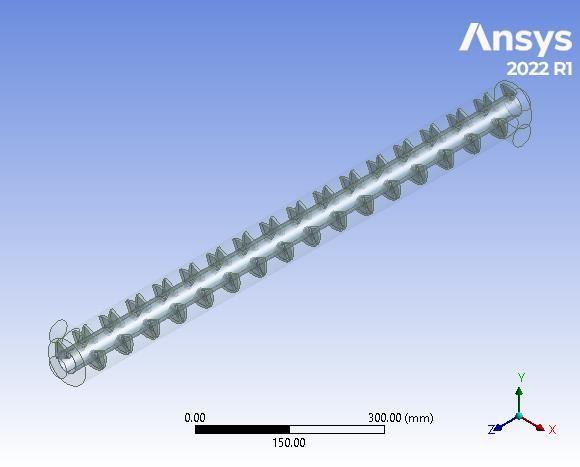
1.3 Meshing
The computational fluid dynamics (CFD) analysis of shell andtubeheatexchangerswithanewflowerbaffledesign
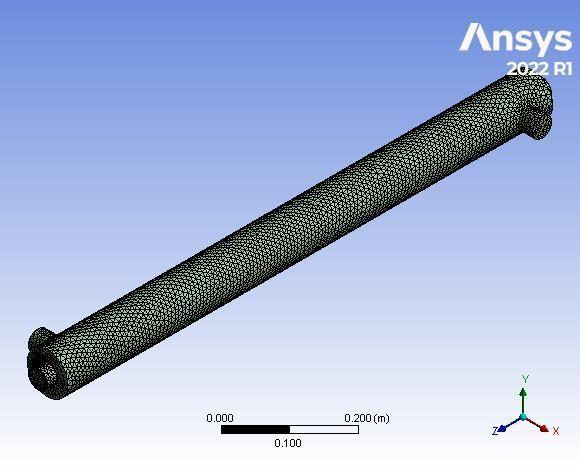
involves careful consideration of mesh generation and inflation techniques to accurately capture the intricate geometryandcomplexflowpatterns.Meshingplaysavital role in defining the reliability and efficiency of CFD simulations,sinceitdirectlyeffectsthesolutionqualityand computational cost. In this study, we address the issues associatedinmeshingtheflowerbafflegeometrywiththe surrounding fluid domain. A hybrid approach integrating structuredandunstructuredmeshingapproachesisutilised toappropriatelyresolvethecomplicateddetailsofthefloral baffle. The mesh resolution is chosen to create a compromise between accuracy and computational feasibility. Furthermore, suitable inflation is done to accurately depict theboundarylayernearthesolidsurfaces. Theproductionofthinprismlayersofmeshcellsensures accurate resolution of the velocity and heat gradients, important for recording the flow behaviour close to the surface. The meshing and inflation approaches are tested againstexperimentaldataandnumericalconvergencetests. Thefinalmeshqualityistestedtoguaranteeitsapplicability forcredibleCFDpredictions.Byapplyingthesemeshingand inflationmethodologies,theCFDsimulationsprovideanindepthinsightoftheheattransferpropertiesandconvective heat transfer coefficients within the shell and tube heat exchanger with a floral baffle. The findings offer useful insightsintotheheatexchanger'sefficiencyandthepossible enhancement brought about by the flower baffle design, opening the path for improved heat exchanger designs in numerousindustrialapplications.
Foroutcometo becorrect,skewnessshouldbelimited to 0.88andaspectratioshouldnotexceed650.
Inthecontextofthecounterflowarrangementintheheat exchanger,thenamingconventionfortheinletandoutletis essentialforclearcommunicationandconsistency.Inthis paper,theinletreferstothepointwherethehotfluidenters the heat exchanger, and the outlet denotes the location wherethehotfluidexitstheheatexchanger.Conversely,for thecoldfluid,theinletdesignatestheentrypointintothe heatexchanger,whiletheoutletindicatestheexitpointfor the cold fluid. Adhering to this standardized naming conventionenablesacomprehensiveandunambiguous
International Research Journal of Engineering and Technology (IRJET) e-ISSN: 2395-0056 p-ISSN: 2395-0072
Volume: 11 Issue: 03 | Mar 2024 www.irjet.net
descriptionofthefluidflowandheattransferphenomena withinthecounterflowheatexchanger.
Fig. 3: Inflation
Thermal properties used used for the nanofluid
Atvolumefractionof0.6
Nanofluiddensity(ρnf):
ρnf =2727.28kg/m3
Nanofluidspecificheat(Cp nf):
Cp nf =1389.02J/kg-K
Nanofluidviscosity(μnf):
μnf =0.0025075kg/m-s
Nanofluidthermalconductivity(Knf): Knf =5.13W/m-K
2. GENERATED CFD REPORT
Below is the report generated by the ANSYS. ANSYS generatesthereportaftereverymodule.Theattachedreport is the material properties used in the analysis and the boundaryconditions.
Table 2: Material Properties
Density
Cp(SpecificHeat) 2346.7J/(kgK)
ThermalConductivity 5.79W/(mK)
Viscosity 0.00175kg/(ms)
MolecularWeight 28.966kg/kmol
ThermalExpansion
Coefficient 0
SpeedofSound none Solid
Density 2719kg/m^3
Cp(SpecificHeat) 871J/(kgK)
ThermalConductivity 202.4W/(mK) Fluid
998.2kg/m^3
Cp(SpecificHeat) 4182J/(kgK)
ThermalConductivity 0.6W/(mK)
Viscosity 0.001003kg/(ms)
MolecularWeight 18.0152kg/kmol
ThermalExpansion
Coefficient 0
SpeedofSound none
silicon-dioxide
Inthebelowmentionedfig.4,theheatfluxvalueishigher forwithoutflowerbaffleincomparisonwiththeothercase, due to the higher thermal conductivity of nanoparticles presentinthenanofluids.Theyacquiremoreheatfromthe hot fluid and increase the wall temperature as well as the heatfluxduetothetemperaturedifference.Fortheheatflux valueinthecaseofwithoutflowerbafflehashigherheatflux incomparisonwiththeothercasebutforsimilarmassflow rateonbothside(shelland tubeside)withflowerbafflehas slightlyhighheatfluxvalue.Inthecaseofbaffleplateswith similarmassflowratetheheatfluxismoreforhotfluid.As the difference in mass flow rate increases, there is an increaseinheatflux.
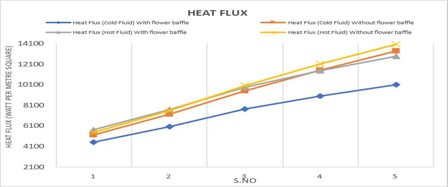
Fig. 4: Graph of heat flux in shell and tube heat exchanger.
International Research Journal of Engineering and Technology (IRJET) e-ISSN: 2395-0056 p-ISSN: 2395-0072
Volume: 11 Issue: 03 | Mar 2024 www.irjet.net
3.2 Convective heat transfer coefficient in cold fluid.
As shown in the below fig. 5, the convective heat transfer coefficientforcoldfluidishigherforSTHXwithflowerbaffle andnanofluidin comparison withSTHX with nanofluid only. Theflowerbafflecreatesturbulenceincoldfluidcausingto increasetheconvectiveheattransfercoefficientofnanofluid.
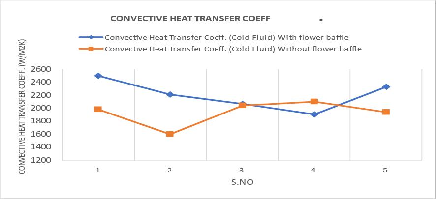
Fig. 5: Graph of Convective heat transfer coefficient in cold fluid.
3.3 Convective heat transfer coefficient in hot fluid.
Whereas, for hot fluid the convective heat transfer coefficient of hot fluid(water) for STHX with nanofluid is highincomparisonwithothercaseasshowninfig.6.
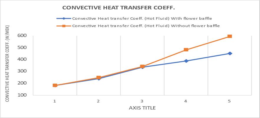
Fig. 6: Graph of Convective heat transfer coefficient in hot fluid
Thenanofluidgiveshigherheatfluxwiththeincreaseinthe differenceinmassflowrateofhotandcoldfluid,whereas the combine effect of flower baffle and nanofluid gives a higherconvectiveheattransfercoefficientforcoldfluid. Itisevidentthatinthecaseofflowerbafflewithnanofluid keepingtheflowrateof2lpmand10lpmoncoldandhot siderespectivelygivessatisfyingresultwithapressuredrop of4.75Paonthecoldside,andwithnanofluid2lpmand8 lpmoncoldandhotsiderespectivelygivessatisfyingresult withapressuredropof2.48Paintubeside. The combined effect of flower baffle and nanofluid SiO2 decreasesthepressuredroponthecoldsidewithaconstant mass flow rate, whereas in the case of the hot side the pressuredropsincreaseasthemassflowrateincreases. Above results indicates that with low-pressure drop-in tube sideSiO2nanofluidgiveshigherheatflux.
[1] P. Stehlik, J. Němčanský, D. Kral, L. Swanson, Comparison of correction factors for shell-and-tube heatexchangerswithsegmentalorhelicalbaffles,Heat TransferEng.15(1)(1994)55–65.
[2] Q. Wang, Q. Chen, G. Chen, M. Zeng, Numerical investigation on combined multiple shell-pass shelland-tube heat exchanger with continuous helical baffles, Int. J. Heat Mass Transfer 52 (5–6) (2009) 1214–1222.
[3] B.Gao,Q.Bi,Z.Nie,J.Wu,Experimentalstudyofeffects ofbafflehelixangleonshell-sideperformanceofshelland-tubeheatexchangerswithdiscontinuoushelical baffles,Exp.Therm.FluidSci.68(2015)48–57.
[4] S.ZeyninejadMovassag,F.NematiTaher,K.Razmi,R. TasoujiAzar,Tubebundlereplacementforsegmental and helical shell and tube heat exchangers: Performancecomparisonandfoulinginvestigationon theshellside,Appl.Therm.Eng.51(1)(2013)1162–1169.
[5] F.NematiTaher,S.ZeyninejadMovassag,K.Razmi,R. TasoujiAzar,Bafflespaceimpactontheperformance ofhelicalbaffleshellandtubeheatexchangers,Appl. Therm.Eng.44(2012)143–149.
[6] Y.You,A.Fan,S.Huang,W. Liu,Numerical modeling andexperimentalvalidationofheattransferandflow resistance on the shell side of a shell-and-tube heat exchanger with flower baffles, Int. J. Heat Mass Transfer55(25–26)(2012)7561–7569.
[7] Y.Wang,Z.Liu,S.Huang,W.Liu,W.Li,Experimental investigationofshell-and-tubeheatexchangerwitha newtypeofbaffles,HeatmassTransfer47(7)(2011) 833–839.
International Research Journal of Engineering and Technology (IRJET) e-ISSN: 2395-0056 p-ISSN: 2395-0072
Volume: 11 Issue: 03 | Mar 2024 www.irjet.net
[8] J.Lutcha,J.Nemcansky,Performanceimprovementof tubularheatexchangersbyhelicalbaffles,Chem.Eng. Res.Des.68(3)(1990)263–270.
[9] E. Ozden, I. Tari, Shell side CFD analysis of a small shell-and-tube heat exchanger, Energy Convers. Manage.51(5)(2011)1004–1014.
[10] Y.G.Lei,Y.L.He,P.Chu,R.Li,Designandoptimization ofheatexchangerswithhelicalbaffles,Chem.Eng.Sci. 63(17)(2008)4386–4395.
[11] J.F.Zhang,B.Li,W.J.Huang,Y.G.Lei,Y.L.He,W.Q.Tao, Experimental performance comparison of shell-side heattransferforshell-and-tubeheatexchangerswith middle-overlapped helical baffles and segmental baffles,Chem.Eng.Sci.64(8)(2009)1643–1653.
[12] B.Peng,Q.Wang,C.Zhang,G.Xie,L.Luo,Q.Chen,M. Zeng, An experimental study of shell-and-tube heat exchangers with continuous helical baffles, J. Heat Transfer129(10)(2007)1425–1431.
[13] G.Chen,Q.Wang,Experimentalandnumericalstudies ofshell-and-tubeheatexchangerswithhelicalbaffles, Paper presented at the ASME 2009 Heat Transfer SummerConferencecollocatedwiththeInterPACK09 and3rdEnergySustainabilityConferences,July19-23, 2009,SanFrancisco,California,USA,(2009).
[14] C.Wang, J.G.Zhu,Z.F.Sang, Experimental studieson thermal performance and flow resistance of heat exchangerswithhelicalbaffles,HeatTransferEng.30 (5)(2009)353–358.
[15] J.M.Gorman,K.R.Krautbauer,E.M.Sparrow,Thermal andfluidflowfirst-principlesnumericaldesignofan enhanced double pipe heat exchanger, Appl. Therm. Eng.107(2016)194–206.
[16] S.A.E. Sayed Ahmed, O.M. Mesalhy, M.A. Abdelatief, Flow and heat transfer enhancement in tube heat exchangers,HeatMassTransf.51(11)(2015)1607–1630.
[17] ElMaakoul,A.Laknizi,S.Saadeddine,A.BenAbdellah, M. Meziane, M. El Metoui, Numerical design and investigation of heat transfer enhancement and performance for an annulus with continuous helical baffles in a double-pipe heat exchanger, Energy Convers.Manage.133(2017)76–86.
[18] R.Amini,M.Amini,A.Jafarinia,M.Kashfi,Numerical investigation oneffects of usingsegmented and helical tubefinsonthermalperformanceandefficiencyofa shellandtubeheatexchanger,Appl.Therm.Eng.138 (2018)750–760.
[19] J.Liu,Z.C.Liu,W.Liu,3Dnumericalstudyonshellside heat transfer and flow characteristics of rod-baffle heatexchangerswithspirallycorrugatedtubes,Int.J. Therm.Sci.89(2015)34–42.
[20] Y. Chen, M. Fiebig, N.K. Mitra, Heat transfer enhancement of finned oval tubes with staggered punched longitudinal vortex generators, Int. J. Heat MassTransfer42(2000)417–435.
[21] T.A.Ibrahim,A.Gomaa,Thermalperformancecriteria ofelliptictubebundleincrossflow,Int.J.Therm.Sci. 45(11)(2009)2148–2158.
[22] A. Swain, M.K. Das, Convective heat transfer and pressuredropoverellipticalandflattenedtube,Heat Transfer AsianRes.45(5)(2016)462–481.
[23] ZhenbinHe,XiaomingFang,ZhengguoZhang,Xuenong Gao, Numerical investigation on performance comparisonofnon-Newtonianfluidflowinvertical heatexchangerscombinedhelicalbafflewithelliptic andcirculartubes,Appl.Therm.Eng.(2016), https://doi.org/10.1016/j.applthermaleng.2016.02.03 3.
[24] A.ShrikantAmbekar,R.Sivakumar,N.Anantharaman, M. Vivekenandan, CFD simulation study of shell and tube heat exchangers with different baffle segment configurations, Appl. Therm. Eng. 108 (2016) 999–1007.
[25] L. Huadong, V. Kottke, Effect of baffle spacing on pressuredropandlocalheattransferinshell-and-tube heatexchangersforstaggeredtubearrangement,Int.J. HeatMassTransfer41(1998)1303–1311.
[26] P. Stehlik, J. Nemcansky, D. Kral, L.W. Swanson, Comparison of correction factors for shell-and-tube heatexchangerswithsegmentalorhelicalbaffles,Heat TransferEng.15(1994)55–65.
[27] Y.S.Son,J.Y.Shin,Performanceofashell-and-tubeheat exchangerwithspiralbaffleplates,KSMEInt.J.15(11) (2001)1555–1562.
[28] D.Gaddis(Ed.), StandardsoftheTubularExchanger Manufacturers Association, TEMA Inc., Tarrytown (NY),2007.
[29] M. Elsaid, M. Ammar, A. Lashin, G. M. R. Assasa, Performance characteristics of shell and helically coiledtubeheatexchangerunderdifferenttubecrosssections, inclination angles and nanofluids, Case StudiesinThermalEngineering49(2023)103239.