
Volume: 11 Issue: 03 | Mar 2024 www.irjet.net
2395-0072

Volume: 11 Issue: 03 | Mar 2024 www.irjet.net
2395-0072
Dr. P. P. Tapkire1, Ms. Prajakta G. Pathak2, Mr. A. S. Chandanshive3
1 H.O.D.CivilDept.,N.B.NavaleSinhgadCollegeofEngineering,Solapur,Maharashtra,India-413255
2MasterOfTechnologyStudentin Civil Dept., N.B. Navale Sinhgad College of Engineering, Solapur, Maharashtra, India-413255
3Lecturer in Solapur Education Society’s Polytechnic Solapur, Maharashtra-413002
Abstract - Box girder bridges have emerged as a prominent choice in contemporary infrastructure projects due to their superior structural properties and versatility in construction. This paper explores the advantages and applications of box girders, highlighting their ability to resist torsion, accommodate heavier loads, and provide enhanced structural stiffness and strength compared to traditional I-beams. Economy and aesthetics play a significant role in the evolution of box girder designs, with features such as cantilevers and inclined webs enhancing both efficiency and visual appeal. Despite the complexity of analysis involving factors like flexure, shear, torsion, and distortion, box girder bridges remain a preferred choice for spans of up to 150 meters, demonstrating their effectiveness in meeting the demands of modern infrastructure development.
Key Words: IRCloadings,Boxgirderbridges,Rectangular boxgirder,Trapezoidalboxgirder,Torsionalresistance.
1.INTRODUCTION
Aboxortubular girderis agirderthat forms an enclosed tube with multiple walls, as opposed to anI-orH-beam Originally constructed ofrivetedwrought iron, they are now made of rolled or welded steel, aluminumextrusionsorprestressed concrete. Compared toanI-beam,theadvantageofaboxgirderisthatitbetter resiststorsion. Having multiple vertical webs, it can also carry more load than anI-beamof equal height (although itwillusemorematerialthanatallerI-beamofequivalent capacity) Box girder bridges are commonly used for highwayflyoversand for modern elevated structures oflight railtransport. Although the box girder bridge is normally a form ofbeam bridge, box girders may also be used oncable-stayedand other bridges. A box girder is formed when two web plates are joined by a common flangeatboththetopandbottom.Theclosedcellwhichis formedhasamuchgreatertorsionalstiffnessandstrength than an open section and it is this feature which is the usual reason for choosing a box girder configuration. The box girder consists of concrete, steel or a combination of both. Most modern elevated structures are built on the
basis of the box girder bridge. Anyeccentricloadwillcausehightorsionalstresseswhich will be counter acted by the box section. The analysis of such sections are more complicated due combination of flexure, shear, torsion, distortion. It is used for larger spanswithwidecross-section.Itcanbeusedforspansup to150mdependingupontheconstructionmethods.
This paper aims to find a suitable cross section for differentspantodepthratiowithvariousIRCLoading.
● Analysis and design of various sections of box girder forvariousIRCLoading.
● Different span to depth ratio for trapezoidal and rectangularsectionmustbeanalysesanddesign.
● Comparative charts are proposed to prepare for different span to depth ratio and for different cross section.
● Findingeffectofspantodepthratioondeformationof Trapezoidalandrectangularcrosssectiongirder
B. Paval [1] ThiswasaStudyofapre-stressedconcretebox girder bridge and to describe the linear, non-linear and time history analysis of this concrete spread box girder superstructure when subjected to different loads simulating the effect of traffic. The prestressed concrete boxgirderbridgesuperstructureanalysedinthebasecase consistsoftwoconcreteboxgirderswithsimplespan.The superstructure is loaded by IRC loads and the loads are incrementeduntilthebridgesuperstructuresystemfails.
Pragya Soni, Dr. P.S. Bokare [2] In this Paper The use of box-girders was proven to be a very efficient structural solution for highway bridges and flyovers due to its high tensional rigidity, serviceability, economy, aesthetics, and the ability to efficiently distribute the eccentric vehicular liveloadamongthewebsofthebox-girder.Forthemulti-
International Research Journal of Engineering and Technology (IRJET) e-ISSN:2395-0056
Volume: 11 Issue: 03 | Mar 2024 www.irjet.net p-ISSN:2395-0072
lane bridges, multi-spine/cell box-girders are most adoptedinordertolimitthelocaldeformationsinthetop slabofbox.Itwasfoundthatresearchershaveusedfinite element method for the analysis of box girder bridge. However, not many studies areavailable for thedesign of box Girder Bridge. Hence, this study emphasized on the designandanalysisofboxgirderstructure.Theliterature also indicates that the various researchers have used ANSYS, MIDAS and Staad-Pro for the analysis of PrestressedConcreteStructuresusingFEM.
Mr. Praveen Naik, Dr. R. Shreedhar [3] In the Thesistwo mostcommontypesofgirdersthatareusedinpracticeare beam and Box Girders was analysed. Though box girder designismorecomplicated,ithaswideacceptancedueto their structural efficiency, aesthetic appearance, better stability, and serviceability. Over years simple RCC box girders used for short spans resulted in long span prestressedconcretebridges.Theuseofpre-stressingenables concretebridgebeamstospanlongdistances.Boxgirders are constructed in single cell, double cell or multicell. Generally, bridge with a skew angle less than 20° is designed as normal bridge. If it is more than 20° there is changeinthebehaviouroftheskew bridge. Theobjective ofpresentstudyistocomparenormalandskewbridgeof box girder type, with parameter such as bending moments, shear forces & torsional moments for two span deck slabs by considering IRC class AA tracked loading. A simplysupportedtwospan,twolanePSCslabbridgedeck is considered in the present study. The different bridge spansconsideredare50m,60mand70mandskewangle is varied from 0° to 60° at 15°interval. The analysis has beencarriedoutusingSAP2000software.
Palden Humagai, Pavan Kumar Peddineni [4] In this Study they had worked on segmental pre-cast bridge structurememberthatwasmanufacturedinseveralshort units which during erection are joined together, end to end, and post- tensioned to form the completed superstructure.CantileverconcreteT-Beamgirderbridges composedofprecastreinforcedandpre-stressedconcrete beams with a T- cross section and a cast-in place topslab are frequently used for medium spans due to their competitiveness. The service behaviour of such bridges is verymuchinfluencedbytheirsegmentalconstruction,due to time-dependent materials behaviour that makes it difficult.
Vivek P. Joshi Ronak S. Gujjari [5] This paper was presented a literature review related to curved span PSC Box girder. The curvilinear nature of box girder bridges with their complex deformation patterns and stress fields have led designers adopt conservative methods for analysis & design. Recent literature on curved girder bridges to understand the complex behaviour. In the
present study an attempt has been made to study the SignificanceofPSCBoxGirders&Type,Curvatureeffectof span,liveloadeffect,wrappingstressincurvedBoxgirder, Shear Lag & Torsion effect due to curvature. Comparative study of analysis & design of PSC T-girder with PSC Box girder using software Staad - pro, ANSYS, MIDAS and CSI Bridge. Normal & Skew Box Girder with different geometricalcombinationshasbeenincluded.
Punil Kumar M P, Shilpa B. S. [6] This Paper was represented on Analysing the PSC Box girder bridge, statically and dynamically. Here with and without applicationofdynamicloads,theperformanceofbridgeis studied. The study of bridge with bearing between girder and top of pier are included. By applying moving load, vehicle (or) truck load, pre-stress and axial forces, the effects of bridge model are carefully studied. Determining the actual seismic demand of bridge depends on the behaviour of these models and the importance of bearing betweengirderandtopofpieristakenintoconsideration. Box girder bridges can have a considerable effect on the behaviour ofthe bridge especiallyintheshort to medium range of span such as 30m, 40m and 50m. In our project westudythebehaviourofboxgirderbridgeswithrespect to support reaction shear force, bending moment, torsion and axial force under standard IRC Class AA loading and the box girder bridges models analysed by finite element method.
A. Jayasri, V. Senthil Kumar [7] The author worked on studyofBridgesrangefromtimberdeckonstringersthat are supported at each end to very complex designs. Span lengths can vary from 6m (20 feet) to hundreds of meters(feet). The obstacle to be crossed may be a river, a road, railway, or a valley. Structural engineering work consists of designing new structures and repairing or rehabilitating existing ones. The bridge is a structure providing a passage overan obstaclemay be fora road, a railway and pipeline. This study is aimed to understand thebehaviourofGirderBridgewithtwolanesofdifferent span. ANSYS software is used as a tool for the analysis of performance including total deformation, bending moment,shearstressunderstaticanddynamicload.
Selvan V and Gopinath R.S [8] Author had worked on the continued enlargement of route network throughout the globe is basically the results of nice increasing traffic, population, and intensive growth of metropolitan urban areas. This growth has caused several changes within the use and development of assorted varieties of bridges. As Span will increase, dead load is an important increasing factor. To reduce the load, unnecessary material, which is not utilized to its full capacity, is removed out of section, thisendsupintheformofboxbeamorcellularstructures, depending upon whether the shear deformations may be
International Research Journal of Engineering and Technology (IRJET) e-ISSN:2395-0056
Volume: 11 Issue: 03 | Mar 2024 www.irjet.net p-ISSN:2395-0072
neglected or not. “When tension flanges of longitudinal girders area unit connected along, the resulting structure is called a box girder bridge.” In this work, a trial was created to comparative study the various shapes of PSC box beam Multi Cell Bridge exploitation CSI Bridge (V2017). Loading of IRC Class-A is applied and analysis is completedexploitationIRC112(2011).
J.S. Kalyan Rama [9] In this research work author had worked on “tension flanges of longitudinal girders which areconnectedresultsstructureasaboxgirderbridge.”An encompassing review of literature has been made regarding construction and a summary of general specifications with reference to IRC:18 have been discussed in chapter 3. Box girders can be universally applied from the point of view of load carrying, to their indifference as to whether the bending moments are positive or negative and to their torsional stiffness; from the point of view of economy. Analysis principles for torsion and distortion effects are applied to the section selected, and found satisfactory. Correspondingly, the problem has been analysed and designed for flexure and shear by giving due considerations for torsional and distortionaleffectsasaprecautionarymeasure.
Alyaa Shatti Mohan Alhamaidah [10] Inthisstudy,athree dimensionalstraightandhorizontallycurvedpre-stressed box section had been analysed with shell elements using the finite element analysis program ANSYS to examine structural behaviour and load carrying capacity. The box girderunderstaticgravity,pre-stressedandgravity+prestressed loading has been analysed. The model which has been investigated in this report is taken from a published paper and expanded to study the effects of curvature under different loads applied (UDLs). The report concludes that the FEA using shell elements can predict the behaviour of box girders with adequate accuracy through the comparisons made between stress results from analytical hand calculations and published work, both for the straight and curved box girder bridges. Furthertheoreticalandanalyticalinvestigationshavebeen carried out to study the effects of parameters such as horizontal curvature, pre-stressing, and traffic patterning. Forthispurpose,anewmodelwascreated,modelledwith an accurate pre-stress representation, and analysed as a three-dimensionalmodelusingtheANSYS.
Sandeep Kumar Ahirwar (2014) [11] the author had presented the various methods to understand the behaviour of Box Girder Bridges. Analysis of this paper indicates need to understand behaviour of box girder bridges with the help of various analytical methods to understandthebehaviouralaspect.
K, Chethan V R, Ashwini B TPG Student [12] The authors have worked on analysis of box girder bridges under IRC loading.TheirdiscussionwasontheAnalysisofBoxgirder bridges under IRC loading of two different types Single1cell and Multi cell with IRC standard codes followed superstructures subjected to load of heavy vehicles using CSi Bridge software 2015 version to know itsstructural behaviorandtodecidewhichstandardcode is better when comparing the results in determining the economicalsectioninallaspectsfortheassumedproblem Statement.Also,toknowaboutthemodelingpatternusing CSi bridge and to know the structural behaviour1considering the bridge object responses and horizontal moments of both single cell and multi cell box girdersunderIRCloadingcondition.
Rao Jang Sher1a, Muhammad Irfan-ul-Hassan1b, Muhammad Tal. Ghafoor1c, Atif [13] the authors had discussed analysis and design of box and T beam girder has been performed using SAP2000 in order to find out themostsuitabletypeof bridgesuperstructure.Themain objective of this study is to compare the structural behavior; optimization of materials used in each componentandcostcomparisonofboxandTbeamGirder Bridge. Previous research in this regard is based upon working stress method but this research follows limit statedesign.Detailedcomparisonshowsthatboxgirderis more suitable as compared to T beam girder even for shorter span in terms of structural stability and cost efficiency.
Gokul Mohandas V. Dr. P. Eswaramoorthi [14] Analysisof Prestressed concrete girder for bridge. The authors had Analysed BOX girder for un-factored Gravity loads and movingvehicularloadsasperIRC:6-2014andasperIRC: 18-2000. The work discusses about the modeling and analysis pattern of prestressed concrete bridges for different tendon profiles in MIDAS CIVIL software. The curved profile gives reduction in stress level and deflectioncomparedtostraighttendonprofile.
K. Hemalatha, Chippymol James, L. Natrayan, V. [15] the author decided main objective of this paper is to check whether both the T and box girder bridges have adopted for the assumed data with different Span conditions. The presentstudy,atwo-lanesimplysupportedRCCTeebeam girder and prestressed concrete box girder bridge analyzed and designed for dead load and IRC moving loads,wheretheconsideredmovingloadisofthetracked vehicleofclassA-Aloading.Courbon’smethodadoptedfor analysisanddesigning
Research
Volume: 11 Issue: 03 | Mar 2024 www.irjet.net p-ISSN:2395-0072
3.1 General
Structural engineering is closely connected in analysis of civil engineering structures, often analysis can be performed independently with accurate result. A comparative analysis is performed to get best cross sectionofbridgegirder.Inpreviouschapterwehaveseen about the theoretical formulation of box girder and loadingconditionsandflowandmethodologyisdiscussed incurrentchapter.
3.2 Flow of Research Work:
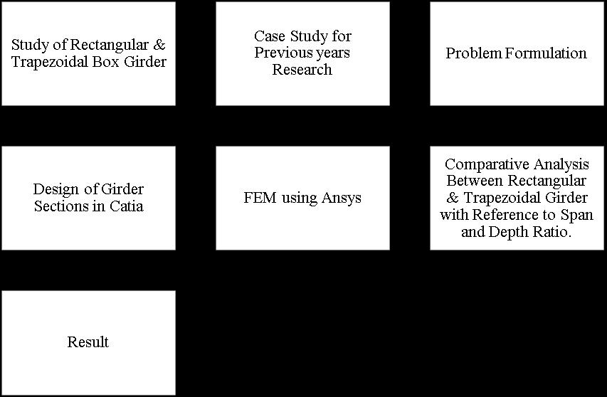
3.3 Methodology
The concrete slab is bonded to the bridge deck. A CAM layer is used to join the concrete slab and precast base track. The transverse movement of the precast concrete slab is restricted by the lateral stopper. The concrete slab and the base slab are separated between adjacent girders at the girder end. As a result, the continuous rail fastener systemistheonlything keeping the neighbouringgirders in place. The deck of the bridge is supported on the Butment and pier using a fixed bearing modelled as a spring element, whose stiffness has been mentioned in Table3.1. Also, the rail fastener system is modeled as a non-linearspringelementwithadiscretespacingof0.6m.
Ateverypoint,twofastenerswereattachedtotheleftand rightsidesofthebottomfaceoftherailtoprovidestability and restrict the transverse movement of the rails. The length of the spring element is taken as the thickness equal to that of a rail pad, which is generally 0.085 m. Tables 3.3 and 3.4 show the relationships between the differentpartsofthemodelandthesizeoftheirmesh.The selection of a reasonable size for various components based on mesh convergence is required for reliable outcomes.Theoptimumfinermeshwasadopted.
TypeofBridge Superstructure Rectangular Box GirderBridge Trapezoidal Box Girder Bridge
Crosssection BoxGirder Multicelledboxgirder
Carriageway
Width 7.5m
Kerbs 600mmoneachside
FootPaths 1.25mwideoneachside
Thicknessof wearingcoat 80mm
Laneofbridge Twolane
Longitudinal Girders 4 main girders at2.5 m interval
Spacingofcross Girders 5m
Celldimensions 2mwideby1.8mdeep
TH.ofTop bottomSlab 250mm&300mm 300mm
OverhangTh. 180mm 180mm
Thicknessof Web 200mm 300mm
Span
30,40,50,60m
Gradeof Concrete M40
Material PrestressedConcrete
LossRatio 0.8
TypeoftendonsHightensilestrandsof15.2mmdia.Confirmingto IRC:6006-2000.
Anchorages
Type 27K-15Freyssinettypeanchorages.
Typeof Supplementary r/f Fe-415HYSDbars
Loading Considered Dead load, wind & Prestress, Class 70R-Wheeled vehicle,andSeismic Forces
Designofbridge Deck
Class-1typeDesignofstructure conformingtothe codes IRC:6-2014,IRC:21- 2000, IS:1893-1987,IS: 875(Part-III)–1987
4.1 General
For multilane bridges box girders are the most adopted structural form. The parameters are varying which influences structural performance of box girders, the extensiveresearchsurveyindicatesvariousparametersas mentioned in the previous chapter. Considering various parameters flow of study also discussed in the previous chapter. Considering these various parameters two cross section of box girder i.e., Trapezoidal box girder and rectangular box girder is finalized for study. The combination of span to depth ratio and IRC loadings for different spans are analysed using the Finite Element Method and the cases and results obtained are discussed inthesubsequencesection.
5.2
Fromtheliteraturereviewvariousparametersinfluencing box girder performance are identified and combine effect oftheseparameterisselectedasatask,withthisobjective rectangularandtrapezoidalcrosssectionofboxgirderfor span30m,40m,50m&60mforloadingclassAA&classA variation of actual deflection in comparison with
permissiblevalueareplottedandobservationarenotedin previoussectionalsovariationinshearstressesisstudied and observation are worked out. Based on observations mentioned in previous subsection conclusions are drawn which are mentioned in subsequent chapters. The cases obtained from combination of above parameters are studied,andforcomparisonfollowingtermsaredefined.
● VariousSpanandvaryingdepthofgirder.
● Study of maximum shear stress for Class A and Class AAloading.
● StudyofDeflectionforClassA&ClassAAloading.
4.3 Effect of span to depth ratio on deformation for rectangular and trapezoidal box girder
Asdiscussedinprevioussectionvariouscasesarestudied for considering wearing span and Debt the cross section are analysed using finite element package maximum deformationareworkedforeachsection.Thevariationsof deformation are plotted for considering class a loading and class AA loading for different spans Variations are plotted considering 2D parameters. The ratio of actual deformation to permissible formation is calculated and various S/D are considered to differentiate changes that occur
4.3.1. Variation of deformation for class A and class AA loading for 30m span
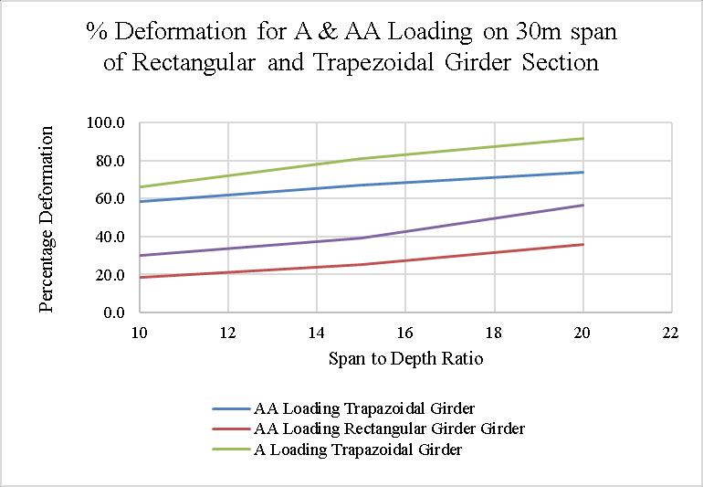
G1- Percentage Deformation for A & AA Loading on 30m span of Rectangular and Trapezoidal Girder Section
Observations:
Fromtheabovegraphfollowingpointsarenoted.
As span to depth ratio increases deformation also increases
International Research Journal of Engineering and Technology (IRJET) e-ISSN:2395-0056
Volume: 11 Issue: 03 | Mar 2024 www.irjet.net p-ISSN:2395-0072
The deformation ratio for class AA loading is on higher sideascomparedtoclassAloadingforconsideringC/S.
Rectangular C/S shows lower deformation compared to trapezoidal C/S for all span to depth ratio considered in section.
Almost20%deformationratioincreasesforspantodepth ratio of rectangular C/S from 10 to 20. There are slightly higher values after 15 span to depth ratio in both type of loading.
For trapezoidal C/S linear variation is observed for AA loading and deformations slightly increases after 15 span todepthratio
4.3.2 Variation of deformation for class A and class AA loading for 40m span.
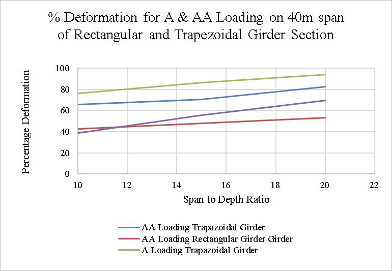
G2- Percentage Deformation for A & AA Loading on 40m span of Rectangular and Trapezoidal Girder Section
Observations:
Fromtheabovegraphsfollowingpointsarenoted.
1. Asspenttodepthratioincreasesdeformationalso increases
2. The deformation ratio for class AA loading is on lowersideascomparedtoclassAloadingforconsidering C/S
3. Rectangular C/S shows lower deformation compared to trapezoidal C/S for all span to depth ratio consideredinsection
4. DeformationpercentageofrectangulargirderinA loading is almost increased by 10% as compared with AA loading, also 10% lower than A loading of trapezoidal girder.
5. It seems that almost 20% difference of deformation percentage in trapezoidal girder section and rectangulargirdersection
4.3.3 Variation of deformation for class A and class AA loading for 50m span.
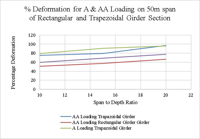
G3- Percentage Deformation for A & AA Loading on 50m span of Rectangular and Trapezoidal Girder Section.
Observations:
Fromtheabovegraphfollowingpointsarenoted.
1. Asspenttodepthratioincreasesdeformationalso increases
2. The formation ratioforclassAAloadingis on the lowersideascomparedtoclassAloadingforconsidering C/S,especiallyrectangulargirderC/S.
3. Rectangular C/S shows lower deformation compared to trapezoidal C/S for all span to depth ratio consideredinsection
4. Inthetrapezoidalsectionforlowerspantodepth ratio difference of % has been recorded in A loading and AA loading. For mid snap to depth ratio around % of differencehasbeenrecorded.
5. As we go for higher span to depth ratio the deformation percentages between trapezoidal section A loadingandAAloadingrecordedalmostthesame
6. For rectangular C/S the difference variation of deformation is observed almost the same for AA loading andAloadingforallspantodepthratio.
International Research Journal of Engineering and Technology (IRJET) e-ISSN:2395-0056
Volume: 11 Issue: 03 | Mar 2024 www.irjet.net p-ISSN:2395-0072
4.3.4 Variation of deformation for class A and class AA loading for 60m span
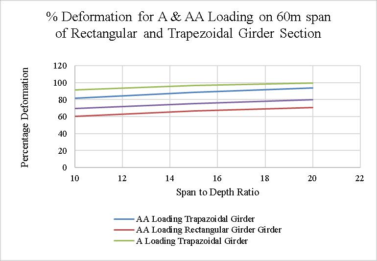
G4- Percentage Deformation for A & AA Loading on 60m span of Rectangular and Trapezoidal Girder Section
Observations:
Fromtheabovegraphfollowingpointsarenoted.
As spent to depth ratio increases deformation also increases
TheformationratioforclassAAloadingisonlowersideas comparedtoclassAloadingforconsideringC/S
Rectangular C/S shows lower deformation compared to trapezoidal C/S for all span to depth ratio considered in section
For this span the trapezoidal section reaches its deformation limit for A class loading specified by IRC in higherspantodepthratio
Effect of span to depth ratio on deformation for rectangularandtrapezoidalboxgirder
1. From the variation of different loading it is concluded thatdeformation due toloading A ison a higher side that ofloadingAA.
2. As the span to depth ratio increases the deformation percentagealsoincreases.
3.Forspantodepthratio10forallspansthedeformation percentage values are ranging from 40% to 80% for both the cross sections, except 30m span which shows deformation percentagevaluesrangingfrom 20% to 70% forallclassesofloadings.
4.For40m,thepercentagedeformationintherectangular girder is likely the same for the 10 and 15 span to depth ratio for class A and class AA loading. And then the deformation ratio in the loading rectangular cross section increased.
5.For50mspan,the percentagedeformationintriazolide girderislikelythesamefor10and20spantodepthratio forclassAandclassAAloading.Andthenthedeformation ratioinAloadingforthesameincreased.
6. For a 60m span, the percentage deformation increases graduallyforboththeclassloading.
7. From the discussion of results, it is concluded that the percentagedeformationintherectangularcrosssectionis approximately20%lessthanthatofthetrapezoidalcross section for all typesofloadingas well asall types of span todepthratio.
[1] Hassan A. Saab (1990), “Non-linear finite element analysis of steel frames in fire conditions”, University of Sheffield.
[2] Elsayed Mashaly, Mohamed El-Heweity *, Hamdy Abou-Elfath, Mohamed Osman (2010), “Finite element analysis of beam-to-column joints in steel frames under cyclicloading”,AlexandriaEngineeringJournal.
[3] R.A. Hawileh, A. Rahman, H. Tabatabai (2009), “Nonlinear finite element analysis and modeling of a precast hybrid”, University of Wisconsin-Milwaukee, AppliedMathematicalModelling34(2010)2562–2583.
[4] M. R. Mohamadi-Shoore, H. Ghafari, M. Amankhani (2013), “Finite Element Modeling of RHS Splice Beam Bolted Connections”, Indian Journal of Science and Technology.
[5] Mr. Vishawadeep Shivaji Ghodajkar, Dr. R.M. Sawant (2018),“FEMAnalysisofSteelBeamColumnJointbyusing Cantilever Weight and Acceleration”, Journal of Ceramics andConcreteSciencesVolume3Issue3.
[6] Kuldeep Kaushik, Avadesh K. Sharma, Rishi Kumar (2013), “A Review on Finite Element Analysis of Beam to Column Endplate Bolted Connection.”, IOSR Journal of Mechanical and Civil Engineering (IOSR-JMCE) e-ISSN: 2278-1684,p-ISSN: 2320-334X, Volume 8, Issue 1 (Jul.Aug.2013),PP97-103.
[7] Mr. Chintamani N. Khadake, Dr. Prashant M.Pawar (2020), “Finite element analysis of beam column joint in reinforced concrete structure.” International Research
International Research Journal of Engineering and Technology (IRJET) e-ISSN:2395-0056
Volume: 11 Issue: 03 | Mar 2024 www.irjet.net p-ISSN:2395-0072
Journal of Engineering and Technology (IRJET) e-ISSN: 2395-0056Volume:07Issue:07|July2020.
[8] Kathirvel Murugan K R V, Satheshkumar K. (2016), “ANALYTICAL & EXPERIMENTAL STUDY ON STRUCTURAL STEEL CONNECTIONS USING COMPONENT BASEDFINITEELEMENTMODEL”,InternationalJournalof Engineering Science Invention Research & Development; Vol.IIIssueXIMay2016.
[9] Balamuralikrishnan R., Saravanan J. (2019), “Finite elementanalysisofBeam – Columnjointsreinforced with GFRP reinforcements.”, Civil Engineering Journal Vol. 5, No.12,December,2019.
© 2024, IRJET | Impact Factor value: 8.226 | ISO 9001:2008
| Page436