
International Research Journal of Engineering and Technology (IRJET) e-ISSN:2395-0056
Volume: 11 Issue: 03 | Mar 2024 www.irjet.net p-ISSN:2395-0072


International Research Journal of Engineering and Technology (IRJET) e-ISSN:2395-0056
Volume: 11 Issue: 03 | Mar 2024 www.irjet.net p-ISSN:2395-0072
Phani Ram Gollapudi 1, Satish Kumar Brahmalla 2
1 Lead Bridge Engineer, Ramboll Engineers
2 Assistant Professor, Department of Civil Engineering, Jayamukhi Institute of Technological Science
Abstract: Thebridgesuperstructureflyover builtonNational Highwayroute16 (NH-16)nearBenzcirclein Vijayawada to act as grade separated highway for vehicles to cross over National Highway route 65 (NH-65) is made of precast and posttensioned concrete girders. The first part of this two-part publication discussed the analysis of the concrete bridge girders subjectedtovehicularloadsconsideredasperIndianRoadsCongressSpecifications.The designbendingmomentsandshear forcesforthegirdersandslabarecomputedusinggrillageanalysismodel.Thecurrentarticle,whichisthesecondpartofthis studydetailsthesuperstructuregirderdesignofpost-tensionedmembers precastattheconcreteplant. Thegirdersaretwostagepost-tensionedatprecastyardandtransportedto thesiteforerectiononpiers.Thepost-tensioningdesignanddetails are presented in this paper along with sectional geometry and reinforcement detailing sketches for the girders and the diaphragms. The reinforcement schedule is presented. Finally the bridge superstructure is rated for sustainability and resiliencyscorebasedonthedesignandconstructionpracticesfollowedduringtheengineeringofthisbridge.
Keywords: Design,Post-tensioning,Sustainability,Resilience,Bridge,Concrete
1. Introduction
The bridge on NH-16 near Benz Circle in the city of Vijayawada is built as two separate carriageways each of 3-lane posttensionedconcretegirderbridgestocrossovertheat-gradevehiculartrafficonNH-65.Thebridgehasatotalcarriagewayof 11.5mcurbtocurb Thetotaldeckwidthincludingcrashbarriersatbothendsis 12.5m Thedeckissupportedbyfour posttensioned concrete girders spaced at 3.1 m on center and supporting an overhanging slab of 1.6m cantilevered on the edge girders.Thefourbridgegirdersareconnectedbythreecrossdiaphragmsoneateachsupportlocationandoneatthemidspan. The concrete girders along with cross diaphragms are supported on elastomer bearing pads installed on top of reinforced concrete pedestals cast monolithic with pier caps. The girders are rectangular at support locations and taper to become Ishapedalongtherestoftheirlength.Thefirstpartofthistwo-phasearticlefocusedontheanalysismethodsanddetailsofthe bridge superstructure [1] The bridge girders and slab system were analyzed as a grillage system in Staad Pro software. The maximum bending moments and shear forces were determined after considering Indian Roads Congress [2, 3, 4, 5, 6] vehicularloadeffects.Thesummaryofdesignforcesonthegirderandslabsystemwasprovidedattheendofthefirstphase article.BoththeanalysesanddesignofthesebridgeelementshavebeenperformedinaccordancewithIRCcodespecifications andrecommendations[7,8] TheseismicdesignhasbeenperformedinaccordancewithIS1893[9,10]
The current article, which is the second phase of this study details the girder designs for this bridge superstructure. The girdersaredesignedaspost-tensionedconcretemembers.Thegirdersareprecastattheplantandthenpost-tensionedbyfour cablesinmulti-stagepost-tensioningoperations.Thegirdersarepost-tensionedwhenthegirderconcretereachesthespecific characteristic strength or specified age whichever is later. The girders are shipped to the site after the two-stage posttensioning is completed. This article provides the details of the post-tensioning such as jacking forces, number of cables, the strandtype,sizeandnumberofstrands,thehorizontalandverticalprofileofthecablesalongwithanyotherdetailspertaining to post-tensioning of the cables. The article also provides the drawings showing the prestressing forces, cable profiles and anchor zone details. The article also provides the main reinforcement and shear reinforcement detailing followed in the girders to ensure composite beam action when tied with the cast-in-place deck slab reinforcement. Finally, the author discussestheengineeringandconstructionpracticesfollowedinthedesignandconstructionofthisbridgesuperstructureand assign a sustainability score to the bridge which is an indicator of the impact of the bridge construction on environmental sustainabilityanditsresiliencetomajorweatherrelateddisastersandaccidentalforcesthatexceeddesignbasisloads.

International Research Journal of Engineering and Technology (IRJET) e-ISSN:2395-0056
Volume: 11 Issue: 03 | Mar 2024 www.irjet.net p-ISSN:2395-0072
The girders are designed for vehicular forces including gravity, centrifugal and braking forces in addition to the self weight loads,imposeddeadloadsandthewearingcoatonthebridgedeck [11].Theanalysisofthebridgegirdersisperformedusing linear member analysis using STAAD structural analysis software In this analysis the beam members are discretized as longitudinal 1D or line members [12] whereas the slab is discretized as transverse line members to form a grillage of finite elementmeshmembers.Theresultsoftheanalyseswerepublishedinthefirstphaseofthisstudy.Thissecondphasepresents thepost-tensioningdetailsoftheprestressingofthegirders.
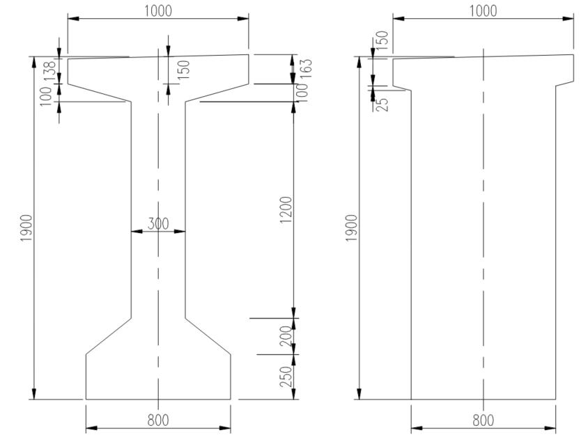
TheprecastbeamsaredesignedasI-girderswithanoveralldepthof1.9m Thisdepthappearstobeslightlyoverconservative because the typical span-to-depth ratios for prestressed girders is in the range of 20-25, this means a girder depth of 1.5m wouldbesufficientforthis span Howeveranextra400mmdepth isnotoverlyconservative. Thegirdersarerectangularin geometryatthesupportsectionandtransitiontoanI-girdertowardsthemidspan.Thewebsofthegirdersare300mmthick, andthebottomflangeismade800mmwidewithatopflangeofaboutameterwide.Thedepthofthetopflangevariesfrom about250 mmat theface ofthe web toabout 150 mm atthe end of the flange. Figure 1showsthe geometry oftheprecast girder at the support section where the webs are wider (800mm) and rectangular while at other sections away from the supportwherethegirderisI-shaped.ThegirdersandthedecksslabaremadeofconcretegradeM45.Forreinforcementsteel gradeof500MPaisused.
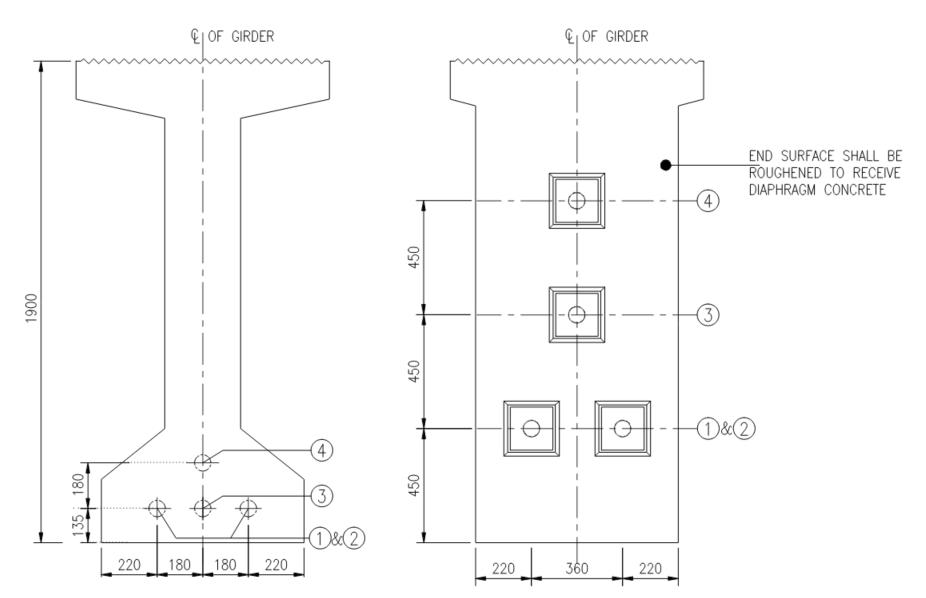
Thegirdersinthisbridgearedesignedasprestressedconcretemembers.Themembersareposttensionedintheprecastyard. Eachgirderhas4prestressingcablesintotal.Outofthe4cables,3cableshaveabout19strandsbundledtogetherwhereas the 4th cableismadeof12strands.However,inallcables,oneofthestrandsisnotstressedbecauseitisaddedanextrajustincase any of the strands snap or need to be removed if they do not meet required ductility. Also, the inner girders have lesser numberofstrandsascomparedtooutergirdersbecausetheloaddemandsonthe outergirdersishigherthaninnergirders. Thestrandsare12.7mmindiameterandhaveanareaof98.7sqmm. Thestrandshaveaminimumultimatestrengthof1860 MPa.Thestrandsaretensionedtoajackingforceofabout70%oftheultimatestrengthofthestrand. Thefrictioncoefficient istakenas0.17whereasthewobblecoefficientistakenas0.002permeterofgirderlength.

International Research Journal of Engineering and Technology (IRJET) e-ISSN:2395-0056
Volume: 11 Issue: 03 | Mar 2024 www.irjet.net p-ISSN:2395-0072

2024, IRJET | Impact Factor value: 8.226 | ISO 9001:2008 Certified Journal | Page213 ; At Midspan(L), At Support (R)
3: Profile Details of Post-Tensioning Cables

International Research Journal of Engineering and Technology (IRJET) e-ISSN:2395-0056
Volume: 11 Issue: 03 | Mar 2024 www.irjet.net p-ISSN:2395-0072
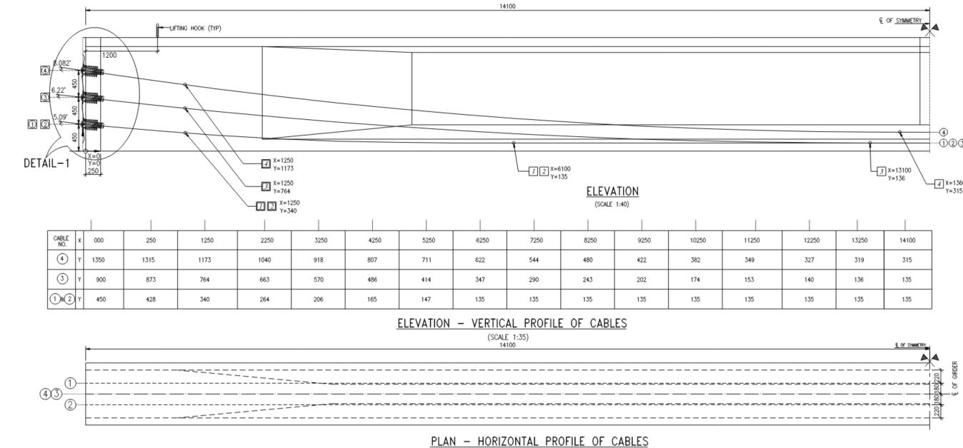
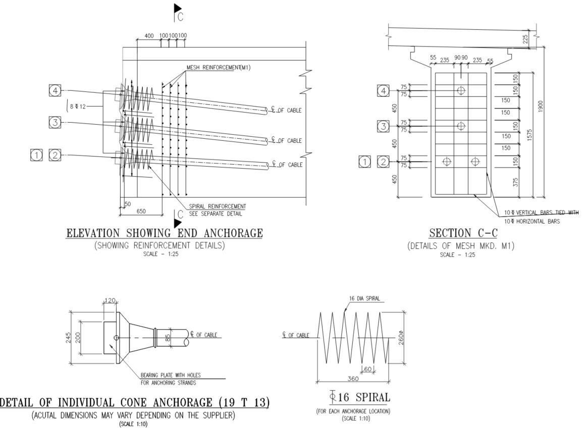
Figures 2 and 3 show the layout of the post-tensioned cables and the details of the strands. The figures also present the vertical and horizontal profileof the cablesalong the lengthofthegirders. Thecablesfollow a parabolicprofile whichis the most preferred profile to match the bending moment profile of beams. The coordinates of the cable along the length of the girder are tabulated for each of the cables. Looking at Figure 3, it can be found that vertical profile of cable 3 blends with cables1and2atabout13.1mfromthesupport. Theposttensioningforceisappliedintwostages.Inthefirststage, cables3 and4arestressedonthe7thdayafterthegirdersarecastandhavereachedaminimumstrengthof30MPa.Thisstrengthis required so the girders can be taken off the precast bed and they are self-sufficient to carry their self weight, lifting and handlingofthegirderswithintheyard[13]. Thecables3and4arestressedaftertheconcretereachesanageof28daysand hasaminimumstrengthof45MPa. Thedetailsofanchoragezonereinforcementintheformofsteelspiralties arepresented in Figure 4. The spirals are 16mm dia bars with a pitch of 60mm for about 360mm length along the anchorage region. The detailsofthe19tonanchorageconearealsoshowninthesamefigure.Theslipofthestrandatanchorconeislimitedto6mm fordesignpurposes.

International Research Journal of Engineering and Technology (IRJET) e-ISSN:2395-0056
Volume: 11 Issue: 03 | Mar 2024 www.irjet.net p-ISSN:2395-0072
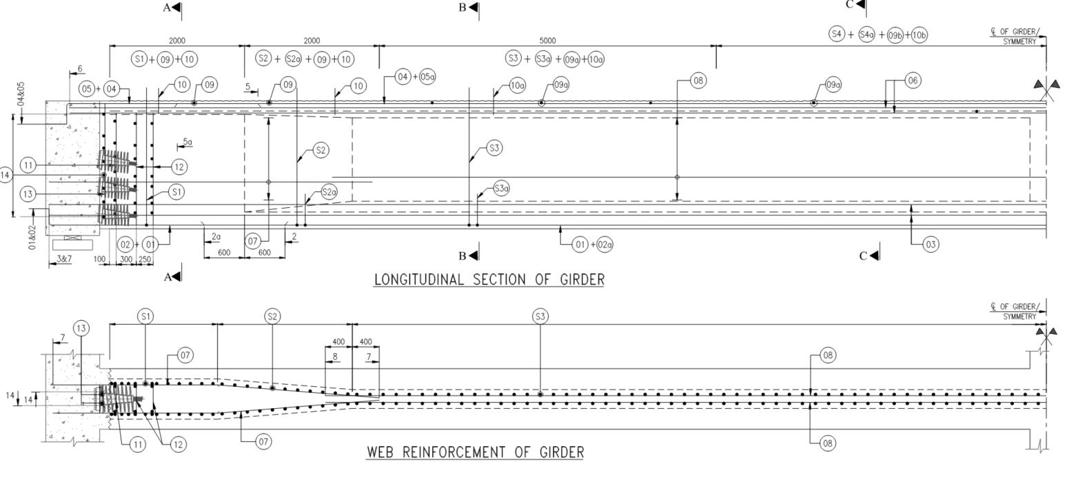
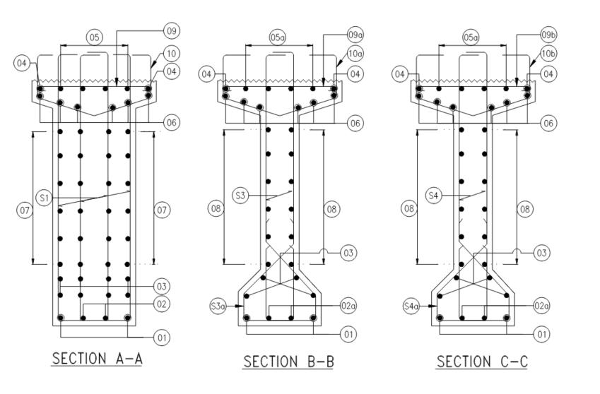
The post-tensioned girders still need to be reinforced with steel bars for multiple reasons such as side face reinforcement requirements, local shear force effects in the girder stems, for ductile failure and for the shear reinforcement across the interface with slab. Figure 5 shows the side face reinforcement and shear reinforcement distribution in the girder along its length.Whilebarsofsize10mmareusedassidefacereinforcementalongthedepthofthegirder(though16mmbarsusedat endsections),12mmsizeshearstirrupsareusedingeneralatabout150mmspacingforshearstrengtheningofthegirder. In total 4leggedsheartiesare usedasinterfaceshearreinforcementatsupport whereas 2-leggedstirrupsareusedatsections awayfromsupports.Thegirdershave4barsof16mmsizeattheirbottomlayer.Thesesheardetailsforthegirdersareshown inFigure6.

International Research Journal of Engineering and Technology (IRJET) e-ISSN:2395-0056
Volume: 11 Issue: 03 | Mar 2024 www.irjet.net p-ISSN:2395-0072
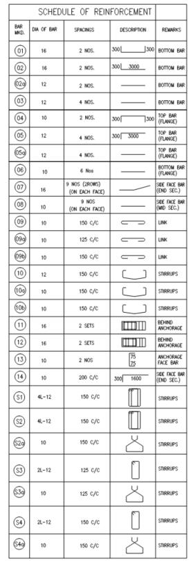
Figure7showsthescheduleofreinforcementtobereferredtotounderstandthereinforcementdetailsprovidedinthegirder and slab. The diameter, spacing and the length of the steel bars shown in the schedule are in mm. This figure 7 should be referredtowhilereadingthereinforcementdetailsshowninFigures5and6.

International Research Journal of Engineering and Technology (IRJET) e-ISSN:2395-0056
Volume: 11 Issue: 03 | Mar 2024 www.irjet.net p-ISSN:2395-0072 © 2024, IRJET | Impact Factor value: 8.226 | ISO 9001:2008 Certified Journal | Page217


: Diaphragm Reinforcement Details; End (L), Intermediate (R)
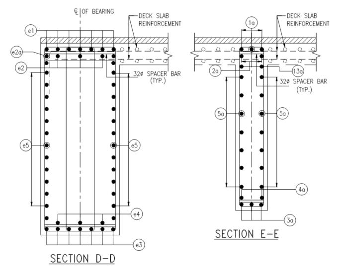
9 : Diaphragm Reinforcement Sections; End (L), Intermediate (R)

International Research Journal of Engineering and Technology (IRJET) e-ISSN:2395-0056
Volume: 11 Issue: 03 | Mar 2024 www.irjet.net p-ISSN:2395-0072
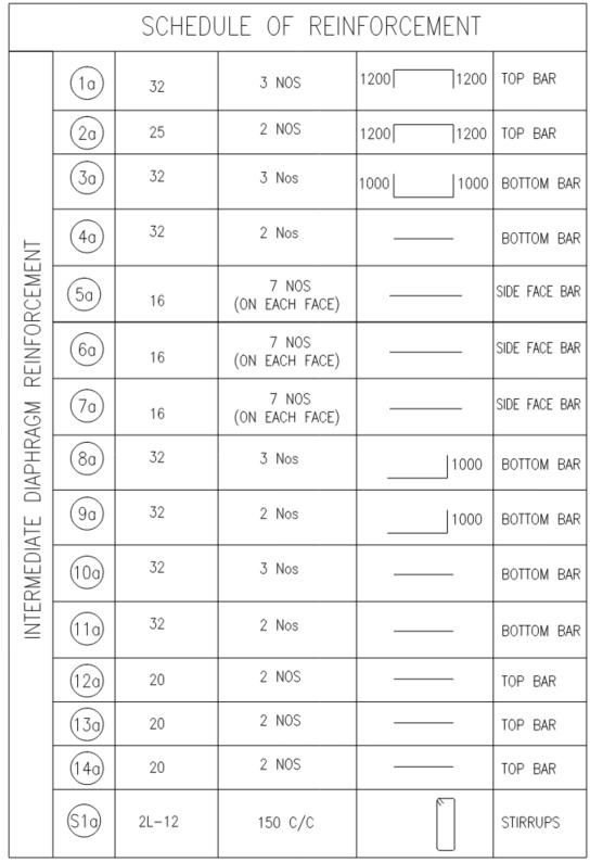
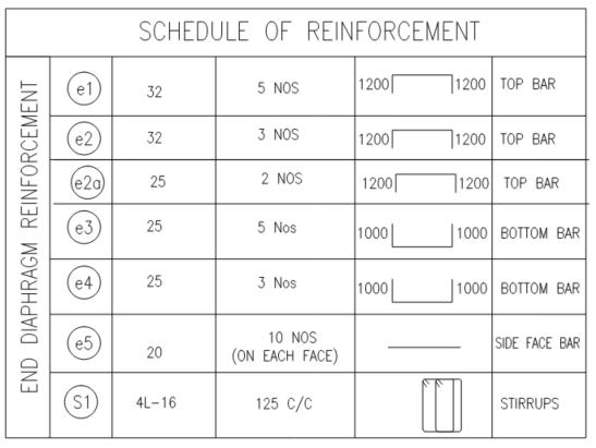
Thebridgehasthreediaphragmsconnectingthe4girdersacrossandimprovingthestiffnessandstructuralrobustnessofthe system for better distribution of forces to each of the girders as well as to slab both directions. Two of the diaphragms are locatedatsupportlocations,oneateachsupport.Thethirddiaphragmisthinnerwith300mmthickribatthemidspanofthe superstructure connecting the 4 girders at midspan. Figure 8 shows the reinforcement details of the diaphragms at support location and at midspan location. The main reinforcement in the diaphragms consists of 32mm and 25mm bars and runs paralleltothediaphragmlength.Thesidefacereinforcementinthesediaphragmsisarrangedusing10barsof20mmsizeas thesediaphragmbeamsaredeeperthanthethresholdforsidefacereinforcement.Theshearreinforcementismadeof16mm barswith4leggedfullyenclosedstirrups. Figure 9showssectionaldetailsofreinforcementinthesediaphragms. Theshear stirrupsenclosethedeckslabformonolithicactionofthediaphragmswithdeckslab.Whiletheenddiaphragmshave4legged shearstirrups,theintermediatediaphragmisonly300mmthick,so2leggedstirrupsareused forthismember.Theshearties ininteriordiaphragmarespacedat150mmoncenter whereastheyareat125mmoncenterintheenddiaphragms.Tofully understand the reinforcement scheme inside these diaphragm members, the readers may refer to the schedule of reinforcementoutlinedinFigure10.
From the review of the engineering and construction process of the bridge superstructure members and the deck, it can be noted that some good sustainable practices have been implemented in the engineering and construction of this bridge Prestressing with post-tensioned girders not only contributes to high design efficiency, but also improves the durability of concrete significantly. Prestressed structural members are reported to have significantly higher resistance to cracking and spelling of concrete [14]. These members have higher corrosion resistance as compared to reinforced concrete members (RCC)byvirtueoftheirimproveddensitiesandlowerwaterpermeability.Prestressedgirdersshowmuchhigherstiffnessand thuslowerdeflectionsduringservicestageascomparedtoRCCgirders.Prestressedgirdersalsohavehighresiliencetoimpact loadsandvibrations[15].Assuchtheyareanexcellentfitforbridgestructureswheredynamicvehicularloadstransferheavy

International Research Journal of Engineering and Technology (IRJET) e-ISSN:2395-0056
Volume: 11 Issue: 03 | Mar 2024 www.irjet.net p-ISSN:2395-0072
impact forces to the girders. It is also reported that the deterioration and ageing of prestressed girder bridges are slower as compared to RCC girder bridges [16]. Also, the maintenance requirements as well the cost of maintenance treatments for prestressed girders are significantly lower than RCC girders owing to improved engineering properties of these members. Prestressing concrete members improves their resilience to extreme weather conditions triggered by climate change by avoiding complete failure of these members owing to their redundancy and resilience to short-term high intensity forces beyonddesignbasisforces[17].
Inadditiontopost-tensioning,theconstructionofthesebridgesadoptedafewmoregoodpractices.Thegirdersarefabricated and post-tensioned in the precast yard. Precast concrete offers many benefits such as greater quality control, efficiency in fabricationthatoffersspeedandeconomyinconstructionofmembers.Precastconcreteoffersthesolutionforfieldproblems such as onsite stacking, expensive formwork and traffic restrictions and inconvenience to road users. The girders for this bridge are fabricated in precast plant, post-tensioned in the yard and brought to site at the time of erection. This process is veryefficientand removed theproblemsassociatedwithtrafficrestrictions,onsitematerial stackingandlaborsupplyissues [18]. Precast combined with prestressing made this project construction achieve higher sustainability and resilience score comparedwithtraditionalbridgesbuiltinIndia
Anothergoodpracticeappliedintheconstructionofthisbridgeistheuseofsteeldeckingongirderstoaidthecastingof deck slab.Theuseofdeckslabsignificantlyremovestheneedforexpensiveformworkatsiteduringconcretepouringandcuringof slab [19]. Typically this is very laborious with huge formwork supported from at grade road under the bridge deck. The formwork is not only expensive but also time consuming and labor intensive. It causes great inconvenience to road traffic throughout the duration of its construction and until the completion of the bridge deck and till the bridge reaches 14 day strength. The use of steel decking completely removes the need for formwork support from under the bridge and thus enhancesthesustainabilityscoreofthebridge.
Though this bridge has a good sustainability score, there is still a good scope for improving its sustainability and resilience score.Theauthorlikestopointout afewmissedopportunitiesinfurtherenhancingthesustainabilityandresiliencescoreof thebridge.Onesuchopportunity wouldbetheuseofUltra-High-Performanceconcrete(UHPC)forbridge joints.UHPCjoints greatly enhance the durability of bridge joints and reduce maintenance costs [20]. UHPC joints are being used in the construction of longitudinal and transverse joints in bridges in advanced countries and show very good performance. By virtueofitshightensilestrength,lowwaterpermeability,greaterimpactresistanceandminimalspallingandcracking,UHPC offersexcellentapplicationstobridgejoints[21]becausejointsinbridgesaremostsusceptibletoimpactloadsandusuallyare the high maintenance elements of a bridge due to wear and tear from traffic and weather conditions. The overall structural systemwouldachieveaverygoodresiliencescoreaswellifthejointsonthebridgearecastwithUHPC.Thesehighstrength joints when combined with post-tensioned girders and solid diaphragms at support and end location [22] would make this superstructuresystemnotonlysustainableintermsofhighlifespan,lowmaintenance,lowlifecyclecostsandhighresilience to extreme weather events such as seismic, wind [23], flooding and hurricane forces the occurrence of whose has increased overthelastfewdecadesduetoclimatechangeontheplanet.
Thisisthesecondpartofthetwo-partstudyonthebridgesuperstructureonNH-16inIndia nearVijayawadacity.Whilethe firstpartdetailedthe analysesanddesignmethodsusedinthe engineering ofposttensionedsuperstructuregirdersfor this bridge,thissecondpartpresentsthepost-tensioningdetailsofthesuperstructuregirderalongwiththereinforcementinthese girders and cross diaphragms. The post-tensioning cable layout, quantity and number of strands and the sequence of prestressing are explained in detail. The vertical and horizontal profile of the cables along the girder length are shown. The supplemental reinforcement details of the girder such as side-face reinforcement, the girder shear reinforcement and the interfacesheartiesacrosstheslabinterfaceare presented.Finally,adetaileddiscussionispresentedaboutthesustainability practices implemented in the engineering and construction of the bridge superstructure and the authors acknowledge the goodpracticesfollowedalongwithrecommendationsforfurtherimprovementofnovelpracticestoenhancethesustainability and resilience of the bridge to natural forces stemming from intense weather events caused by global warming and climate changehappeningacrossourearth.

International Research Journal of Engineering and Technology (IRJET) e-ISSN:2395-0056
Volume: 11 Issue: 03 | Mar 2024 www.irjet.net p-ISSN:2395-0072
The authors would like to acknowledge the support of the office of National Highway Authority of India (NHAI), Ministry of Road Transport & Highways, Government of India for providing the drawings for the bridge superstructure. The authors acknowledgetheguidanceofDr.SrimaruthiJonnalagadda whoisaHonoraryProfessoratVRSiddharthaEngineeringCollege inVijayawada
References
[1.] Gollapudi, P.R., Dendukuri, S.C., & Brahmalla, S.C. (2024). The Bridge Through The College (Part-1): Conception and Construction of Reinforced Concrete Bridge Across College Campus, International Journal of Scientific Research in Engineering and Management, 8(1), 1-11
[2.] IRC 5. (2015). Standard Specifications And Code Of Practice For Road Bridges, Section: I General Features of Design (Eighth Revision), IndianRoadsCongress
[3.] IRC6.(2017). Standard Specifications And Code Of Practice For Road Bridges, Section: II Loads And Load Combinations (Seventh Revision), IndianRoadsCongress
[4.] IRC 22. (2015). Standard Specifications And Code Of Practice For Road Bridges, Section: VI Composite Construction (Limit States Design) (Third Revision), IndianRoadsCongress
[5.] IRC112.(2011).Code of Practice for Concrete Road Bridges, IndianRoadsCongress
[6.] IRCSP:114.(2018).Guidelines for Seismic Design of Road Bridges, IndianRoadsCongress
[7.] Kumar,T.P.,&Ram,G.P.(2015).AnalysisandDesignofSuperStructureofRoadCumRailwayBridgeAcrossKrishna River International Journal of Engineering & Science Research,5,830-838.
[8.] Raj,K.K.,&Phani,R.G.(2017).Designandstudyonbehaviorofskewslabbridgeswithvariousskewangles. Journal of Applied Science and Innovations, 1(2).
[9.] IS 1893. (2016). Criteria for Earthquake Resistant Design of Structures - Part 1 : General Provisions and Buildings, BureauofIndianStandards
[10.] IS1893.(2014). Criteria for Earthquake Resistant Design of Structures - Part 3: Bridges and Retaining Walls, Bureauof IndianStandards
[11.] Johnson,D.V.(2017). Essentials of bridge engineering.OxfordandIBHPublishing.
[12.] SitaramVemuri.,andSrimaruthiJonnalagadda.2023. AnalysesofBoxBridgeandComparisonofStructural Behavior using 3D Finite Element and Typical 1D Line Models. International Journal for Research in Applied Science & Engineering Technology, 11(8),488-497.
[13.] Ram,G.P.(2021).BackgroundofDoubleTeeConstructionandNeedforStandardizedPrecastDoubleTeeforIndian BuildingIndustry. Turkish Journal of Computer and Mathematics Education (TURCOMAT), 12(11),2978-2989.
[14.] Srimaruthi Jonnalagadda., and Sitaram Vemuri. 2023. Novel Methods and Materials for Concrete Floor Slab Construction for Small Family Housing Buildings in India. International Research Journal of Engineering and Technology, 10(7),1048-1056.
[15.] Vineeth, M. K., Kumari, T. G., & Ram, G. P. (2019). Design Concept of Pre-Stressed Balanced Cantilever Segmental Bridge. International Journal of Architectural Design and Management, 2(1),10-1

International Research Journal of Engineering and Technology (IRJET) e-ISSN:2395-0056
Volume: 11 Issue: 03 | Mar 2024 www.irjet.net p-ISSN:2395-0072 © 2024, IRJET | Impact Factor value: 8.226 | ISO 9001:2008 Certified Journal | Page221
[16.] Jonnalagadda, S. (2016). Artificial Neural Networks, Non Linear Auto Regression Networks (NARX) and Causal Loop Diagram Approaches for Modelling Bridge Infrastructure Conditions. All Dissertations, 1725. https://tigerprints.clemson.edu/all_dissertations/1725
[17.] Jonnalagadda,S.,Jonnalagadda,V.,& Jonnalagadda,N.(2024).AFramework forConstruction,Maintenance,Function and Policy Adaptations to Build Resilience to Infrastructure Against the Impacts of the Climate Change, European Modern Studies Journal, 7(6),185-193
[18.] PCIMNL133.(2014) Bridge Design Manual, MNL-133-14, 3rd Edition, Chicago,IL
[19.] Srimaruthi Jonnalagadda., and Sitaram Vemuri. 2023. “Challenges in Traditonal Concrete Slab Construction for HousingBuildingsinDevelopingCountriesandCriticalNeedforNovelMethods.” International Journal of Advances in Engineering and Management, 5(5),176-186.
[20.] Jonnalagadda, S., & Chava, S. (2023). Ultra-High-Performance Concrete (UHPC): A state-of-the-art review of material behavior,structuralapplicationsandfuture. Electronic Journal of Structural Engineering, 23(4),25-30.
[21.] Jonnalagadda, S., & Vemuri, S. (2023). Choosing Conventional Concrete, Ultra-High Performance Concrete or Steel as MaterialofConstruction:AnOpinion. European Modern Studies Journal, 7(4),280-288.
[22.] Kumari, T. G., Srilatha, N., Prasad, M. C., Ram, G. P., & Vineeth, M. K. (2022). A parametric study on the cost optimizationofareinforcedconcreteabutmentusingageneticalgorithm. Canadian Journal of Civil Engineering, 49(8), 1392-1401.
[23.] Sitaram Vemuri., and Srimaruthi Jonnalagadda. 2023. “Wind Analysis of Tall Buildings Using Codal Provisions, Stochastic Approach and CFD – A Comparative Study” . International Journal of Advances in Engineering and Management, 5(7),58-68.