
International Research Journal of Engineering and Technology (IRJET) e-ISSN: 2395-0056
Volume: 11 Issue: 03 | Mar 2024 www.irjet.net p-ISSN: 2395-0072

International Research Journal of Engineering and Technology (IRJET) e-ISSN: 2395-0056
Volume: 11 Issue: 03 | Mar 2024 www.irjet.net p-ISSN: 2395-0072
Muhammed Ishack V1 , Ahammed Adil P2 , Amal P K3 , Rohith V T4 Jibi R5
1234Graduate Student, 5Assistant Professor Department of Mechanical Engineering, AWH Engineering College Calicut, Kerala, India ***
Abstract – Infourthindustrialrevolutionautomationplay a vital role. Automation is the science of designing and building mechanism useful for real life applications. Automationhasbeendefinedastheuseofcontrolsystemsuch aspneumatics,hydraulics,electrical,electronicsandcomputer to control industrial machinery and process reducing use of human effort. Now adays more and more industrial application use pneumatic system instead of hydraulics and electromotive because of continuous availability of compressed air and they may operative in flammable conditionwithout ignitingor exploding.Pneumatic system is more applicable because of their simplicity, reliability and area of operations. This project work consists design simulationanddevelopmentofcascadepneumaticsequential circuit.
Key Words: Automation, Simulation, Hydraulic system, Pneumatic Sytem.
1.INTRODUCTION
Pneumaticisabranchofengineeringthatdealswithstudyof compressed air /inert gas and their use in engineering applications.ThewordpneumaticsderivedfromtheGreek pneumameaningbreathorair.Pneumaticsistheapplication of compressed or pressurized air to power machine to controlorregulatethem.Pneumaticsalsodefinedasbranch offluidpowerthatdealswithgeneration,transmissionand control of power using pressurized air. In a pneumatic system compressed air using as working fluid for power transmission.Anaircompressorconvertsmechanicalenergy of primover in to pressure energy of compressed air. Compressed air is used for desired work. Pneumatic cylinder,aircylinderaremechanicaldeviceswhichusethe power of compressed gas to produce a force in a reciprocating linear motion. Direction control valves are usedtocontroldirectionofactuationofpneumaticcylinder. Inindustrialapplicationpneumaticsarepreferredbecause they are quitter, cleaner and do not require large amount spaceforstoringasoperatingfluidisgas.
Inindustrialapplicationsimulationplayavitalroleinpreproduction. Effective pneumatic system requires effective workingsimulation.FluidSIMisasoftwaretoolforcreating simulatinghydraulic,pneumatic,electro-hydraulic,electropneumaticdigitalelectronicsystem.
Main aim of project work is design simulate and development of pneumatic cascade sequential circuit A+B+B-A-configuration. Pneumatic diagram describes the relation between each pneumatic components as per equipmentofpneumaticsystem.
1.DesignandFabricationofSequencingCircuitwith SingleDoubleActingCylinder.
Author:V.G.Vijaya
Aim of project work is construction of pneumatic device assemblyforpressfittingapintoahole.Forpress-fittinga pintoholeusingapneumaticdeviceaccomplishesacylinder andabuttontooperateit Inthisworkpneumaticcylinder actuatedsuchawaythatonlywhenbothpalmbutton3-way valvesareoperatednearlysimultaneously.Themainmotto ofworkistopressfitapintoholeusingpneumaticdevices by economically and to ensure the operator’s safety. Designedandfabricated“sequencingsingle,doubleacting cylinder”helpstoknowhowtoachievelow-costautomation.
2.DesignandDevelopmentofPneumaticPunchingMachine
Author:AnandKumarSingh,MiteshLPate
Hand operated punching has many advantages and disadvantages, like hand punching has accuracy and job availabilitybutduetolateworkcomplete,accidentandhigh cost, alternate source of operation started. Pneumatic punching machine give us high accuracy with before time completionandsecondmostimportant,itisnotdangerous andseconddoesnotworryaboutslotofjobs.Inthiswork solid works software used to develop solid model of the pneumaticpunchingmachine.Pneumaticpunchingmachine fabricated using various pneumatic components double actingcylindersolenoidvalve.
3 DesignofPneumaticVice
Author: Swapnil B. Lande, Tushar S. Shahane, Mitesh M. Deshmukh,MaheshD.Mange,
Thisworkconsistdesignanddevelopamodelprototypeof pneumaticpowervice.Fabricatethemodelofsame.Testthe
International Research Journal of Engineering and Technology (IRJET) e-ISSN: 2395-0056
Volume: 11 Issue: 03 | Mar 2024 www.irjet.net
model under different conditions of load, and pressure of compressed air. Design a system which will be able to clampingandunclampingthejobusingcompressedair.This projectusesdoubleactingcylinderwithcompressedairto optimizetheworkofholdingthejobrigidlyandoperation haseasyaccessestoclampingandunclampingthejob.
Author: Shubham Gump Alwar, Darshan Dhabarde, Shubham Gade, Amit Kalhane, Vishnu Nair, Prof. Praful Randive.
Inthisworkfabricationisbasedonpneumaticswhichdeals withthestudyandapplicationofpressurizedairtoproduce mechanicalmotion.Thisfabricatedmodelconsistsofasmall size reciprocating air compressor which is driven by the battery used in four-wheeler, an air tank to store the compressed air, and a pneumatic control valve which regulatestheairflowanddoubleactingcylinderusedasa jackwhichperformslifting.Themaintargetofthisrproject istofabricatecompactversionofpneumaticpowercarlifter. Thiswillbemoreefficientforthelocalcarserviceprovider as well as car users. This machine is pneumatic powered whichhaslowcoefficientoffriction.Apneumaticcylinder erectedprovidespowertoliftofthejack.Thisisapneumatic poweredmachineandrequiresenergytorunthepneumatic pump.Therequiredcomponentsarecompressor,pneumatic cylinder,control circuitand jack.Pneumaticsystemsused pressurizedfluidtotransmitandcontrolpower.Pneumatic systemstypicallyuseairasthefluidmediumwhichisfreein nature.
5.DesignandConstructionofAutomatedStampingMachine forSmallScaleIndustries
Author:MautonGbededoandOlayinkaAwopetu
Thisworkconsistdesignandproducealow-costautomated stampingmachineasamodificationtotheexistingcoding machine and inject printers used in large-scale food packagingindustrieswhicharecontrolledbyProgrammable LogicControlandarequiteexpensive.Designandfabricatea machinewithimprovedtechnicalefficiencyandtechnology simplicitythantheexistingstampingmachinesthroughthe introductionofbeltandrollerstoincreasethespeedofthe machineandalsotheincorporationofapneumaticscontrol systemstoperformautomaticstampingthroughaninserted rubberinkandbuild/manufactureaproductthatcomplies withfoodregulatorybodyinNigeria.
Author:R.Sasikala,M.Rakshana,T.Thinaa,P.Thirupponvel, D.Vasanth
Themainaimofthisprojectistoautomatethebarbending process using pneumatic system to reduce the cost and
p-ISSN: 2395-0072
enhance the productivity. Conventional Methodologies involvemajorlabourwork,layoutsetup,highcostetc.Hence toreducelabourcost,Automation ispreferred. This work consists develop an automatic bar bending machine pneumatic system. The hardware consists of pneumatic cylinder,dcmotormountedwithshaft,Arduinocontroller, relayandrodforbendingpurpose.
PneumaticCanCrusher
Author:BhavikRanjanKathe
Main aim of project work is design and development of pneumaticcancrusher Thisprojectinvolvestheprocessof designing the different parts of the crusher machine considering the forces and ergonomic factor for people to use.Thisprojectmainlyaboutgeneratinganewconceptof cancrusherthatwouldmakeeasiertobringanywhereand easiertocrushcans. Thismachineisbasicallyworkingon theprincipleofSingleSliderCrankMechanismwhichisthe heartofthismachineandit convertsrotary motionintoa reciprocatingmachinetocrushtheCans/Plasticbottles.
Methodology is one of the most important elements to be considered to make sure the fluent of the project and get expected result. In other words the methodology can be describedasframeworkwhereitcontainstheelementsof theworkbasedontheobjectivesandascopeoftheproject. Agoodframeworkcangettheoverallviewoftheprojectand getthedataeasily.Thisincludedliteraturestudy,Designof pneumaticcascadecircuitA+B+B-A-,simulationusingFluid SIMsoftware,
fabricationofpneumaticsequentialsystemandcostanalysis.

Fig1:ProjectMethodology
International Research Journal of Engineering and Technology (IRJET) e-ISSN: 2395-0056
Volume: 11 Issue: 03 | Mar 2024 www.irjet.net p-ISSN: 2395-0072
A pneumatic system consists two-cylinder cylinder A extendfirstthenonlycylinderBextend.CylinderAreturn onlyaftercylinderBretractedfully.
FlowChartforPneumaticCircuitDesign

Fig2:FlowChartforPneumaticCircuitDesign
Step1:Positionallayout

Fig3:PZsitionalLayout
Step2:RepresentControlTaskUsingNotation
CylinderAadvancingisdesignatedasA+
CylinderAretractingisdesignatedasA-
CylinderBadvancingisdesignatedasB+
CylinderBretractingisdesignatedasB-
ThesequencingofpneumaticcylinderisA+B+B-A-

Fig4:PositionalLayoutwithNotation
Step3:Displacement–StepDiagram

Fig5:Displacement-StepDiagram
Step4:Displacement–TimeDiagram

Fig6:Displacement-TimeDiagram
2024, IRJET | Impact Factor value: 8.226 | ISO 9001:2008
International Research Journal of Engineering and Technology (IRJET) e-ISSN: 2395-0056
Volume: 11 Issue: 03 | Mar 2024 www.irjet.net p-ISSN: 2395-0072
Step5:AnalyseandDrawthePneumaticCircuit
Step5.1AnalyseinputandOutputSignal
InputSignals
CylinderA:Limitswitchathomepositiona0
Limitswitchathomepositiona1
CylinderB:Limitswitchathomepositionb0
Limitswitchathomepositionb1
OutputSignal
ForwardmotionofcylinderA(A+)
ReturnmotionofcylinderA(A-)
ForwardmotionofcylinderB(B+)
ReturnmotionofcylinderB(B-)
Step5.2DisplacementStepdiagramlinkedtoinputoutput signal

Fig7:DisplacementStepdiagramlinkedtoinputoutputsignal
A+generatesensorsignala1,whichisusedformovementB+
B+ generate sensor signal b1, which is used for group changing
B-generatesensorsignalb0,whichisusedformovementA-
A- generate sensor signal a0, which is used for group changing
Step6:PneumaticCascadeCircuitA+B+B-A-
OperatingSequence=A+B+B-A-
Noofgroups=2
Group1:A+B+
Group2:B-A-
Noofpressureline=Noofgroup=2
Selectionofvalve
Noofpioletoperated5/2valve=Noofcylinders=2
Nooflimitvalve=Noofcylinderx2=2x2=4
Noofcascadevalve=Noofgroup-1=2-1=1
ComponentsofPneumaticSequentialSystem

Table1:ComponentsofPneumaticSequentialSystem
A+B+B-A-
International Research Journal of Engineering and Technology (IRJET) e-ISSN: 2395-0056
Volume: 11 Issue: 03 | Mar 2024 www.irjet.net p-ISSN: 2395-0072
FirstCycleA+B+Group1Selected

Fig11:GroupChangingValve
ArrangementofLimitSwitchandStartButton
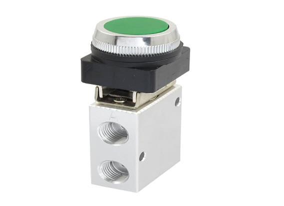
3/2Rollerspringvalveareusingaslimitswitchesand3/2 pushbuttonspringvalveusingforactuatinglimitswitches
9:PneumaticCascadeCircuitA+B+
SecondCycleB-A-Group2Selected

Fig12:ArrangementofLimitSwitch
PowerCircuit–PneumaticCylinder
5/2 Double Piolet valve used for actuating double acting cylinder. Flow control valve used to control flow of compressedairintocylinder.
10:PneumaticCascadeCircuitB-A-
GroupChangingValve
Forgroupingchangingcascadevalve5/2doublepioletvalve using

Fig13:Powercircuit5/2DoublePioletoperatedDCV
International Research Journal of Engineering and Technology (IRJET) e-ISSN: 2395-0056
Volume: 11 Issue: 03 | Mar 2024 www.irjet.net p-ISSN: 2395-0072
Development of A+B+B-A- Circuit
Descriptionofcomponents
1. PneumaticCylinder
Size:Diameter32mmStrokelength50mm
MaxPressure:1.0MPA
Material:Aluminum
Pistonrodmaterial:carbonsteel
WorkingTemperature:20~80°C
PressureResistance:13.5kgf/cm²

2. 5/2
Design:Spooltype
Pressure:1to10Kg/cm2
Temperature:5to550c
PistonPortSize:PT1/8

PositionandWayNo:2Position3Way
PipeThreadDiameter:¼PT
FixingHoleDiameter:5mm
WorkingPressureRange:1.5-8kgf/cm²

Inner

OperatingFluid:Air
PressureGaugeSize:1.6”x1”(DXT)
PressureGaugeRange:0-1MPa
JointPipeBore:G1/4"
2024, IRJET | Impact Factor value: 8.226 | ISO 9001:2008
International Research Journal of Engineering and Technology (IRJET) e-ISSN: 2395-0056
Volume: 11 Issue: 03 | Mar 2024 www.irjet.net

19:
7. PneumaticAirCompressorTubing
Material:Polyurethane
Size:6mmODx4ID
Thickness0.75mm

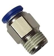
8. QuickConnectorPneumaticAirFittings
Size:6MMPipeX1/8Thread

9. 6mm3wayTQuickJoint
Material:Polyurethan Size:6mm
2395-0072

10. 4WaysPushinAirPneumaticFittingConnector Size:6mm

11 6mmTube1/4"BSPThreadPneumaticConnector
Size:6mm¼BSPThread
12 BrassConnector8mm1/4BSPHose PipeFittingMale andAirPipeAdapterJointPneumaticConnector

Volume: 11 Issue: 03 | Mar 2024 www.irjet.net


Electro-pneumatic is commonly used in many areas of industrial low-cost automation. It is widely used in production,assembly,pharmaceutical,chemicaletc.Electropneumatic control system consists of electrical control systemoperatingpneumaticpowersystem.Solenoidvalveis used as the interface between electrical and pneumatic system. Future work is developing an electro-pneumatic circuitforpneumaticsequentialcircuitA+B+B-A-
Simulationofelectricalladderdiagrameasilyconvertedinto a PLC programming ladder diagram for above sequential motionandsimulatedusingFluidSim-Pneumaticsoftware.
Mostofthepracticalpneumaticsystemsinvolvetheuseof multiple actuators (cylinders, semi-rotary actuators, etc) whichwhenoperatinginspecifiedsequencescarryoutthe desiredcontroltasks.InmulticylinderapplicationsA+B+BA- has wide applications.Sheet metal operation in a press shop, a stamping operation is to be performed using a stampingmachine.Theworkpiecehastobefirstclamped underthestampingstation.Thenthestampingtoolgetsinto position and performs the stamping operation. The work piece must be unclamped only after the operation is completed.Thecascadesystemprovidesastraightforward methodofdesigningsequentialcircuits.Itwillalwaysgivea workablecircuit
[1] V.G.Vijaya“DesignandFabricationofSequencingCircuit with Single Double Acting Cylinder”. International JournalofInnovativeResearchinScience,Vol.2,Issue 11,November2013.
International Research Journal of Engineering and Technology (IRJET) e-ISSN: 2395-0056
Volume: 11 Issue: 03 | Mar 2024 www.irjet.net p-ISSN: 2395-0072
[2] Anand Kumar Singh, Mitesh L Pate“Design and Development of Pneumatic Punching Machine” International Journal for Technological Research in EngineeringVolume4,Issue11,July-2017
[3] Swapnil B. Lande, Tushar S. Shahane, Mitesh M. Deshmukh, Mahesh D. Mange “Design of Pneumatic Vice”InternationalJournalforTechnologicalResearch inEngineeringVolume7,Issue5,January-2020
[4] Shubham Gump Alwar, Darshan Dhabarde, Shubham Gade,AmitKalhane,VishnuNair,Prof.PrafulRandive. “DesignandFabricationofPneumaticCarLifter”IJARIIE Vol-4Issue-22018
[5] Mauton Gbededo and Olayinka Awopetu “Design and ConstructionofAutomatedStampingMachineforSmall Scale Industries” International Journal of Engineering Research & Technology (IJERT) Vol. 6 Issue 12, December–2017
[6] R.Sasikala,M.Rakshana,T.Thinaa,P.Thirupponvel,D. Vasanth “Automatic Bar Bending Machine using PneumaticSystem”InternationalJournalofInnovative TechnologyandExploringEngineering (IJITEE)ISSN: 2278-3075(Online),Volume-9Issue-5,March2020
[7] Bhavik Ranjan Kathe “Pneumatic Can Crusher” International Research Journal of Engineering and Technology(IRJET)Volume7Issue5May2020.
[8] M.PapoutsidakisA.ChatzopoulosD.Tseles“Hydraulics andPneumatics:ABriefSummaryoftheirOperational Characteristics”JournalofMultidisciplinaryEngineering ScienceandTechnology(JMEST)Vol.5Issue10,October –2018
[9] Mr.MayurD.ThoratProf.PatilA.R.“DesignandAnalysis of Pneumatic Pick & Place Mechanism” IJSRDInternational Journal for Scientific Research & Development| Vol. 7, Issue 05, 2019 | ISSN (online): 2321-0613.
[10] Thokale Manoj, Kothwal Satish, Kotkar Rahul, More Suyog, Pawase Mahesh. “Design and fabrication of pneumaticbarbendingmachine”InternationalResearch Journal of Engineering and Technology (IRJET) Volume:04Issue:03|Mar-2017
[11] Jagadeesh T “Pneumatics: Concepts, Design and Applications”UniversitiesPress(India)PrivateLimited ISBN:9788173719417.


Mr. Muhammed Ishack V FinalYearBtech student in the Mechanical Engineering Department at AWH EngineeringCollegeCalicutKeralaIndia
Mr. Ahammed Adil P FinalYearB-tech student intheMechanical Engineering Department at AWH Engineering CollegeCalicutKeralaIndia.
Mr. Amal P K FinalYearB-techstudent in the Mechanical Engineering Department at AWH Engineering CollegeCalicutKeralaIndia
Mr. Rohith V T Final Year B-tech student in the Mechanical Engineering DepartmentatAWHEngineeringCollege CalicutKeralaIndia
Mr.Jibi.R Currently working as an Assistant Professor in the mechanical engineering department at AWH EngineeringCollegeCalicutKeralaIndia He has published 13 International journals and presented two articles in international conference He has more than 11 years experience in teaching and one-year Industrial experience in Press tool and Mold making. His interested area is computer aided design and analysis, Production Technology, Industrial hydraulics and Pneumatics