
International Research Journal of Engineering and Technology (IRJET) e-ISSN: 2395-0056
Volume: 11 Issue: 03 | Mar 2024 www.irjet.net p-ISSN: 2395-0072


International Research Journal of Engineering and Technology (IRJET) e-ISSN: 2395-0056
Volume: 11 Issue: 03 | Mar 2024 www.irjet.net p-ISSN: 2395-0072
M YUVARAJU1 , SUBIYA V M2 , KEERTHANA M3 , ATCHAYA A4
1Assistant Professor, Department of EEE, Anna University Regional Campus, Coimbatore, Tamil Nadu, India 2,3,4PG Scholar, Department of EEE, Anna University Regional Campus, Coimbatore, Tamil Nadu, India
Abstract - This paper presents a comprehensive overview of the real-time implementation of line distance algorithm relay that provides protection for distribution network. The algorithm is tailored to detect and localize faults efficiently, focusing on common fault types like single-phase to ground and three-phase faults. Faults were divided in three major categories: a)Faults in the beginning of the branch b)faults in the middle and c)Faults in end of the branch. The localization method was divided in three steps: a)Faulty branch identification b)Faulty section localization and c)Fault distance estimation. The methodology involves current measurements at the feeders start and voltage drop analysis across feeder branches. The study encompasses a wide range of fault resistance values from 0.1 ohm to 1000 ohm, addressing both single-phase to ground and three-phase faults. The results demonstrate the algorithm effectiveness in identifying faulty sections and precisely locating faults within the grid. Furthermore, SCADA integration enhances the realtime communication withmaintenanceteam, facilitatingswift responses to identifies faults and contributing to heightened grid reliability and operational efficiency. This paper gives an overview of the different advances of the technologyandposes some of the challenges that this technology needs to solve.
Key Words: Fault location, Fault detection, Fault passage indicator, Low voltage distribution grid, Line distance relay, SCADA.
The protective system is very much essential for an ElectricalPowerSystem,whichisusedtoisolatethe faulty equipmentfromthesystemandprotecttheotherequipment fromtheasquicklyaspossible.Incaseofshortcircuitsor faults,theneedforaprotectivesystemisfelt,ifnotisolated itwouldtotallydamagethepower system.Eachpartofthe powersystemisprotected.Theprotectivesystemsinclude circuit breakers and protective relays to isolate the faulty section of the power system from the healthy ones. The function of a protective relay is to sense the abnormal conditions in the power system and gives an alarm or isolatesthatpartfromthehealthysystem.Itminimizesthe damagetotheequipmentandinterruptionstothe service when electrical fault occurs. Faults in typical distribution
grid are responsible for 80% of customer interruptions[1] Unliketransmissionnetworks,distributionnetworkshavea minimal protection scheme[2]. The detection of high impedancefaultsonelectricaldistributionsystemshasbeen oneofthemostpersistentanddifficultproblemsfacingthe electricutilityindustry.Dependingonsomefactorsincluding thefeederstopology,thenumberofestimatesmaybeonthe orderoftens,eachonecorrespondingtoadifferentfeeder lateral. Some attempts have been made to mitigate this problem using expert systems or integrating information providedbymeasurementatthesubstationandthefeeders protection scheme. However, such information is usually insufficient, inaccurate or unavailable. Thus the identification of exact fault location on multi-branched distribution feeders is a problem that has not been yet solved[3].Impedancebasedfaultlocationtechniquecanbe extensivelyusedbecauseoftheirlowimplementationcost. Thetraditionaltechniquesarereactiveinnature,meaning thattheyareusedafterafaulthasalreadyoccurred.These include impedance-based, travelling-wave based and knowledgeexperiencebasedtechniques.Impedancebased methodusevoltageandcurrentmeasurementstodetermine thetypeoffault,whichisthenestimatedonthefaultlocation basedontheapparentimpedance.Althoughtheimpedancebasedmethodisoneoftheoldesttechnique,itisstillused because of its simplicity. Based on the signal used fault location techniques are classified into three different categories [4].
i)Techniquesbasedonfundamentalfrequencyofvoltageand current.
ii)Techniques based on high frequency travelling waves generatedbyfaults.
iii)Artificialintelligenceapproach.
Fault location techniques using fundamental frequency components,alsoknownasimpedancebasedfaultlocation method,extractthefundamentalfrequencycomponentsof thevoltageandcurrentsignalstocalculatetheimpedanceof thefaultedline.Twoapproachesforfaultdetectioninlow impedance fault was examined, one based on current measurement at the feeders beginning and the other on highestvoltagedropacrossfeederbranches.Researchhas

International Research Journal of Engineering and Technology (IRJET) e-ISSN: 2395-0056
Volume: 11 Issue: 03 | Mar 2024 www.irjet.net p-ISSN: 2395-0072
focus on fault diagnosis in low voltage smart distribution gridsusinggradientboostingtreemodelstodetect,identify, andlocalizesingle-phase-to-groundandthree-phasefaults. Additionallyanovelfaultdetectionandlocalizationmethods forlowvoltagedistributiongrid,showcasingapproachesto enhancegridreliabilityandefficiency.
II.SYSTEM DESCRIPTION
A.POWER SYSTEM FAULT ANALYSIS
Thefaultanalysisofapowersystemisrequiredinorderto provideinformationfortheselectionofswitchgear,setting of relay and stability of the system operation. A power systemisnotstaticbutchangesduringoperation(switching on or off generators) and during planning (addition of generatorsandtransmissionlines).Thusfaultstudiesneed toberoutinelyperformedbyutilityengineers.Faultsusually occur in power system due to either insulation failure, flashover, physical damage or human error. In the power system,thereareprimarilytwotypesoffaults.
i)Asymmetricalfault
ii)Symmetricalfault
ASYMMETRICAL FAULT: When the network is unsymmetrically faulted or loaded, neither the phase currents nor the phase voltage will possess three phase symmetry. Most of the system faults are unsymmetrical faults. It consists of unsymmetrical short circuit fault or unsymmetricalfaultsthroughimpedance,oropenconductor faults.Iftheinsulationthesystemfailsatanypointorifa conductingobjectcomesincontactwithabareconductoran unsymmetrical short circuit fault is said to occur. If unsymmetricalfaultoccurtheunbalancedcurrentwillflow in the system. We are using symmetrical components to analyze unsymmetrical faults. To determine positive, negative and zero sequence impedance, we can use Thevenin’stheoremorbusimpedancematrix.
SYMMETRICAL FAULT: Whenthenetworkissymmetrically faulted,thephasecurrentsandphasevoltagepossessthree phase symmetry.[i.e. equal magnitude and equal phase shift(1200)].Symmetricalfaultisthemostseverefaultand most amenable to calculate. The current flowing immediately after the fault consists of an AC component whicheventuallyreachessteadystateandafastdecayingDC componentwhichdecaystozero.Foranalysis,onlytheAC componentisconsidered.
Faultcurrent|If|=Eth/(Zth+Zf)
B.FAULT LOCATION METHODS
Twoofthemostcommonmethodsusedforfaultlocationare theimpedance-basedmethodandtravelingwavemethod[5] . The impedance-based method uses phasor voltages and
currents captured by fault recorders and known system parametersofthelinetocalculatethefaultlocation.Oneof the methods introduces the digital fault locator, which measurestheratioofreactanceofalinefromthepointofthe faulttothedevice.Thelineimpedanceperunitlengthcan then be used to calculate the distance to the fault. Fault resistance though can impact the accuracy of this method becausehigherresistanceaffectsprecision[6] andtheother methodbuildsbymeasuringthereactanceatoneendofthe lineandcalculatingphaseshiftbetweentotalcurrentflowing fromoneendofthelineandcurrentthroughfaultresistor[7] Some of the research on the impedance based method utilizes both voltage and current measurements for fault locationondistributionnetwork[8-9]
Alinedistancerelay(LDR)inalowtensiondistributiongrid can be used to identify faults based on the impedance method. This method involves measuring the impedance betweentherelayandthefaultlocation,whichcanhelpin determiningthedistancetothefaultandthelocationofthe fault on the grid. The LDR operates by comparing the currentflowingthroughtheprotectedlinewiththecurrent flowingthroughthefaultyline. Whenthefaultoccurs,the currentthroughthefaultylineincreases,causingtherelayto trip. The LDR can be set to rip when the current ratio exceeds a certain value, indicating a fault on the grid. By measuringtheimpedance between the relayandthe fault location,theLDRcandeterminethedistancetothefaultand helpinlocatingthefaultonthegrid.Thisinformationcanbe used to isolate the faulty section of the grid and restore powertotheaffectedarea.Distancerelaysareplacedinthe particular zone and usually communicate with the main systemandotherrelaysusingthepilotrelayingscheme.As the impedance of the distribution relay is directly proportionaltoitslength,itcanbeconcludedthatadistance relay can only operate if fault has occurred within a predetermined distance. Distance relays are most useful for reasonable line lengths(upto 20Kms or so) because their operatingcharacteristicsarebasedonthelineparameters.
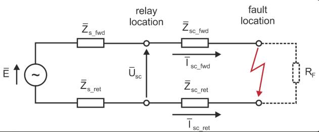
Adistanceorimpedancerelayisessentiallyanohmmeter andoperateswhenevertheimpedanceoftheprotectedzone fallsbelowthepre-determinedvalue.Therearetwotypesof distancerelays

International Research Journal of Engineering and Technology (IRJET) e-ISSN: 2395-0056
Volume: 11 Issue: 03 | Mar 2024 www.irjet.net p-ISSN: 2395-0072
i)Definite-distancetypeimpedancerelay
ii)Time-distanceimpedancerelay
Definite-distance type impedance relay
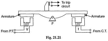
Fig 2-Definite-distance type impedance relay
Under normal conditions: The pull due to the voltage elementisgreaterthanthatofthecurrentelement.So,the relaycontactsremainopen.Whenfaultoccurs:Thenapplied voltagetotherelaydecreasesandthecurrentincreases.The ratioofvoltageandcurrenti.e.,impedancefallsbelowthe pre-determinedvalue.S0,thepullofthecurrentelementwill exceedthatduetothevoltageelementandthiscausesthe beamtotiltinadirectiontoclosethetripcontacts.
Time-distance impedance relay
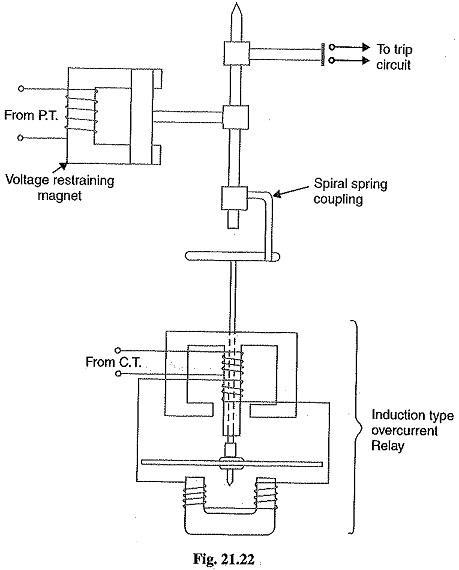
Fig 3-Time-distance impedance relay
A time-distance relay has its vital feature that it automatically adjusts its operating time according to the distanceoftherelayfromthefaultpoint.
i) Operating Time is directly proportional to voltage and inverselyproportionaltocurrent.
ii) OperatingTimeisdirectlyproportionaltoimpedance.
iii)OperatingTimeisdirectlyproportionaltoDistance.
Undernormalconditions: Thepullofthearmatureismore than that of induction element and hence the trip circuit contactsremainopen.
Under fault occurs: The disc of the induction current element starts to rotate at a speed depending upon the operatingcurrent. Astherotationofthediscproceeds,the spiral spring coupling is wound up till the tension of the spring is sufficient to pull the armature away from the voltageexcitedelement.Thespindlecarryingthearmature andbridgingpiecemovesrapidlyinresponsetothetension of the spring and trip contacts are closed. This opens the circuitbreakertoisolatethefaultyportion.
Specificallydesignedfordetectinghighimpedancefaultsin low voltage networks, these relays play a crucial role in identifying and localizing faults that may not be easily detectedbytraditionalprotectionmethods.
This scheme integrates smart distribution network to automate the fault location process in low voltage grids, reducing reliance on manual reporting and enhancing the efficiencyoffaultdetectionandlocalization.
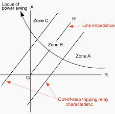
Fig 4-Distance relay operating curve
Distance relays are double actuating quantity relays with onecoilenergizedbyvoltageandtheothercoilenergizedby current.Theoperatingtorqueproducedissuchthatwhen V/I reduces below a specified value, the relay operates. Duringafaultondistributionline,thefaultcurrentincreases and the voltage at fault point reduces. The ratio V/I is measured t location of CTs and PTs. The voltage at PT

International Research Journal of Engineering and Technology (IRJET) e-ISSN: 2395-0056
Volume: 11 Issue: 03 | Mar 2024 www.irjet.net p-ISSN: 2395-0072
location depends on the distance between the PT and the fault.Iffaultisnearer,measuredvoltageislesser.Iffaultis further,measuredvoltageismore.Henceassumingconstant fault resistance each value of V/I measured from relay locationcorrespondstodistancebetweentherelayingpoint and the fault. Hence such protection is called Impedance protectionorDistanceprotection. Therelayoperateswhen the ratio V/I i.e., impedance is less than a predetermined value.AstheratioV/Iaffectstheperformanceoftheserelays arealsocalledratiorelays.DependentontheratioofVandI, therearefivetypesofdistancerelay.TheyareImpedance relay,Reactancerelay,Admittancerelay(mhorelay),Ohm relayandOffsetmhorelay.
E.IMPEDANCE BASED METHOD
Impedance based fault location algorithm calculate fault distance using the per unit length impedance of the line, voltage and current data, and circuit analysis techniques, suchasKirchhoff’svoltageandcurrentlaws.Single-terminal and two-terminal algorithms are the two main groups of impedancebasedFLA.
F.FAULT PASSAGE INDICATOR
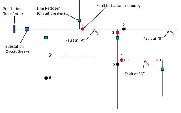
AFaultPassageIndicator(FPI)isadeviceused inelectric power distribution system. It operates by monitoring the electromagneticfieldaroundtheconductorcausedbyhigh current flows, which are associated with faults. When the faultoccurs,theFPIdetectsthechangeinthemagneticfield andprovidesanalarmbycommunicatingthrougharemote terminal unit (RTU) to the distribution system. A Fault Passage Indicator in a low voltage distribution grid is a device used to detect and indicate faults that occur in the electricaldistributionnetwork.Itworksbymonitoringthe system24/7forfaultoccurrencesandquicklyidentifyingthe faultlocationtoreducedowntime.
G.CURRENT TRANSFORMER
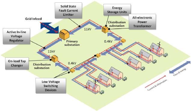
In a low voltage distribution grid, a current transformer (CT) can be used in conjunction with a fault passage indicator(FPI)andalinedistancerelaytolocalizefaults.The CTconvertshighcurrentlevelsinthedistributionnetwork
toalower,statelevelthatcanbemeasuredandmonitored. The FPI uses these current and voltage measurements to detectandindicatefaults,whilethelinedistancerelayuses the positive-sequence impedance between the relay and faultlocationtoaccuratelypinpointthefaultlocationwithin the distribution grid. The CT plays a crucial role in this processbyprovidingthenecessarycurrentmeasurements fortheFPIandlinedistancerelaytooperateefficiently.
In a distribution line, Potential transformers are typically installed at substations to provide accurate voltage measurementsformonitoringandcontrolofthesystem.The operation of a potential transformer in a distribution line involvesthevoltageisinducedintheprimary windingofthe potential transformer due to the voltage across the distribution line. The primary winding is connected in paralleltothedistributionline,andthesecondarywindingis connectedtothemeasuringandprotectiondevices.When abnormalconditionisdetectedinthedistributionline,the potentialtransformerprovidesaccuratevoltagesignaltothe protectiverelays,whichacttoisolatethefaultandprevent damagetothesystem.ThePTbehavesasanordinarytwowinding transformer operating on no load, and the VA ratingsofPTsarelow,rangingfrom50to200VA.
A.IMPEDANCE
Impedance relay consists of two elements, the voltage element of the relay is excited through a potential transformer from the line to be protected. The current elementoftherelayisexcitedfromthecurrenttransformer inserieswiththedistributionsystem.Thetorqueproduced bythecurrentelementisbalancedagainsttorqueproduced bythevoltageelement.Thusthecurrentelementsproduces operating torque, pick torque which can be said to be positive torque. The voltage element produces remaining torque,resettorquewhichcanbesaidtobenegativetorque. Sothisrelayisvoltagerestrainedovercurrentrelays.

International Research Journal of Engineering and Technology (IRJET) e-ISSN: 2395-0056
Volume: 11 Issue: 03 | Mar 2024 www.irjet.net p-ISSN: 2395-0072
Setting up the FPI:Beforestartingtheimplementation,the FPIrequiressomesettingsforfaultdetectionwhichisovercurrentthresholdandtimeofdetection.
FPI indication: The FPI normally includes the visual indication of the fault i.e., a LED, flash etc. A particular indication system is a glass filled with liquid and a red pigment[10]. When the fault is detected, a metal ball in the bulbmovesduetothestrongmagneticfieldassociatedwith the large current, shaking the pigment and coloring the liquid.Inurban,highlypopulatedareasitcanbedifficultto accessthesubstations,orthesubstationislocatedinprivate property.Forthisreason,alternativesystemistoobtainthe FPI indication. The FPIs incorporated the ability of communicating through radio frequency with the SCADA system.However,SCADAsystemshavenotbeenwidelyused in distribution level. Later, other communication such as Power Line Communication (PLC) in combination with RemoteTerminalUnit(RTU).
Resetting the FPI:OncetheFPIhastripped,theindication mustremainontillthelocatingcrewclearthefault.When thefaultisclearedandtheserviceisrestored,theFPIhasto return back to its original state, so that the device has to returnbacktonormalstate.
Severalmethodshavebeenproposedforfaultlocationbut arenotreadilyapplicabletodistributionsystems.Thisisdue to heterogeneous lines, lateral branches, and load taps in distributionsystem.Theprimarymethodsusedtolocatethe location of faults in distribution networks are impedance, travelingwaveandpostdiagnosticmethod[11].Inadditionto allthemethods,theFaultIndicationisthemostpracticaland affordablewayfordistributionsystems,thusprovidingthe bestprobablefaultlocation.
Inlowtensiondistributionnetwork,thefaultdetectionand localization process using line distance relay involves the measurementofcurrentandvoltagetoaccuratelyidentify andlocatefaults. Gong&Guzmanproposedafaultlocation technique that utilizes current and voltage measurements obtained from digital relays. These measurements are crucial for impedance-based fault location methods in distributionnetworks,allowingforprecisefaultlocalization. Additionally, the use of Fault Passage Indicators (FPIs) enhances fault detection by detecting the passage of fault currentthroughthelateral comingfromthebusonwhich theyareinstalled. FPIsplayavitalroleindeterminingthe locationoffaultsbyanalyzingcurrentsignalsfromcurrent transformersandvoltagesignalsfromvoltagetransformers at the relay. By combining these measurements and techniques,thefaultdetectionandlocalizationsysteminlow
voltagedistributionnetworkcanswiftlyidentifyfaultsand accuratelypinpointtheirlocationsforefficientmaintenance and restoration actions. Distance protection, specifically usingdistancerelays,isacrucialmethodforsafeguarding transmissionand distributionnetworks. Theserelays are designedtotripcircuitbreakerswhenafaultoccurswithina specified “reach” distance, providing more sophisticated fault detection than simple overcurrent relays. The developmentofdistancerelayshassignificantlyimproved the protection of overhead lines and improved the protection of overhead lines and underground cables at varioussystemvoltages,makingthemeconomicallyviable formostsystems. Distancerelayingisessentialpowerlines by estimating the physical distance between the relay’s sensing transformer and the fault location. It offers more reliablezoneprotectionbycalculatingtheimpedanceofthe protectedzone andtripping breakersifa faultis detected withinthatzone. Theuseofdistancerelayshasevolvedto provideprimaryand remoteback-upfunctionsina single operating arrangement, offering quick service for short circuitsalongprotectedelementsandenablinghigh-speed auto-reclosingformajortransmissioncircuits.
Line distance relays and fault passage indicator are strategically placed throughout the grid. These devices collect data on fault inception, fault type (ex., phase-toground, phase-to-phase), and for line distance relays, the apparent impedance to the fault location. This data is transmittedviatheSupervisoryControlandDataAcquisition (SCADA)systemtocentralserver.
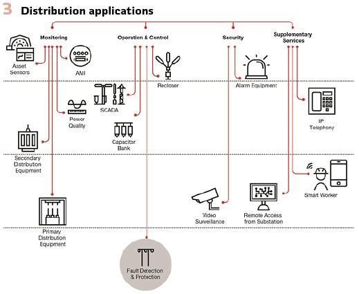
Fig 7-Distribution applications
B.ALGORITHM DESIGN
Afaultlocalizationalgorithmisdevelopedandimplemented oncentralserver.Thisalgorithmutilizesthereceiveddata from the relay and FPIs to estimate the fault location. Common approaches include impedance-based methods using line distance relay data, travel time-based methods

International Research Journal of Engineering and Technology (IRJET) e-ISSN: 2395-0056
Volume: 11 Issue: 03 | Mar 2024 www.irjet.net p-ISSN: 2395-0072
using FPI data, or a combination of both for enhanced accuracy.
TheSCADAsystemandthefaultlocalizationalgorithmneed tobeconfiguredtoseamlesslyexchangedata.Thisinvolves establishing a communication protocol the defines the messageformat,datastructure,andtransmissionmethods forfaultdatabetweentherelays/FPIsandthecentralserver.
Once the algorithm and communication protocols are established, comprehensive testing and validation are crucial.Simulatedfaultscenariosare injectedintothegrid, and the algorithm’s response is compared against actual fault locations identified through manual field inspection. Thisprocesshelpsinrefiningthealgorithmandensuringits accuracyandreliability.
Uponsuccessfultestingandvalidation,thefaultlocalization system is deployed on the actual distribution grid. The systemcontinuouslymonitorsthegridforfaults,andwhena faultoccurs,thealgorithmestimatesandtransmitsthefault location tothesystemoperators,enablingthemtotakeswift correctiveactionsandminimizeoutagedurations.
F.SCADA COMMUNICATION
The implementation of SCADA communication for fault localization in low tension distribution grids involves a systematic process to enhance fault detection and localization efficiency. Initially, the optimal placement of Fault Passage Indicator (FPIs) is determined through optimization tasks to ensure network reliability and costeffectiveness.Substantially,afaultlocalizationalgorithmis developed,leveragingtheequipmentalreadyinstalled,such as fault indicators, to achieve precise fault localization in termsoftimefrequency.Thisalgorithmisintegratedwith theSCADAsystemtoenablereal-timedatatransmissionand remote monitoring capabilities, facilitating fault detection and localization with minimal time delays. The SCADA communication system plays a pivotal role in enabling communication between system components like relays, FPIs and the SCADA system, ensuring efficient data transmissionandenhancingfaultdetectionandlocalization capabilities. This helps to protect the power system from damagetotheequipments.
Thealgorithmforsettingalinedistancerelayinlow voltagedistributionnetworksinvolvestechnicalefficiency criteria and probability statistical methods. It focuses on studying and developing technical effects to enhance the
efficiency of relay protection schemes. It recommends setting options for different stages of protection based on sensitivityandminimizingexcessiveactions,optimizingthe firststageforhigh-speedoperation,andensuringtechnical efficiencyforeffectivedistancerelayprotectionfunctioning. It aims to improve the reliability and performance of distancerelayprotectionsystemsinlowvoltagedistribution networks.
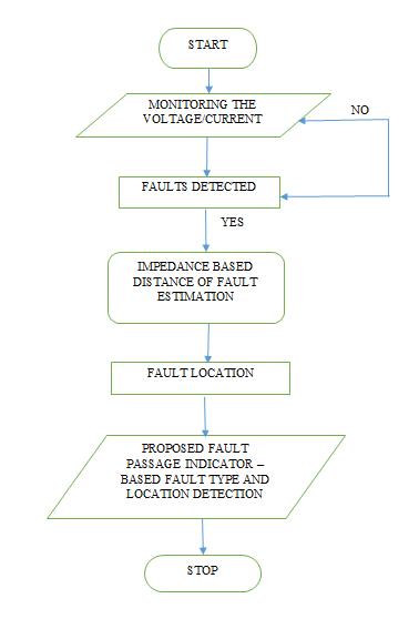
Step2-Measuretheelectricalimpedanceofthe network, whichistheratioofvoltagetocurrentataspecificpointon line.
Step 3-Distance relays use voltage and current measurements to calculate the impedance to the point of fault.
Step 4-Distance relays calculate the ratio of voltage to current to apparent impedance, which is crucial for fault detectionandlocalization.
Step5-Whenthefaultisdetected,protectiverelaysexitsto protectthepowersystemfromfaultsanddamageotherwise gotostep2.
Step6-Stop.

International Research Journal of Engineering and Technology (IRJET) e-ISSN: 2395-0056
Volume: 11 Issue: 03 | Mar 2024 www.irjet.net p-ISSN: 2395-0072
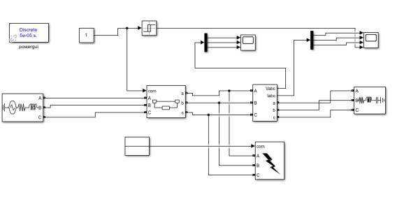
Fig 8-Transmission line protection
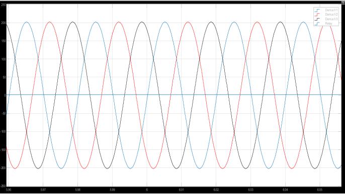
Fig 9-Simulink graph for Power system protection
Fig-8&9-Powersystemprotectioninvolvessimulatingand optimizing power system to ensure reliable and efficient operation.Thisprocessincludesmodelingpowergeneration equipment, integrating power plant into the electric grid, andestimatinggeneratorcontrolsystemparameter.
Transmission or distribution line simulation can be done usingMATLAB/Simulinksoftware.
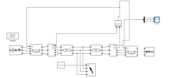
Fig 10-Transmission line protection Simulink block
Distribution systems deliver electricity from transmission lines to end-users at lower voltages within localizedareas.Whilesharingsimilaritieswithtransmission linesimulators,distributionsystemmodelsoftenfocuson differentaspectslikeloadvariations,voltageregulation,and networkconfigurationforoptimalperformance.Protection schemesfordistributionsystemsmaydifferfromthoseused intransmissionlinesduetothevaryingfaultcharacteristics andnetworkconfigurations.
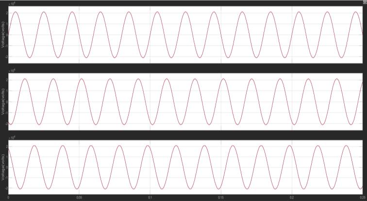
Fig-11 involves modeling the transmission line and simulatingtheimpactsonthesystem.Inthesameway,low voltagedistributiongridcanalsobeprotected.
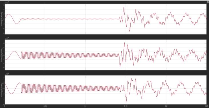
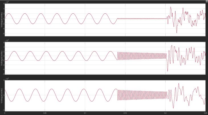
Fig-12 and 13 allows for a detailed examination of fault scenarios in low voltage distribution networks, providing insights into fault detection and localization strategies for enhancingsystemreliabilityandperformance.Bysimulating faults at different positions along the distribution lines, voltageandcurrentwaveformsareanalyzedtodetermine thefaultlocationaccurately.

International Research Journal of Engineering and Technology (IRJET) e-ISSN: 2395-0056
Volume: 11 Issue: 03 | Mar 2024 www.irjet.net p-ISSN: 2395-0072
TheMATLAB/Simulinkblockforsimulatingalinedistance relayindistributionnetworkinvolvesmodelingandtesting adigitaldistancerelayforlineprotection.Thissimulation includesthemeasurementofimpedancechangesbetween fault-free and faulted lines to detect fault accurately. The simulationutilizesMATLAB/Simulink’scapabilitiestomodel the relay’s behaviour, test its performance, and ensure reliableprotectionofthepowersystem.
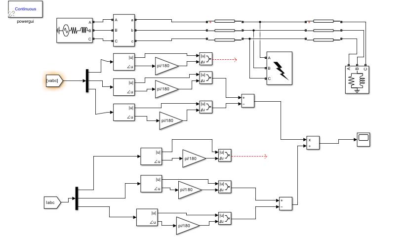
Fig 14-Line distance relay Simulink block
VII.RESULTS AND DISCUSSIONS
The proposed fault location method relies on the electric waveforms recorded at the secondary electrical substationbyutilizingLineDistanceRelayandFaultPassage Indicatorwithcurrenttransformerandvoltagetransformer.
VOLTAGE AND CURRENT WAVEFORM
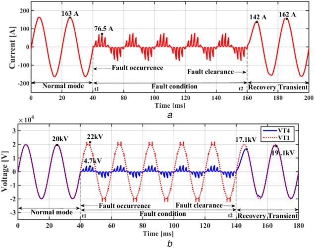
Fig 15-Fault location
During a fault in a low voltage distribution network, the voltage and current waveforms undergo specific changes thatarecrucialforfaultdetectionandlocalization.Whena fault occurs, the current waveform experiences a sudden increase due to the short circuit created by the fault. This
increase in current is detected by protective relays, triggeringthemtoisolatethefaultysectionfromtherestof thenetwork.Thevoltagewaveform,ontheotherhand,may exhibitvariationsdependingonthetypeandlocationofthe fault.Theanalysisofvoltageandcurrentwaveformsduring a fault is essential for accurate fault detection and localizationinlowvoltagedistributionnetworks.
Thearea offaultclearanceisofimportanceforthepower distribution company since it is imperative to uphold the reliability of power delivery to reach a high level of satisfaction with the customers and reduce regulatory imposed negative incentives. The power restoration and fault location process is highly reliant on technicians. The processvariesdependingoninwhichlevelofthegridthe faultoccurs.Thisreportprimarilyfocusedonthelocalgrids involtagelevels.Withtheaimofidentifyingasinglemethod applicabletoallfaults,inallgridstructures,whichreduces theinfieldworkandthetotaloutagetime[12].Thedifferent methods for fault location are Impedance based method, Traveling wave and Knowledge based methods. The Traveling wave and Knowledge based methods both displayed a high level of accuracy, but neither could be regardedasmethodsforfullscaleimplementation.Thehigh cost for implementation and the unavailability of commercially ready equipment where the main objective against the traveling wave method. The main benefits of impedance method was the low implementation cost and highaccuracy.
Thepurposeofthispaperistoidentifyfaultlocationusing impedance based method. In low voltage distribution networks,faultoccurrenceisacommonchallenges,withthe majorityoffaultsbeingtemporaryandself-clearing,ranging from 75%-90%. Those temporary faults typically last between 15 to 400 minutes per customer per year. With about 80% of all faults occurring at the distribution level, fault location in distribution networks has become a significant area of interest, previously more focused on transmission networks. SCADA systems in distribution systems highlights their significant role in enhancing performance,reliability,anddurability.SCADAsystemsare crucialforpowerdistribution,utilizingmodemtechnologies toautomatetasksandimproveoverallsystemefficiency.In summary,thepaperrecommendsthefollowingcriteriafor selecting the most suitable fault location algorithm i)Line distancerelaydataii)FaultPassageIndicator.Faultscaused by animal or tree contact with distribution network, or insulation failure in power system equipment have one singlelocation.However,whenlightingstrikesanoverhead line,thevoltageacrosstheinsulatorissolargethatitcauses a back flash-over and fault. In this case, impedance-based faultlocationalgorithmisusedtolocatefault.

International Research Journal of Engineering and Technology (IRJET) e-ISSN: 2395-0056
Volume: 11 Issue: 03 | Mar 2024 www.irjet.net p-ISSN: 2395-0072
[1]Nikolaos Sapountzoglou, Bertrand Raison, Nuno Silva “Fault Detection and Localization in LV smart grid” 2019 IEEEMilanPowerTech-2019.
[2]RaphaelMarguet“Improvedfaultlocalizationmethodfor electricalpowerdistributionnetworks”UniversiteGrenoble Alpes,2015.
[3]G.D.Ferreira,A.S.Bretas,A.L.Bettiol,A.Carniato,L.F.N. Passos,A.H.Ferreira,J.E.M.Silva”Anintegratedtechnique for fault location and section identification in distribution systems”ElectricPowerSystemDesignvolume,115October 2014,Pages65-73.
[4]Chaoqi Ji ”Impedance based Fault location methods for transmission line connecting wind farm plants” Clemson University-2012.
[5]Wesley Fluty “Fault location techniques using the tradition techniques by traveling wave method and the discretewavelettransform”2019.
[6]M.T.Sant,Y.G.Paithankar,“Onlinedigitalfaultlocatorfor overheadtransmissionline,”ProceedingsoftheInstitution ofElectricalEngineers,vol.126,no.11,Nov.1979,pp.11811185.
[7]A. Wiszniewski, “Accurate fault impedance locating algorithm,”IEEProceedingsGeneration,Transmissionand Distribution,vol.130,no.6,Nov.1983,pp.311-314.
[8]W.XiuandY.Liao,"Faultlocationobservabilityanalysis onpowerdistributionsystems,"ElectricPowerComponents andSystems,vol.42,no.16,2014,pp1862-1871.
[9] Y. Liao, "A novel method for locating faults on distribution systems," Electric Power Systems Research Journal,vol.117,Dec.2014,pp.21-26.
[10] Carlos Gonzalez-de Miguel, Tom De Rybel , Johan Driesen1”ApproachingtheFaultPassageIndicator”Journal ofenergychallengesandmechanics.
[11]J.Liang,T.Jing,H.Niu,andJ.Wang,“Two-terminalfault locationmethodofdistributionnetworkbasedonadaptive convolutionneuralnetwork,”IEEEAccess,vol.8,pp.54035–54043,2020.2020.
[12]M.YuvarajuandM.Divya,"ResidentialLoadForecasting by Recurrent Neural Network on LSTM Model," 2020 4th International Conference on Intelligent Computing and ControlSystems(ICICCS),Madurai,India,2020,pp.395-400, doi:10.1109/ICICCS48265.2020.9121116