
International Research Journal of Engineering and Technology (IRJET) e-ISSN: 2395-0056
Volume: 11 Issue: 03 | Mar 2024 www.irjet.net p-ISSN: 2395-0072
International Research Journal of Engineering and Technology (IRJET) e-ISSN: 2395-0056
Volume: 11 Issue: 03 | Mar 2024 www.irjet.net p-ISSN: 2395-0072
CH.V.S
Murthy1 , K.Sri Hari Rao2 , S .kalyani3 , P .Samba Siva Rao4 , P. Adithya5 , S Siva Nagi Reddy6
1 Associate professor, Department of Electronics and Communication Engineering, Nri institute of technology, Perechala, Andhra Pradesh ,India
2 Associate professor, Department of Electronics and Communication Engineering, Nri institute of technology, Perechala, Andhra Pradesh, India
3 UG Students, Department of Electronics and Communication Engineering, Nri institute of technology, Perechala, Andhra Pradesh, India ***
Abstract - The design of a small circular micro strip patch antenna covering the 5.7 to 6.15 GHz frequency is presented in this work for WLAN applications. The antenna is constructed using a micro strip line feed and a 1.4 mm thick FR-4 (lossy) substrate with a relative permittivity of 4.4. The circular patch is chosen radius is 8 mm. In order to optimize the size and performance of the suggested antenna, a slot measuring 19 mm x 19 mm is etched onto the ground plane. By Using CST Microsoft Studio Simulation Software, the antenna is designed. Many antenna properties are studied, including radiation efficiency, directivity, antenna gain, percentage bandwidth, return loss, and radiation pattern. We have designed a circular micro strip patch antenna that operates at a frequency of 5.8GHz in this paper. The patch antenna is designed on a FR4 (Flame Retardant 4) substrate, which has a height of 1.6mm and a dielectric constant of εr= 4.4 & Copper material is used in patch and ground design.
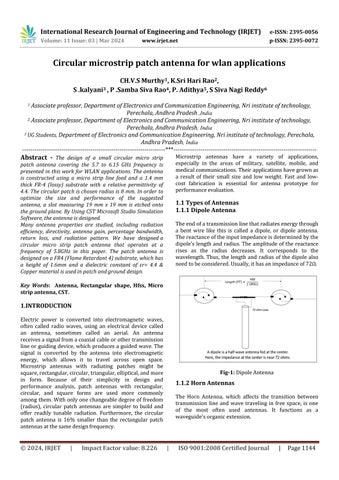
Key Words: Antenna, Rectangular shape, Hfss, Micro strip antenna, CST.
1.INTRODUCTION
Electric power is converted into electromagnetic waves, often called radio waves, using an electrical device called an antenna, sometimes called an aerial. An antenna receivesasignalfromacoaxialcableorothertransmission lineorguidingdevice,whichproducesa guidedwave.The signal is converted by the antenna into electromagnetic energy, which allows it to travel across open space. Microstrip antennas with radiating patches might be square,rectangular,circular,triangular,elliptical,andmore in form. Because of their simplicity in design and performance analysis, patch antennas with rectangular, circular, and square forms are used more commonly amongthem.Withonlyonechangeabledegreeoffreedom (radius), circular patch antennas are simpler to build and offer readily tunable radiation. Furthermore, the circular patch antenna is 16% smaller than the rectangular patch antennasatthesamedesignfrequency.
Microstrip antennas have a variety of applications, especially in the areas of military, satellite, mobile, and medicalcommunications.Theirapplicationshavegrownas a result of their small size and low weight. Fast and lowcost fabrication is essential for antenna prototype for performanceevaluation.
1.1.1
Theendofatransmissionlinethatradiatesenergythrough a bent wire like this is called a dipole, or dipole antenna. Thereactanceoftheinputimpedanceisdeterminedbythe dipole's length and radius. The amplitude of the reactance rises as the radius decreases. It corresponds to the wavelength. Thus, the length and radius of the dipole also needtobeconsidered.Usually,ithasanimpedanceof72Ω.
1.1.2
The Horn Antenna, which affects the transition between transmission line and wave traveling in free space, is one of the most often used antennas. It functions as a waveguide'sorganicextension.
International Research Journal of Engineering and Technology (IRJET) e-ISSN: 2395-0056
Volume: 11 Issue: 03 | Mar 2024 www.irjet.net p-ISSN: 2395-0072
In order to enable wideband operation, the authors insuggested using a circular microstrip antenna with a circular slot etched on the circular patch. The FR4substrate design parameters were (εr =4.3) with a 25 mm×25 mm ground plane, a 8 mm radius circular patch, anda1mmsubstratethicknessusingComputerSimulation Technology(CST)tool,theydesignandmodel theantenna tofunctionat5.8GHz.Theydiscoveredthat660MHzwasa broader bandwidth with a low return loss of -29dB. This review focuses on microstrip patch antennas incorporatingslots.Researchersexploretheeffectsofslots onvariousantennaparameters,includingbandwidth,gain, radiation pattern, and return loss. The bandwidth of microstrip patch antenna increases with the help of slots. Antennastructurecanbemademorecompactandthegain of microstrip patch antennas increased by using varied shaped slots. A brief overview of the design of circular microstrip antennas,where it is concluded that these antennascanbedesignedfora varietyoffrequencybands andthatdifferentsubstratematerialscanbeexcitedbythe antenna using a variety of feeding techniques, including coaxial, strip line, aperture coupling, and proximity coupling. Over the past 20 years, communications have concentrated on microstrip patch antennas because of their advantages. The microstrip patch antennas are havinglimitinggain,narrowbandwidth,depletedradiation pattern, and surface wave excitation are further disadvantages.
3.1 Fundamental Parameters of Antennas
The features of the antenna that is employed in a typical wireless communication system determine its properties. Sometimes,thesevariablesarealsoreferredtoasantenna attributes or characteristics. A summary of several essentialantennapropertiesisprovidedbelow.
DirectivityandGain
RadiationEfficiencyandPowerGain
InputImpedance
EffectiveLength
Bandwidth
EffectiveAperture
AntennaPolarization
Amicrostrip patch antennais a type of antenna that operates in the microwave frequency range. Let’s delve intoitsdetails:
A microstrip patch antenna consists of a thin metallic patch (usually made of conductive material) on a dielectric substrate. The other side ofthesubstrateisgrounded.
Thethicknessofthedielectricslabtypicallyranges from0.03λto0.05λ.
The dimensions of the patch fall within the range ofλ/3toλ/2, with the dielectric constant of the slabvaryingfrom2.2to12.
These antennas are often etched onto circuit boards using photo-etching technology, making themlow-profileandsuitableforintegration.
Thereareseveralvarietiesofmicrostrippatchantennas, including:
Rectangular Patch Antenna: A straightforward rectangledesign.
Antennainthecircularpatchdesign.
Theantennaisshapedlikeatriangle.
Dual-Frequency Patch Antenna: Made to function ontwofrequencies.
Several patches piled vertically is known as a stackedpatchantenna.
Aperture-CoupledPatchAntenna:Connectedviaa groundplaneaperture.
Fig -3:DifferentShapesofAntennas
International Research Journal of Engineering and Technology (IRJET) e-ISSN: 2395-0056
Volume: 11 Issue: 03 | Mar 2024 www.irjet.net p-ISSN: 2395-0072
Microstripantennasfindapplicationinavarietyofsectors, including radars, satellites, spacecraft, missiles, airplanes, wireless communication systems, and mobile phones. The wirelesscommunicationsindustryusestheseantennas.
Microstrip patch antennasfind widespread applications in variousfieldsduetotheiruniquecharacteristics.
WirelessCommunicationSystems
SatelliteCommunication
MobileRadiosandHandheldDevices
MedicalImagingandMaterialCharacterization
UnmannedAerialVehicles(UAVs)
Apowerful 3DEManalysistoolkitforcreating,evaluating, and improving electromagnetic (EM) systems and components is called CST Studio Suite. Electromagnetic fieldsimulationfindswidespreadapplicationinCSTStudio Suite. The program CSTStudioSuite2023 is used to design andmodeltheantenna.
The CST Studio Suite includes a number of modules, such as:
SolversforElectromagneticSimulation:applicable toEMdevicesandsystems.
Electromagnetic Design Environment: An EM system'sgraphicaluserinterface.
Automatic Optimization: EM system optimization procedures.
Projectmanagementforsimulationismadeeasier bysystemsmodeling.
Workflow Integration: Simplifies import and sharingofdata.
4.1
ThesearetheproceduresforutilizingCSTStudioSuiteto designandsimulateamicrostrippatchantenna.
a. Create Geometry: Specify the patch's length, breadth,andformaswellasthecharacteristicsof thesubstratematerial.Installthegroundplaneand microstrip feed line in the feeding mechanism. Indicate the thickness of the substrate and the dielectricconstant.
b. ExcitationandBoundaryConditions:Givethefeed linetheproperexcitation,whichisoftenavoltage source. Define the behavior of the antenna by setting up boundary conditions (such as a radiationbarrieroraperfectelectricconductor).
c. Meshing: For a precise simulation, break the geometryupintosmallercomponents. Tobalance accuracy and computational efficiency, adjust the meshsettings.
d. Configuring the Solver: Select the proper solver (time domain or frequency domain, for example). Indicatethefrequencyrangeofthesimulation(for radiationpatterns,S-parameteranalysis,etc.).
e. SimulationandAnalysis:Runthesimulationtoget information on radiation patterns, impedance matching, and S-parameters (return loss, VSWR). Examinethebandwidth,directivity,andresonance frequency.
f. Simulation Outcomes: CST Studio Suite yields a range of output outcomes. Utilize modeling programs (such as CST Microwave Studio and HFSS)toconfirmtheantenna'sfunctionality.
In the Existing Antenna System the design of a compact circular microstrip patch antenna for WLAN applications which covers the band 5.15 to 5.825 GHz. The antenna is designed using 1.4mm thick FR-4 (lossy)substrate with relative permittivity4.4anda microstriplinefeed is used. The radius of the circular patch is chosen as 7.62mm. To reduce the size and enhance the performance of the antenna, a circular slot is loaded on circular patch and a square slot is etched on the ground plane of dimension 30mm×30mm. Design of the antenna is carried out using CST Microsoft Studio Simulation Software. The antenna resonates at 5.5 GHz with a wider bandwidth of 702 MHz and it provides low return loss of -31.58 dB, good gain of 3.23dBanddirectivityof4.28dBiandefficiencyofaround 79% against the resonance frequency. The 5.15 to 5.825 GHz frequency is covered by the microstrip line feed used inWLANapplications.TheCSTStudioSuite2015software isusedtodesignandsimulatetheantenna.
Table -1: Designparametersandtheirassociatedvalues
Fig-4: Differentviews
International Research Journal of Engineering and Technology (IRJET) e-ISSN: 2395-0056
Volume: 11 Issue: 03 | Mar 2024 www.irjet.net p-ISSN: 2395-0072
Here, the antenna is printed on a FR4 (lossy) substrate with a substrate thickness of 1.4 mm and a relative permittivity of 4.4. The radius of the circular patch is chosentobe7.62mm.Thegroundplane,whichisprinted on the substrate's bottom side, has a size of 30 mm by 30 mm. To improve the performance of the suggested antenna, a square slot is cut from the ground plane and a circularslotiscutfromthecircularpatch.Thesquarehole is19mmby19mm,whilethecircularslothasaradiusof 4.5 mm. For the circular patch to accomplish the impedance matching 50�� between the patch antenna and the transmission line, a microstrip feed line measuring 6mm by 2mm is employed. Table displays the specific dimensionsoftheproposedantenna.
The suggested circular microstrip patch antenna is designed and simulated using CST simulation software. Untiltheintendedresultsareobtained,thisstrategykeeps performance improvement and size reduction in the ideal proportion. The research looks at the recommended antenna's performance in terms of radiation pattern, gain, directivity, bandwidth, VSWR, return loss, and overall efficiency.
The amount of electromagnetic power that the microstrip patchantennareflectsbackismeasuredbyreturnloss,also known as the S parameter. This quantity is also known as the reflection coefficient. It determines how well the measured load at the receiving end and the transmitting end match in terms of impedance (source).An efficient radiationmodehasareturnlossoflessthan-10dB.Figure 2 shows the S parameter vs frequency curve for the proposedantenna.Itisclearthattheresonancefrequency of the proposedantenna is5.5 GHz. The graph shows that at 5.5 GHz, the antenna's return loss is -31.58 dB, which indicates a smaller energy loss and better impedance match.
Chart-1:Theproposedantenna'sparameterversus frequencycurve
VSWR is used to measure the impedance mismatch between the transmission line and antenna. When an antenna is well-designed, its VSWR value should be less than2.Thesuggestedantenna'sVSWRVs.frequencyplotis shown in Fig, where it can be observed that the value of VSWR is 1.054, much less than 2, at the resonance frequency of 5.5 GHz. The suggested antenna's improved impedance match to the transmission line is shown by a lowerVSWR,whichalsoindicatesahigherpowersupplyto theantenna.
Chart-2:VSWRVs.thesuggestedantenna'sfrequency curve
FigureshowsthepolarplotoftheFar-fieldH-fieldpattern at 5.5 GHz for the proposed antenna. 10 degrees is the primary lobe direction, and -33.5 dBA/m is the measured magnitude. The recommended antenna's Far-field H-field pattern is plotted in three dimensions in Figure 10, which shows that its maximum radiation intensity, or Hmax, is 33.53dBV/m.
Fig -5: H-fieldpattern
The percentage relationship between the radiated power andtheincidentpowerattheantennaisknownasantenna efficiency. The suggested antenna's overall efficiency vs frequencycurveisdisplayedinFigure6.Antennaefficiency is found to be above 67% across the whole operational
International Research Journal of Engineering and Technology (IRJET) e-ISSN: 2395-0056
band(5.13GHz-5.83GHz),withamaximumvalueofabout 79%attheresonancefrequencyof5.5GHz.
Chart-3: Efficiency
With CST Studio Suite 2023, an antenna for a circular microstrip patch is created.This study presents the design of a tiny circular microstrip patch antenna covering the frequencyrangeof5.7to6.15GHzforWLANapplications. A microstrip line feed and a 1.4 mm thick FR-4 (lossy) substratewitharelativepermittivityof4.4areusedinthe constructionoftheantenna.Theselectedcircularpatchhas aradiusof8mm.A19mm×19mmslotisetchedontothe groundplanetomaximizethesizeandperformanceofthe proposedantenna.
After the design is finished, the antenna's real-world performance may be estimated by simulating it in the program. The height of the substrate, h (in mm), the resonant frequency, and the dielectric constant of the substrate(����)areassumedtobeknownforthepurposeof antenna design. The design parameters of a circular microstrip patch antenna are then determined using a set ofsimplifiedcavitymodelequations,asfollows.
6.1 Calculate Antenna Parameters
Radiusofthecircularpatchisgivenby: ��=��
[1+2ℎ/��������(ln{����/2ℎ}+1.7726)]0.5
where,��=8.791×10⁹/����√����
����=DielectricconstantofsubstrateLengthandwidthofthe substratecanbecalculatedby
Substratelength,��������=2×2��
Substratewidth,��������=2×2��
Theantenna designparametersforWLAN band& WiFi (5.7–6.15) GHz are computed as follows. Here, a FR4 (lossy) substrate with a dielectric constantof4.4isemployed,and1.4mmisselected asthesubstrateheight.
1. Resonance frequency ����= 5.7+6.15/2 = 5.4875������≈5.925�� ��
2. ��=8.791×10⁹/����√����=7.073mm
3. Radiusofthecircularpatch=a a=��/[1+2ℎ/��������(ln{����/2ℎ }+1.7726)] 0.5=7.9 mm=~8.0(approximately)
4. Substratelength,��������=2×2��=30mm
Substratewidth,��������=2×2��=30mm
The trial and error approach is used to reduce the size of the proposed antenna while simultaneously improving its performance once the antenna parameters have been computed. The antenna is printed on a FR-4 (lossy) substrate with a substrate thickness of 1.4 mm and a relativepermittivityof4.4.Thecircularpatch'sradiusisset at 8 mm. The ground plane, which is printed on the substrate's bottom side, has a size of 30 x 25 mm. To improve the performance of the suggested antenna, two triangle slots are cut from the circular patch and one squareslotiscutfromthegroundplane.Aftertheantenna characteristics are calculated, a trial-and-error method is utilized to minimize the proposed antenna's size while concurrently enhancing its performance. The antenna is printed on a 1.4 mm thick, FR-4 (lossy) substrate with a relativepermittivityof4.4.Theradiusofthecircularpatch is8mm.Thesizeofthegroundplane,whichisprintedon the bottom side of the substrate, is 30 x 25 mm. Two triangular slots are cut from the circular patch and one square slot is cut from the ground plane in order to enhancetheperformanceoftheproposedantenna.
The degree to which an antenna reflects power backtothesourceismeasuredbyreturnloss.The mismatch between the antenna and its feeding network is quantified.S-parameters define the input-output relationships that characterize the behaviorofanetwork,likeanantenna.
A radiation mode that is successful requires a return loss of less than -10 dB. The suggested antenna's S-parameter versus frequency plot is displayedinFigure.
Volume: 11 Issue: 03 | Mar 2024 www.irjet.net p-ISSN: 2395-0072 © 2024, IRJET | Impact Factor value: 8.226 | ISO 9001:2008
International Research Journal of Engineering and Technology (IRJET) e-ISSN: 2395-0056
Volume: 11 Issue: 03 | Mar 2024 www.irjet.net p-ISSN: 2395-0072
It can be observed that the suggested antenna's resonance frequency is 5.87 GHz. The graph demonstrates that the antenna's return loss is30.58 dB at 5.87 GHz, indicating a better impedancematchandlessenergyloss.
In Fig shows the frequency range bordered by a returnlossoflessthan-10dB,whichmaybeused to calculate the bandwidth of the constructed antenna.
Chart-4: Thesuggestedantenna'sS-Parametervs. frequencycurve
6.3 Voltage StandingWaveRatio (VSWR)
VSWR is used to measure the impedance mismatch between the transmission line and antenna. When an antenna is well-designed, its VSWR value should be less than2.Thesuggestedantenna'sVSWRVs.frequencyplotis displayed in Figure 3, where it can be observed that the value of VSWR is 1.06, significantly less than 2, at the resonance frequency of 5.8 GHz.The suggested antenna's improved impedance match to the transmission line is shown by a lower VSWR, which also indicates a higher powersupplytotheantenna.
Chart-5: VSWRVs.thesuggestedantenna'sfrequency curve
6.4 Radiation Efficiency
"Theratioofthetotalpowerradiatedbyanantennatothe net power accepted by the antenna from the connected transmitter" is the definition of radiation efficiency. It is frequency-dependentandhasapercentageexpression.
Chart-6: RadiationEfficiency
6.5Total Efficiency
The percentage relationship between the radiated power andtheincidentpowerattheantennaisknownasantenna efficiency. The suggested antenna's overall efficiency vs frequencycurveisdisplayedinFigure
Chart-7: displaysthesuggestedantenna'soverall efficiencyvs.frequencycurve.
6.6 Radiation Pattern
Thedistributionofthepowerthatanantennaradiates(ifit is a transmitting antenna) or receives (if it is a receiving antenna) as a function of the direction angles from the antenna is known as the radiation pattern. It computes in thefar-fieldarea mostofthetimeandexplainstheH-field andE-fieldpatterns.
Fig-7 : RadiationPattern
International Research Journal of Engineering and Technology (IRJET) e-ISSN: 2395-0056
Volume: 11 Issue: 03 | Mar 2024 www.irjet.net p-ISSN: 2395-0072
Chart-8: RadiationPattren
The design and modeling of a circular microstrip patch antennaoperatingintheWLANbandfrequencyrangeare discussed in this study. The circular microstrip patch antenna's simulated results exhibit good directivity and gain values. The circular patch antenna has a directivity and gain of 3.712dBi, and its high return loss value ensuresidealimpedancematchingbetweenthepatchand feed. According to the suggested antenna's VSWR Vs. frequency plot, it will be beneficial for WLAN and Wi-Fi applications at the 5.8 GHz resonance frequency. The VSWR value is 1.06, much less than 2.The suggested antenna'simprovedimpedancematchtothetransmission line is shown by a lower VSWR, which also indicates a higher power supply to the antenna. Antennas' general operationwasrecognized.
[1] Y.T.LoandS.W.Lee“AntennaHandbookTheory”,VanNo strandReinholdCompany,NewYork,1998.
[2] M.Ranjan, “An Overview of Microstrip Antenna”, HCTL Open International Journal of TechnologyInnovations andResearch, Vol. 21,No.2,August,2016.
[3] C.A.Balanis,Antennatheory:analysisanddesign.JohnWil ey&Sons,2005,Vol.1.
[4] C.A.Balanis,Antennatheory:analysisanddesign.JohnWil ey&Sons,2005,Vol.1.
ABOUT THE AUTHOR
CH.V.SMurthy
Associateprofessor
K.SRIHARIRAO DESIGNATION:PROFESSOR. QUALIFICATION:pH.D EXPERIENCE:34yrs.