
International Research Journal of Engineering and Technology (IRJET) e-ISSN: 2395-0056
Volume: 11 Issue: 03 | Mar 2024 www.irjet.net p-ISSN: 2395-0072
SEISMIC ANALYSIS AND DESIGN OF ELEVATED WATER TANK WITH COMPREHENSIVE SOIL-STRUCTURE INTERACTION ASSESSMENT
Sangeetha1 , Jayadeep K S2 ,
L. Govindaraju3
1P.G Student, Department of Civil Engineering, U.V.C.E, Bangalore University, Bengaluru
2 Assistant Professor, Department of Civil Engineering, Raja Reddy Institute of technology, Bengaluru
3 Professor, Department of Civil Engineering, U.V.C.E, Bangalore University, Bengaluru
Abstract -Elevated water tanks have irregular mass distribution, making them susceptible to amplified seismic forces during earthquakes, potentially leading to structural failure or damage. Proper reinforcement and seismic design are essential to mitigate these risks and ensure reliable water distribution. The seismic performance of elevated water tanks is crucial for ensuring public safety and water supply resilience, especially in earthquake-prone regions. Elevated tanks face significant lateral loads due to their height and mass distribution. Neglecting Soil-Structure Interaction (SSI) in seismic analyses can lead to inaccurate assessments of structural behavior. This study investigates the seismic behavior of elevated water tanks on both level and sloping ground, considering fixed and flexible bases using the Response Spectrum Method (RSM) in accordance with IS 1893(Part 1): 2016, for seismic zones II and III, Finite Element Analysis (FEA) software SAP2000 v22 is employed to evaluate the effects of SSI. Three soil types soft, medium, and hard are considered, accounting for full and empty tank conditions. The numerical analysis reveals variations in structural response under seismic loading, with different slope angles exposing vulnerabilities associated with sloping ground. Results underscore the importance of incorporating SSI effects in seismic analysis to obtain realistic assessments of water tank performance. The inclusion of SSI captures the dynamic interaction between the tank and underlying soil, providing a more comprehensive understanding of structural behavior during seismic events. This study highlights the necessity of considering SSI in the design and assessment of elevated water tanks, particularly in earthquake-prone areas. By accounting for SSI, engineers can better mitigate risks and enhance the seismic resilience of water supply infrastructure.
Key Words: Soil-Structure Interaction (SSI), Sloping Ground, Response Spectrum Method (RSM), Elevated water tank, Seismic zones
1.INTRODUCTION
Elevated water tanks are essential infrastructure components for various applications, including domestic, industrial, and agricultural purposes. The design and placement of these tanks are critical factors influencing
their structural integrity, efficiency, and reliability. In manyregions,theavailabilityofflatlandsuitablefortank installationislimited,leadingtotheconstructionofwater tanks on sloped ground. However, the unique challenges posed by sloped terrain necessitate careful consideration in the design and placement of water tanks to ensure optimalperformanceandlongevity.
Water tanks positioned on sloped terrain introduce complexities that significantly impact their structural stabilityandseismicresilience.Unlikeonlevelground,the uneven foundation on a slope can lead to differential settlements, tilting, and rotation of the tank, posing risks to structural integrity. Additionally, gravitational forces acting on stored water increase lateral loads, heightening the potential for overturning moments and structural failure, especially during seismic events. Soil-Structure Interaction (SSI) effects become more pronounced, amplifying seismic forces, and exacerbating structural responses. The presence of a slope also raises the risk of sliding, particularly if foundations are inadequately anchored or soil conditions are unstable. Seismic events further intensify this hazard, potentially resulting in displacement or collapse. Understanding these complexities is crucial for engineering solutions that enhance the stability and resilience of water tanks on slopedground,ensuringthesafetyandreliabilityofwater supplyinfrastructureinchallengingterrainconditions.
1.1 Soil-Structure Interaction (SSI)
Soil-Structure Interaction (SSI) is a fundamental aspect of structural engineering that considers the dynamic interplay between a structure and the underlying soil. In seismic regions, this interaction becomes paramount due tothepotentialforgroundmotiontosignificantlyaffectthe behavior of structures. Traditionally, structural analysis has often neglected the influence of soil on structural response,treatingstructuresasisolatedentities. However, in reality, the characteristics of the soil play a crucial role in determining how a structure will behave during seismic events. Factors such as soil stiffness, damping properties, and soil-structure resonance can all impactthestructuralresponse.
International Research Journal of Engineering and Technology (IRJET) e-ISSN: 2395-0056
Volume: 11 Issue: 03 | Mar 2024 www.irjet.net p-ISSN: 2395-0072
Forelevatedwatertanks,whicharesubjecttohighlateral loads due to their height and mass, understanding SSI is particularly critical. The interaction between the water tankandthesoilbeneathitcanleadtocomplexbehaviors, includingfoundationrockingandsoilamplificationeffects, which can significantly influence the tank's seismic performance.
To accurately account for SSI, engineers utilize advanced computational techniques such as Finite Element Analysis (FEA). These methods allow for the simulation of the coupled behavior of the structure and the soil, providing insightsintohowthetwointeractunderseismicloading.
By incorporating SSI into structural analysis and design, engineers can obtain more realistic predictions of structural response during s eismic events. This enables them to assess the seismic vulnerability of elevated water tanks more accuratelyand developappropriate mitigation measurestoenhancetheirresilience.
Overall, understanding and accounting for Soil-Structure Interaction are crucial steps in ensuring the safety and reliability of structures, particularly in earthquake-prone areas. By considering the dynamic interaction between structures and their foundation soil, engineers can design more robust and resilient infrastructure capable of withstandingtheforcesimposedbyseismicevents.
2. METHODOLOGY
1. Tank Geometry and Ground Conditions: Thestudy focused on an open elevated water tank with dimensions of 3m x 3m and a staging height of 6m. The seismic analysis considered both levelled and slopedground,withgroundslopesrangingfrom0°to 30°at5°intervals.
2. Dynamic Model: To evaluate dynamic behavior during seismic events, the tank was modelled as a two-mass structure, incorporating sloshing effects. The dynamic model accounted for impulsive and convective pressures to accurately represent liquid behavior. Parameters such as impulsive and convective masses, time period, design horizontal seismiccoefficient,totalbaseshear,andbasemoment were determined according to IS 1893(Part 2): 2014 andIITK-GSDMAGuidelines.
3. Numerical Analysis: Finite Element Method (FEM) software SAP2000 v22 was employed for numerical analysis. Response Spectrum functions, guided by IS 1893(Part 1): 2016, were defined. The water tank, withdimensions3mx3mandastagingheightof6m, was modelled in the software. The analysis covered both full and empty tank conditions, considering seismic zones II and III, as well as varying soil types (soft,medium,andhard).
4. Seismic Analysis Parameters: The evaluations included fixed base analyses, examining parameters such as base shear, displacement, and modal
characteristics for both full and empty tank conditions. Soil-Structure Interaction (SSI) analyses wereconducted,comparingbaseshear,displacement, and modal characteristics between fixed and flexible bases.
5. Analysis Sequencing: The analyses were systematically arranged to cover seismic considerations for water tanks. Sequentially, the study investigated the impact of water tank capacity (full orempty), seismic zones,andsoil typeson fixed base and flexible base responses (Soil-Structure Interactions)
3. PROBLEM FORMULATION AND ANALYSIS
This comprehensive evaluation encompasses analyzing the tank's behavior in full and empty conditions, assessingseismicresponseundervaryingsoilconditions (soft, medium, and hard), and evaluating modal parameters, base shear, and displacements for fixed and flexible base conditions. Additionally, considerations extend to the tank's placement on both leveled and sloped ground, accounting for the effects of ground inclination on structural response. Compliance with relevant codes and standards ensures the integrity and safetyofthewatertankunderseismicloading.
3.1 PRESENT STUDY
An open water tank measuring 3 x 3m with a freeboard of0.3mandadepthof3meters.Thetankiselevated 6m above the ground on a staging. The foundation is 1.5m below the level of the ground. The tank is situated in seismic zone II & III. M25 and Fe500 are the grades of concreteandsteel,respectively.Concretehasadensityof 25kN/m
Table 1:Dynamiccharacteristicsofelevatedwatertank
International Research Journal of Engineering and Technology (IRJET) e-ISSN: 2395-0056
Volume: 11 Issue: 03 | Mar 2024 www.irjet.net p-ISSN: 2395-0072
Table 2:Detailsofsizesofvariouscomponents
COMPONENTS SIZES (mm)
Wallthickness 180
Floorslabthickness 180
Floorbeam
Braces
Columns
300×400
280×280
300x300
Table 3:Waterpressuredetails
4. RESULTS AND DISCUSSION
4.1 FIXED BASE ANALYSIS This analysis focuses on the seismic response of the water tank resting on levelled and sloped ground, with ground slopes ranging from 00 to 300 with 50 intervals, under both full tank and empty tank conditions, with the water tank assumed to have a fixed base. Response Spectrum Function is defined for zone II and zone III considering 5% damping. The primaryobjectivesincludeevaluatingmodalparameters, displacementsatdifferentheights,andbaseshearvalues forvariousslopingground.
4.1.1 ANALYSIS OF WATER TANK IN ZONE II
A. Empty Tank Condition This analysis focuses on the seismicresponseofthewatertankundertheconditionof an empty tank, considering the dead load of the structure. The following factors are considered from relevantIScodes,forseismicanalysisinzoneII.
a.Zonefactor:0.10(Table2,IS1893(Part1):2016)
b.ImportanceFactor:1.5(Table1,IS1893(Part2):2014)
c. Response Reduction Factor: 4 (Table 2, IS1893(Part 2):2014)
Table 4: ModalparametersinzoneIIforemptytank condition
Table 5: DisplacementsinzoneIIforemptytank condition

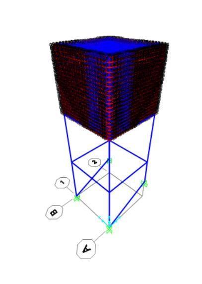
Figure 1: Displacementv/sGroundslopingindegreesin zoneIIforemptytankcondition
Table 6: BaseShearinzoneIIforemptytankcondition
B. Full Tank Condition
This analysis focuses on evaluating the seismic response of the water tank resting on levelled and sloped ground, with ground slopes ranging from 00 to 300 with 50 intervals, under full tank condition, with the water tank assumedtohavea fixed base.For the analysisofthe full tank condition in Zone II, both impulsive and convective pressuresareconsidered.
The modal parameters, displacements at different heights, and base shear for various ground sloping are presentedbelow.
International Research Journal of Engineering and Technology (IRJET) e-ISSN: 2395-0056
Volume: 11 Issue: 03 | Mar 2024 www.irjet.net p-ISSN: 2395-0072
Table 7: ModalparametersinzoneIIforfulltank condition
Table 8:DisplacementsinzoneIIforfulltankcondition
Ground sloping in Degrees Displacements(mm)

Figure 2: Displacementv/sGroundslopingindegreesin zoneIIforfulltankcondition
Table 9: BaseShearinzoneIIforfulltankcondition
4.1.2 ANALYSIS OF WATER TANK IN ZONE III
A. Empty Tank Condition This analysis focuses on evaluating the seismic response of the water tank resting onlevelledandslopedground,withgroundslopesranging from 00 to 300 with 50 intervals, under empty tank condition,consideringthedeadloadofthestructure.
The Following factors are considered from relevant IS code,forseismicanalysisinzoneIII.
a.Zonefactor:0.16(Table2,IS1893(Part1):2016)
b.ImportanceFactor:1.5(Table1,IS1893(Part2):2014)
c. Response Reduction Factor: 4 (Table 2, IS1893(Part 2):2014)
Table 10: Displacements in zone III for empty tank condition
International Research Journal of Engineering and Technology (IRJET) e-ISSN: 2395-0056
Volume: 11 Issue: 03 | Mar 2024 www.irjet.net p-ISSN: 2395-0072

4: Displacementv/sGroundslopingindegreesin zoneIIIforemptytankcondition

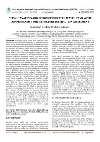
Figure 5: Deformedwatertankmodel
Table 11: BaseShearinzoneIIIforemptytankcondition
Table 12: DisplacementsinzoneIIIforfulltank condition
sloping in Degrees
B. Full Tank Condition
Thisanalysisfocusesonevaluatingtheseismicresponseof thewatertankrestingonlevelledandslopedground,with ground slopes ranging from 00 to 300 with 50 intervals, under full tank condition. For the analysis of the full tank condition in Zone III, both impulsive and convective pressures are considered. The modal parameters, displacementsatdifferentstaging heights, and baseshear forvariousgroundslopingarepresentedbelow.

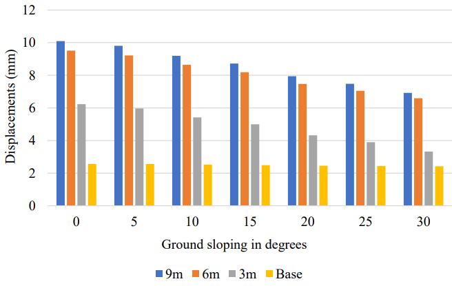
Figure 6: Displacementv/sGroundslopingindegreesin zoneIIIforfulltankcondition
Table 13: BaseShearinzoneIIIforfulltankcondition
From Table 4 to 13, and Figure 1 to 6, the following observations are made:
1. Displacements and Base Shear are higher in full tank condition due to the presence of hydrostatic pressure. This indicates that the water mass exerts additional seismicforcesonthestructure.
2. ThehigherBaseShearvaluesinZoneIIIindicateamore significant seismic force on the structure compared to ZoneII.
3. The increase in ground sloping from 00 to 300 with 50 intervals generally increases structural stiffness, resulting in higher natural frequencies, and reduced lateraldisplacementsinbothZoneIIandIII.
4. The distribution of mass influences the displacement patternsduringseismicevents.
International Research Journal of Engineering and Technology (IRJET) e-ISSN: 2395-0056
Volume: 11 Issue: 03 | Mar 2024 www.irjet.net p-ISSN: 2395-0072
5. Displacementsdecreaseasgroundslopeincreasesfrom 00 to300 forbothemptytankandfulltankconditions.A steeperslopinggroundmayleadtoincreasedstructural stiffness, reducing the flexibility of the tank and resultinginsmallerlateraldisplacements.
6. Increase in Base Shear is seen with an increase in ground slope from 00 to 300 for both empty tank and full tank conditions, indicating stability in lateral force distribution.
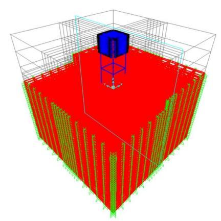
4.2 FLEXIBLE BASE ANALYSIS (SOIL-STRUCTURE INTERACTION)
The effects of Soil- Structure Interaction (SSI) on water tanks resting on levelled and sloped ground, considering factorssuchassoilcharacteristics,foundationdesign,and varyinggroundslopesfrom00 to300 with50 intervals.The structural foundation consists of an isolated square footingofdepth500mm,located1.5mbelowgroundlevel. Thesoilisaccuratelymodelled,extending10minwidthon bothsidesandreachingadepthof15m. The soil in the model is constrained with specific boundaryconditions:restraintsinthex-axiswithintheYZ plane, restraints in the y-axis within the XZ plane and fixity at the bottom of soil model. This involves dividing the modelled soil geometry into a grid or network of smallerelementstofacilitatenumericalanalysis.Response Spectrummethodofanalysisisperformed.
Table 14: SoilProperties(Swamisaran,2019)
i. Soft Soil Condition
Table 15: ModalParametersinzoneII(Softsoil)for emptytankcondition
Table 16: DisplacementsinzoneII(Softsoil)forempty tankcondition
4.2.1 ANALYSIS OF WATER TANK IN ZONE II FOR EMPTY TANK CONDITION
The seismic analysis of a water tank resting on levelled and sloped ground in seismic zones II, considering soft, medium, and hard soil conditions, the analysis focuses on theseismicresponseofthewatertankunderthecondition of an empty tank, considering the dead load of the structure.
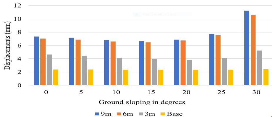
Figure 7: Displacementsv/sGroundslopingindegrees inzoneII(Softsoil)foremptytankcondition
Table 17: BaseShearinzoneII(Softsoil)foremptytank condition
International Research
Volume: 11 Issue: 03 | Mar 2024 www.irjet.net

Soil-StructureInteraction(SSI)modelofwater tankonslopedground
ii. Medium Soil Condition
Table 18: ModalParametersinzoneII(Mediumsoil)for emptytankcondition

Figure 9: Displacements v/s Ground sloping in degrees inzoneII(Mediumsoil)foremptytankcondition
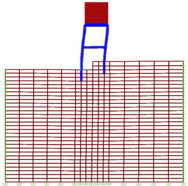
Table 19: DisplacementsinzoneII(Mediumsoil)for emptytankcondition
Figure 10: Deformedshapeofwatertankonsloped ground
Table 20: BaseShearinzoneII(Mediumsoil)forempty tankcondition
International Research Journal of Engineering and Technology (IRJET) e-ISSN: 2395-0056
Volume: 11 Issue: 03 | Mar 2024 www.irjet.net p-ISSN: 2395-0072
iii. Hard Soil Condition
Table 21: ModalparametersinzoneII(Hardsoil)for emptytankcondition
4.2.2 ANALYSIS OF WATER TANK IN ZONE III FOR EMPTY TANK CONDITION
i. Soft Soil Condition
Table 24: DisplacementsinzoneIII(Softsoil)forempty tankcondition
in Degrees
Table 22: DisplacementsinzoneII(Hardsoil)forempty tankcondition
Ground sloping in Degrees
Displacements(mm)
As the displacement values for 200and 300 ground slopes are exceeding the limiting value (H/500) which is 12mm (IITK-GSDMA,2007),Bracingsystemsareadoptedtolimit thedisplacementvaluesasperrelevantstandards.
Table 25: DisplacementsforX-bracings(300mmx 300mm)inzoneIII(Softsoil)foremptytankcondition
Ground sloping in Degrees
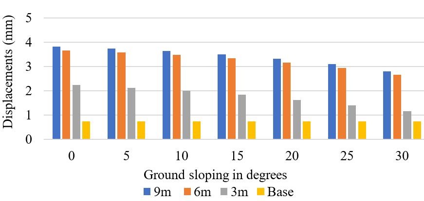
Figure 11: Displacementsv/sGroundslopingindegrees inzoneII(Hardsoil)foremptytankcondition
Table 23: BaseShearinzoneII(Hardsoil)foremptytank condition
Displacements(mm) at different height

Figure 12: Displacementsv/sGroundslopingindegrees inzoneIII(Softsoil)foremptytankcondition.
International Research Journal of Engineering and Technology (IRJET)
Volume: 11 Issue: 03 | Mar 2024 www.irjet.net p-ISSN: 2395-0072
Table 26: BaseShearinzoneIII(Softsoil)foremptytank condition
iii. Hard Soil Condition
Table 29: DisplacementsinzoneIII(Hardsoil)forempty tankcondition
Ground sloping in Degrees
Displacements(mm) at different
ii. Medium Soil Condition
Table 27: DisplacementsinzoneIII(Mediumsoil)for emptytankcondition
Ground sloping in Degrees
Displacements(mm) at different height

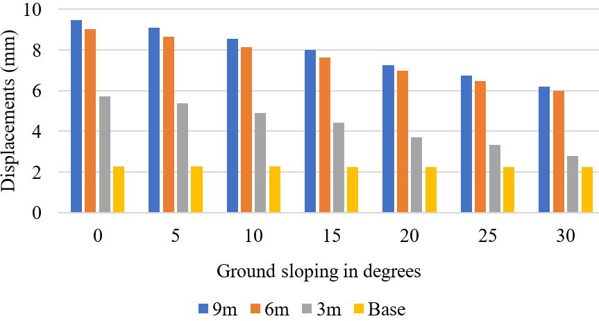
Figure 13: Displacementsv/sGroundslopingindegrees inzoneIII(mediumsoil)foremptytankcondition
Table 28: Base Shear in zone III (Medium soil) for empty tankcondition
Figure 14: Displacementsv/sGroundslopingindegrees inzoneIII(Hardsoil)foremptytankcondition
Table 30: BaseShearinzoneIII(Hardsoil)foremptytank condition
4.2.3 ANALYSIS OF WATER TANK IN ZONE II FOR FULL TANK CONDITION
The seismic analysis of a water tank resting on levelled and sloped ground in seismic zones II, considering soft, medium, and hard soil conditions, the analysis focuses on theseismicresponseofthewatertankunderthecondition of a full tank, considering both impulsive and convective pressures.
International Research Journal of
Volume: 11 Issue: 03 | Mar 2024 www.irjet.net
i. Soft Soil Condition
Table 31: ModalParametersinzoneII(Softsoil)forfull tankcondition
Table 32: DisplacementsinzoneII(Softsoil)forfull tankcondition
15: Displacementsv/sGroundslopingindegrees inzoneII(Softsoil)forfulltankcondition
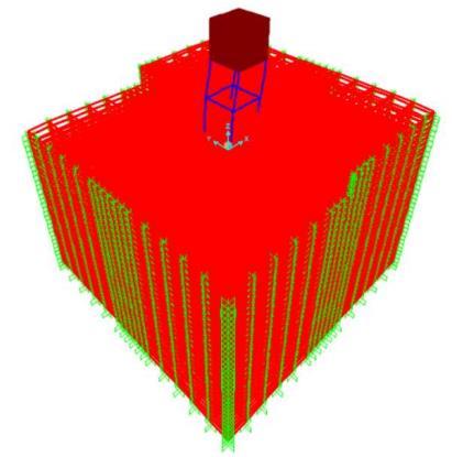
Table 33: BaseShearinzoneII(Softsoil)forfulltank condition
International Research Journal of Engineering and Technology (IRJET) e-ISSN: 2395-0056
Volume: 11 Issue: 03 | Mar 2024 www.irjet.net p-ISSN: 2395-0072
ii. Medium Soil Condition
Table 34: ModalParametersinzoneII(Mediumsoil)for fulltankcondition
iii. Hard Soil Condition
Table 37: ModalParametersinzoneII(Hardsoil)forfull tank
Table 35: DisplacementsinzoneII(Mediumsoil)forfull tankcondition
Ground sloping in Degrees
Displacements(mm) at different height
at different
Table 38: DisplacementsinzoneII(Hardsoil)forfulltank condition Ground sloping in Degrees
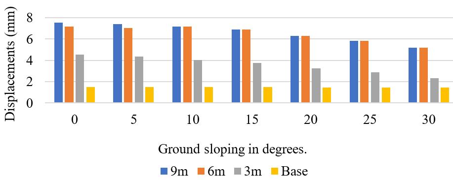
Figure 18: Displacementsv/sGroundslopingindegrees inzoneII(Mediumsoil)forfulltankcondition
Table 36: BaseShearinzoneII(Mediumsoil)forfulltank condition

Figure 19: Displacementsv/sGroundslopingindegrees inzoneII(Hardsoil)forfulltankcondition
Table 39: BaseShearinzoneII(Hardsoil)forfulltank condition
International Research Journal of Engineering and Technology (IRJET) e-ISSN: 2395-0056
Volume: 11 Issue: 03 | Mar 2024 www.irjet.net p-ISSN: 2395-0072
4.2.4 ANALYSIS FOR WATER TANK IN ZONE III FOR FULL TANK CONDITION
i. Soft Soil Condition
Table 40: DisplacementsinzoneIII(Softsoil)forfulltank condition
Ground sloping in Degrees
Asthedisplacementvaluesfor00 ,50and150 groundslopes areexceedingthelimitingvalues(H/500)whichis12mm (IIITK-GSDMA, 2007) Bracings systems are adopted to limitdisplacementvaluesasperrelevantstandards.
Table 41: DisplacementsforX-bracings(300mmx 300mm)inzoneIII(Softsoil)forfulltankcondition
Ground sloping in Degrees
at different height

Figure 21: WatertankmodelwithX-bracings(300mmx 300mm)inzoneIII(Softsoil)forfulltankcondition
Table 42: BaseShearinzoneIII(Softsoil)forfulltank condition Ground sloping in degrees Base Shear

Figure 20: Displacementsv/sGroundslopingindegrees inzoneIII(Softsoil)forfulltankcondition
ii. Medium Soil Condition
Table 43: DisplacementsinzoneIII(Mediumsoil)forfull tankcondition Ground
Degrees
Volume: 11 Issue: 03 | Mar 2024 www.irjet.net

Figure 22: Displacementsv/sGroundslopingindegrees inzoneIII(Mediumsoil)forfulltankcondition
Table 44: BaseShearinzoneIII(Mediumsoil)forfull tankcondition
iii. Hard Soil Condition
Table 45: DisplacementsinzoneIII(Hardsoil)forfull tankcondition
Ground
in Degrees

Figure 23: Displacementsv/sGroundslopingindegrees inzoneIII(Hardsoil)forfulltankcondition
Table 46: BaseShearinzoneIII(Hardsoil)forfulltank condition
5.CONCLUSION
1. Displacements and Base Shear are higher in full tank conditionduetothepresenceofhydrostaticpressure. This indicates that the water mass exerts additional seismicforcesonthestructure.
2. Inafulltankcondition,theeffectofslopinggroundon displacement is influenced by the additional mass of water.
3. The higher base shear values in Zone III indicate a more significant seismic force on the structure comparedtoZoneII.
4. The displacement values are higher in soft soil conditionsduetohigherflexibility,whencomparedto medium,andhardsoilconditions.
5. Theincreaseingroundslopingofelevatedwatertank from 00 to 300 with 50 intervals, increases structural stiffness, resulting in higher natural frequencies, and reducedlateraldisplacementsinbothZoneIIandIII.
6. In fixed based condition, displacements decrease as ground sloping increases from 00 to 300 for both empty tank and full tank conditions, suggests that a steeper sloping ground correlates with increased structural stiffness, resulting in reduced flexibility of the water tank and consequently causing smaller lateraldisplacements.
7. Base Shear values increase with sloping ground, suggesting increased resistance to seismic forces in fixedbasecondition.
8. Displacements and Base Shear are higher in flexible base (Soil-Structure interaction) condition due to effectofsoilflexibilitycomparedtofixedbase.
9. Due to Soil-Structure Interaction, the seismic analysis reveals an increase in frequency of the water tank with higher ground sloping in Zone II and III for both empty and full tank condition. This signifies a correspondingimprovementinstructuralstiffness.
10. The displacements of empty water tanks in seismic Zone II and III in soft soil, accounting for SoilStructure Interaction, reveals that displacements decrease up to 150 ground slopes, indicating a stiffer response to seismic forces. However, beyond 150 ground slopes, displacements increase, suggesting a
International Research Journal of Engineering and Technology (IRJET) e-ISSN: 2395-0056
Volume: 11 Issue: 03 | Mar 2024 www.irjet.net p-ISSN: 2395-0072
shift towards greater soil flexibility and larger deformations.
11. Decreaseindisplacementsofa full watertank onsoft soil with increasing ground slope is attributed to enhanced structure stiffness, providing resistance againstlateralmovements.
12. In the case of medium and hard soils, for both empty tank and full tank conditions, as the ground slope increases, decreasing tank displacements, is due to inclination offering a stabilizing effect, minimizing lateralmovementswithsupportingsoils.
13. ObserveddisplacementsinzoneIIIunderboth empty tank and full tank conditions, exceeding limiting values, indicating the need for strengthening measurestoenhancestructuralstiffness.Hence,useof structuralbracingsisrecommended.
REFERENCES
[1] “Analysis and design of substructures limit state design”,RevisedsecondeditionSwamiSaran(2019)
[2] Ayub Patel, Sourabh Dashore (2017), “Seismic analysis of elevated RCC water tanks having different capacities” , International Journal of Engineering Science InventionResearch&Development;Vol.IV,IssueVI.
[3] Chaithra M, Krishnamoorthy A, Naurin Nafisa P M (2017), “Analysis of Soil - Structure Interaction on ResponseofTanksFilledwithFluid”,InternationalJournal of Civil Engineering and Technology (IJCIET) Volume 8, Issue7.
[4] Deeksha Jain, Deepak Kumar Bandewar, Sachin Jat (2022), “Dynamic Analysis of Intze Tank on Sloped Ground” ,InternationalJournalforResearchinEngineering Application & Management (IJREAM) ISSN: 2454-9150 Vol-08,Issue-01.
[5] Dhotre Chandrakala (2015), “Analysis on Overhead Circular water tank for various bearing capacity with sloping ground”, International Journal of Scientific & EngineeringResearch,Volume6,Issue5.
[6] GauravSengar,AnilRajpoot(2022),“DesignAnalysis and Comparison of Over Head Water Tank for Different Wind Speed and Seismic Zones as Per Indian Standard Codes”, International Journal of Research Publication and Reviews,Vol3,no9,pp1331-1337.
[7] Hariram Rimal, Piyush Pradhan, Dipendra Gautam, and Rajesh Rupakhety (2023), “Seismic Fragility of Aging Elevated Water Tank with Smooth Bars Considering Soil StructureInteraction”,Buildings2023,13,4(MDPI).
[8] Housner G W (1963),” The Dynamic Behavior of Water Tanks”, Bulletin of the Seismological society of America,53(2),381-387.
[9] IITK-GSDMA(2007),“Guidelinesforseismicdesignof liquid storage tanks”, National Information Centre for EarthquakeEngineering,IITKanpur.
[10] I.R. Saudagar, A.N. Shaikh (2019), “Study on Comparison Analysis of Circular and Intze Water Tank on Sloping Ground”, International Research Journal of Engineering and Technology (IRJET) e-ISSN: 2395-0056 Volume:06Issue:10.
[11] IS:3370 (Part-I) – 1965 code of practice for concrete structures for the storage of liquids. (General requirements).
[12] IS 1893 (Part 2): 2014 – Criteria for earthquake resistantdesignofstructures.(Liquidretainingtanks).
[13] IS 1893 (Part 1): 2016 – Criteria for earthquake Resistant Design of structures. (General provisions and buildings).
[14] JayadeepK.S, ThejaswiniR.M,L Govindaraju(2022), “A Study on The Seismic Response of Elevated Water Tank”, International Research Journal of Engineering and Technology (IRJET) e-ISSN: 2395-0056 Volume: 09 Issue: 03.
[15] Martin Sivy, Milos Musil, Ondrej Chlebo and Rene Havelka (2017), “Sloshing effects in tanks containing liquid”,MATECWebofConferences107.
[16] MeghaRachelPhilipandMinuAntony(2020),“Effect of Sloshing in Elevated Water Tank on Levelled and Sloping Ground”, International Research Journal of Engineering and Technology (IRJET) e-ISSN: 2395-0056 Volume:07Issue:06.
[17] Mohan M. Vaghjiyani, and Pravin L. Hirani (2018), “Seismic Analysis of Elevated Water Tank on Different Sloping Angle of Ground with Different Height and Capacity”, International Research Journal of Engineering and Technology (IRJET) e-ISSN: 2395-0056 Volume: 05 Issue:10.
[18] Mor Vyankatesh K, and More Varsha T (2017), “Comparative Study on Dynamic Analysis of Elevated WaterTankFrameStagingandConcreteShaftSupported” , IOSR Journal of Mechanical and Civil Engineering (IOSRJMCE)e-ISSN:2278-1684,P-ISSN:2320-334X,Volume14, Issue1Ver.I.
[19] M. Sai Ramya and J. Sandhya Rani (2019), “Seismic analysis of RC elevated rectangular water tank using various staging patterns”, CVR journal of science and technology,Volume17.
[20] Nishigandha R.Patil , and Dr. R. S. Talikoti (2015), “Seismic Analysis of Elevated Water Tank”, International
International Research Journal of Engineering and Technology (IRJET) e-ISSN: 2395-0056
Volume: 11 Issue: 03 | Mar 2024 www.irjet.net p-ISSN: 2395-0072
Journal of Civil and Structural Engineering Research ISSN 2348-7607Vol.3,Issue1,pp:(90-94).
[21] S. A. Halkude, and A. A. Perampalli (2013), “Analysis ofWaterTankonSlopingGround” ,InternationalJournalof EngineeringandInnovativeTechnology(IJEIT),Volume3, Issue5.
[22] Sagar T Mane, and Prashant M Kulkarni (2019), “Comparative Analysis of Circular and Rectangular Elevated Water Storage Tank Using Different Types of Bracing System”, Journal of Structural Technology e-ISSN: 2581-950Volume4Issue3.
[23] Sagar T. Mane and prof. Prashanth M. Kulkarni (2019), “Time history analysis of circular and rectangular elevated water storage tank using Baffle walls” , International Journal of Engineering and Management Research,volume-9,issue–4.
[24] Sayed Habiburahman Haqbin, Chintan. D. Patel and Bansal. R. Patel (2017), “Seismic Analysis of RC Elevated RectangularWaterTank usingIs 1893 (Part2):2006Draft Code”,InternationalJournalofAdvanceResearch.
[25] Suyash Nerkar, and Chittaranjan Nayak (2016), “Seismic behaviour of elevated storage reservoir by finite element method”, International Journal of Advanced Technology in Engineering and Science Volume No.4, SpecialIssueNo.1.
[26] Swathi C. Naik and M.S. Bhandiwad (2016), “Seismic analysis and optimization of a rectangular elevated water tank”, Bonfring international journal of man machine interface,vol.4,SpecialIssue.
[27] ThoratYogesh,KadamYogesh,KuteSagarandKashid Sanchit (2017), “Analysis of Water Tank on Sloping Ground”, International Journal of Engineering Sciences & Management.
© 2024, IRJET | Impact Factor value: 8.226 | ISO 9001:2008
|