
International Research Journal of Engineering and Technology (IRJET) e-ISSN: 2395-0056
Volume: 11 Issue: 03 | Mar 2024 www.irjet.net p-ISSN: 2395-0072
International Research Journal of Engineering and Technology (IRJET) e-ISSN: 2395-0056
Volume: 11 Issue: 03 | Mar 2024 www.irjet.net p-ISSN: 2395-0072
Devaprasath A1 , Gowtham S1 , Hariharan V1, Sivakumar S2
1Student, Department of Mechanical Engineering, Kumaraguru College of Technology, Tamil Nadu, India. 2Assistant Professor II, Department of Mechanical Engineering, Kumaraguru College of Technology, Tamil Nadu, India.
Abstract – Thesearchforimprovingheattransferandfluid mixing efficiency in diverse engineering applications has prompted the investigation of novel vortex generator geometries and combinations. This study examines the thermohydraulic performance of a new ramping expansion channelincorporatedcurveddeltawinglet vortexgenerator. The goal of the curved delta winglet vortex generator is to minimize pressure loss while increasing convective heat transferandcreatingvortices.Theuseofarampedexpansion channelisintendedtoregulatetheflowfieldandenhancethe capacity for heat transmission. The study methodically investigates the effects of ramp angle, winglet height, and geometrical factors on the system's thermohydraulic performance.
Key Words: Heat transfer, vortex generator, ramped expansionchannel,rampangle.
Theutilizationofvortexgeneratorsinreal-timehasbeen madepossiblebyrecentsuccessfulinventions,research,and testing aimed at improving the effect of heat transmission.By creating vortices in the boundary layer, delta winglet vortex generators have traditionally shown themselves to be effective in enhancing convective heat transfer.Butmorerecently,developmentshaveaccelerated the shift to curved versions, leveraging the advantages of curved geometries to maximize vorticity production and flow management. Meanwhile, the addition of a ramped expansionchannelgivestheflowrouteanewdimensionand improves mixing and heat transmission properties. Comprehendingthecomplexitiesofheattransmissionand fluid movement in this unique arrangement is crucial for improvingthermalengineeringtechniques.Theknowledge gained from this study may be applied to the design and improvementofair-coolingsystems,heatexchangers,and other thermal management equipment, leading to the creation of more sustainable and energy-efficient engineeringsolutions.
Separated flows are difficult to understand because of their unpredictable nature. To better understand these
instabilitiesand,tosomeextent,reducetheunpredictability, researchers have been experimenting with a variety of shapes,includingrib,fence,bluffbodywithasplitterplate, abruptly expanding pipes, ramping duct, and cavities. Becauseofitsonesetseparationpoint,therampedexpansion channelprovedtobethemostpopularofall.Therearethree mainareasthatmakeuptheflowwake:theshearlayerarea, the separation bubble or recirculation zone, and the reattachment zone. These divisions are based on the importantflowcharacteristicsinaplanarrampinggeometry thathavebeenstudiedbypreviousresearchers.Duetothe unfavorable pressure gradient that forms into a thin boundary layer, the basic features of a ramped expansion flow start with an angular momentum in the flow. The turbulentstructuresinsidetheboundarylayermergeasthe flow moves downstream, expanding the boundary layer's area.Theterm"layerregion" referstothisarea wherethe boundarylayerformsandexpands.Inthespacebetweenthe shear layer and the nearby wall, this flow results in lowvelocityrecirculation.Therecirculationzoneoftheramping geometry produces a primary vortex in the center and a secondary vortex adjacent to the corner. When the shear layer eventually swings down towards the wall, the reattachment point is where the fluid's advantageous pressuregradienthitsthewallataspecificlocation.
To provide a safety buffer between the airspeed and stall speed,vortexgeneratorsaretoolsthathelplowerthestall speed. By increasing the flow's turbulent nature and decreasing the creation of boundary layers, vortex generatorsaidinimprovingheattransferperformance.Ina channel,thestrongturbulentflowofthemediumdecreases the development of boundary layers and increases heat transmission. Based on their features and usage patterns, vortex generators may be categorized. Both passive and active vortex generators are those. Using a certain aerodynamicsurfaceshape,passivevortexgeneratorsmay producerollingorlongitudinalverticeswithouttheneedfor outsidepowersources.Deltawinglet(DW)andDeltawinglet pair(DWP)arethemostutilizedconfigurations.Awingletis createdwhenthevortexgeneratorshavedistinctanglesof attack from one another, whereas a wing is defined as geometrypositionedperpendiculartothedirectionofflow.
International Research Journal of Engineering and Technology (IRJET) e-ISSN: 2395-0056
Volume: 11 Issue: 03 | Mar 2024 www.irjet.net p-ISSN: 2395-0072
Scientificallysounddiscoveriesareproducedbystudyusingasoundapproach.Theprocedureismadeeasy,efficient,and manageablebythecomprehensivestrategyitoffers,whichalsoaidsinkeepingresearchersoncourse.Findingtrustworthyand accuratedata,comingtoinsightfulconclusions,andaddingtothebodyofknowledgeareallhamperedbyapoorlydefined researchtechnique.
Design Calculations
Fabrication
Modelling
Observation and Calculation
3. Design Calculation
Settingupanexperimentisacrucialstepincarryingouta study. The experiment involves designing the vortex generatorsandthesuddenexpansionrampingflowductby consultingreferencesfromdifferentjournalsandmodifying theirspecificationsaccordingtotheneeds.Thefinaloutput variesdependingonthestability,capacity,performance,and durabilityofthematerialsutilizedintheprocess.
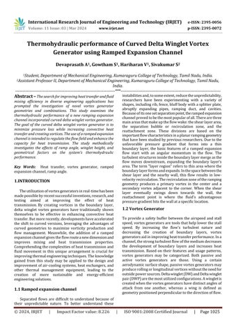
3.1. Ramped Expansion channel dimensions
Comic Section
dimensionsareinmm.
Fig. 2. ComicSection
Material Outsourcing
Resultsand Report Generation
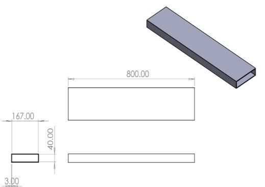
Testing Section
dimensionsareinmm.
3. TestingSection
Ramped duct angle = 450
International Research Journal of Engineering and Technology (IRJET) e-ISSN: 2395-0056
Volume: 11 Issue: 03 | Mar 2024 www.irjet.net p-ISSN: 2395-0072
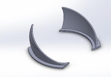
3.2. Delta Vortex Generator Dimensions
Height=27mm
Length=45mm
Radius=23mm
Thickness=1mm
Material=CurableAlumina
4. Component Specification
S.No. MATERIALS
DIMENSION
1 CopperPlate 1000x167x2.5mm
4 Plexiglass(acrylic)Sheet 1800×167×3mm
5 Thermocouple(T-type) ø=0.2mm(Accuracy =0.02°C)
6 Nylon 1kg
7 RockWool 2sq.m.
8 Blower 200CubicFeetPer Minute
9 Heater (stainlesssteel) 1000mm×200mm
10 VariacController 0-240V(singlephase)
11 DataAcquisitionSystem 18channels
12 Thermometer Accuracy=±0.02°C
Table.1. ComponentSpecification
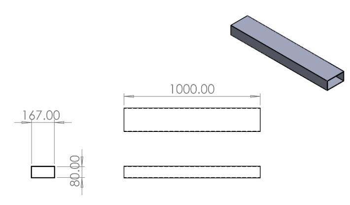
5. Experimental Setup
Therock-woolinsulationbedispositionedatthebottom ofthetestsection,withtheheateremployedinbetweenthe copperplates.Weutilizeanairblowerontheothersideof theentrancetochangethedirectionoftheairflow.Variac controllers are used to regulate both the heater and the blower'svoltageinput.Plexisheetisusedtoconstructthe testandcomicsections,whicharejoinedtoformachannel thatisenclosedonallsidesexcepttheinputandoutflow.We employ18"T-type"thermocouples,whichareaffixedtothe copperplate'sbottominadirectionparalleltothestreamto
measure the temperature of the plate.A data acquisition system (DAQ) is then used to measure the readings from thesethermocouplesanddisplaythecorrespondingoutputs. The mass flow rate of air at the comic section's input is measured with a vane anemometer. Pressure transducers areusedatthechannel'sentranceandoutflowtomeasure thepressuredecrease.
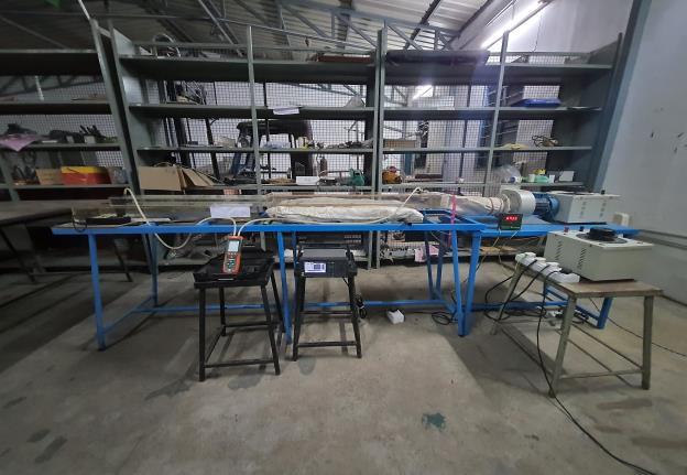
Fig.6. ExperimentalSetup
In this experimentation, we position the Curved Delta VortexGeneratorwithhigherleadingedgeinbothcommon flowupandcommonflowdownconfigurationandobserve theirheattransmissioncapabilitiesbyvaryingthevelocityof thefluidfordifferentattackangleofthevortexgenerator.
CommonFlowUp(CFU)configurationofCurved DeltaVortexGenerator – [Allanglecomparison]
FrictionFactor,f=(2*ΔP*Dh)/(ρ*V2*L)
ReynoldsNumber,Re=(ρ*V*Dh)/µ
The relation shows that the friction factor decreasesasthevelocityofthefluidincreasesand theReynolds numberincreasesasthevelocity of thefluidincreases.
International Research Journal of Engineering and Technology (IRJET) e-ISSN: 2395-0056
Volume: 11 Issue: 03 | Mar 2024 www.irjet.net p-ISSN: 2395-0072
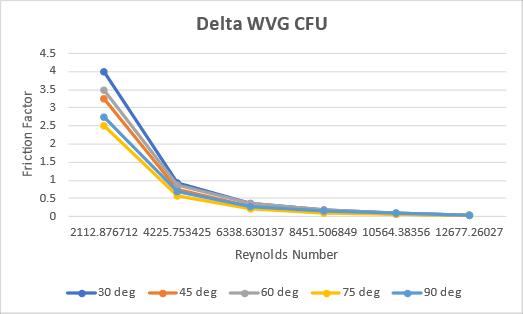
Fig.7. FrictionfactorvsReynoldsnumber
Nusseltnumber,Nu=(h*Dh)/k
ReynoldsNumber,Re=(ρ*V*Dh)/µ
The Nusselt number is the function of Reynolds numberraisedtothecertainpoweralongwiththe Prandtlnumber.
Laminar External flow, Nu ≈ 0.664 * (Re^0.5) * (Pr^0.33)
Turbulent External flow, Nu ≈ 0.037 * (Re^0.8) * (Pr^0.3)
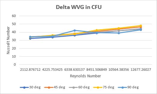
Fig.8. NusseltnumbervsReynoldsnumber
The above graph(Fig.8.)indicates the relation betweenNusseltnumberandReynoldsnumberforvarious attackangles.
Boththeabovegraphs, (Fig.7.)and (Fig.8.) implies thattheattackangle750 showsthe betterthermohydraulic performancefactorwithgreaterheattransmissionrateand lower pressure loss compared to all other attack angles beingpositionedinthecommonflowupconfiguration
Attack Angle = 750
Table.2. DataobtainedforAttackangle750 inCFU
Common Flow Down (CFD) configuration of Curved Delta Vortex Generator – [All angle comparison]
Analyzingthecommonflowdownperformanceof theCurvedDeltaVortexGeneratorintheramped expansion channel resulted in the following outcomes.
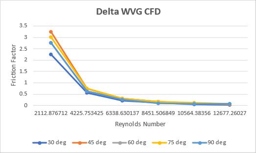
Fig.9. FrictionfactorvsReynoldsnumber
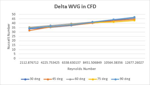
Fig.10. NusseltnumbervsReynoldsnumber
International Research Journal of Engineering and Technology (IRJET) e-ISSN: 2395-0056
Volume: 11 Issue: 03 | Mar 2024 www.irjet.net p-ISSN: 2395-0072
Both the above graphs, (Fig.9.) and (Fig.10.) implies that the attack angle 300 shows the better thermohydraulic performance factor with greater heat transmissionrateandlowerpressurelosscomparedtoall other attack angles being positioned in the common flow downconfiguration.
2.0
Table.3. DataobtainedforAttackangle300 inCFD
7. CONCLUSIONS
Hydro-thermalcharacteristicsoftherampedexpansion channelinunderprocess.Furtherthechannelwithacurved delta winglet vortex generator is made using Curable Aluminafilamentandplacedinthechannel.BothCommon flowupandCommonflowdownconfigurationswithvarying angles of attacks are experimented with. The overall performance of the vortex generator is evaluated with Nu numberandFrictionfactor.Thebelowlistedconfiguration showsthegreaterperformancecharacteristicsintheramped expansionchannelusingCurvedDeltaVortexGenerator.
guidance,andalsoforprovidingusallthenecessaryfacilities required for carrying out this project work. We are very grateful to our respected Head of the Department, MechanicalEngineering, Dr.C.Velmurugan forhisconstant and continuous motivation, review, and cooperation throughout this project work. We wish to record our profound happiness and gratitude to our Project Coordinator Dr. K. M. Senthilkumar, DR. K. Krishnamoorthi, DR. S. Sivakumar andProjectGuide Mr. S. Sivakumar for their constant and continuous effort, guidance,andvaluabletime.Oursincereandheartythanksto allthefacultymembersandstaffofMechanicalEngineering Departmentfortheirwellwishes,timelyhelpandsupport rendered to us for doing this final year design and fabricationprojectwork.Weareverygreatlyindebtedtoour family,relativesandourallfriendswithoutwhomourlife wouldnothavebeenshapedtothislevel.
[1] Esmaeilzadeh,N.Amanifard,andH.M.Deylami,“In ordertomaximizeflowcharacteristicsandenhance heattransferinaheatexchanger,acomparisonof straightandcurvedtrapezoidallongitudinalvortex generatorswasconducted,” Appl. Therm. Eng.,vol. 125,pp.1414–1425,2017.
[2] Armaly, B., Durst, F., Pereira, J., & Schönung, B. Experimental and theoretical investigation of backward-facing step flow. Journal of Fluid Mechanics,127, 473-496. doi:10.1017/S0022112083002839
[3] W.Hu,L.Wang,Y.Guan,andW.Hu,“Theimpactof wingletvortexgeneratorshapeona circulartube bank fin heat exchanger's thermal-hydrodynamic performance,” Heat Mass Transf. und Stoffuebertragung, vol. 53, no. 9, pp. 2961–2973, 2017.
[4] M.F.MdSalleh,H.A.Mohammed,andM.A.Wahid, “Thermal and hydraulic characteristics of trapezoidal winglet across fin-and-tube heat exchanger(FTHE),” Appl. Therm. Eng.,vol.149,no. November2018,pp.1379–1393,2019.
Table.4 Endresultoftheaboveexperimentalstudy
ACKNOWLEDGEMENT
We wholeheartedly thank our Chairman Dr. B. K Krishnaraj Vanavarayar, our Correspondent Thiru. M.Balasubramanium, our Joint Correspondent Thiru. Shankar Vanavarayar, our advisor Dr. V. Manivel muralidaran for providing us with the required infrastructure at Kumaraguru College of Technology. We express our gratitude to our beloved Principal Dr. D. Saravanan, for his invaluable support, motivation, and
[5] S. K. Sarangi, D. P. Mishra, H. Ramachandran, N. Anand, V. Masih, and L. S. Brar, “Examining and refining the small heat exchanger's curved trapezoidal winglet geometry,” Appl. Therm. Eng., vol.182,no.September2020,p.116088,2021.
[6] J. Carpio and A. Valencia, “Enhancement of heat transferusinglongitudinalvortexgeneratorsinflattubecompactheatexchangers,” Int. Commun. Heat MassTransf.,vol.120,no.xxxx,p.105035,2021.
International Research Journal of Engineering and Technology (IRJET) e-ISSN: 2395-0056
Volume: 11 Issue: 03 | Mar 2024 www.irjet.net p-ISSN: 2395-0072
[7] Tsay,YL.,Chang,T.&Cheng,J.Enhancementofheat transferforbackward-facingstepflowinachannel with the placement of baffles on the channel wall. Acta Mechanica 174, 63–76 (2005). https://doi.org/10.1007/s00707-004-0147-5
[8] Abbott,D.E.,andKline,S.J.(September1,1962)." ExaminingSubsonicTurbulentFlowThroughSingle andDoubleBackwardFacingStepsExperimentally." ASME. J. Basic Eng. September 1962; 84(3): 317–325.https://doi.org/10.1115/1.3657313
[9] Kanna,P.R.,andDas,M.K.(January25,2006)."A two-dimensional LaminarInflexible Wall JetFlow Under Backward-Facing Step: A Numerical Simulation."ASME. J. Fluids Eng.September2006; 128(5): 1023–1035.https://doi.org/10.1115/1.2243298
2024, IRJET | Impact Factor value: 8.226 |