
Volume: 11 Issue: 03 | Mar 2024 www.irjet.net
Volume: 11 Issue: 03 | Mar 2024 www.irjet.net
Sajad Ahmad Wani1, Ibraheem1, Shahida Khatoon1, Mohammad Shahid2
1Department of Electrical Engineering, Faculty of Engineering and Technology, Jamia Millia Islamia, New Delhi, India
2Department of Electrical Engineering, Galgotia College of Engineering and Technology, Greater Noida, India
Abstract-Smart wheelchair systems have gained significant attention in recent times because of their potential in enhancing mobility and independence for people with disabilities. One of the critical components of a smart wheelchair system is the DC motor used for propulsion. The speed regulation of DC motor used in smart wheelchair system is a crucial aspect of the overall efficiency of the system. In this paper, we compare the performance of various controllers for the speed regulation of a DC motor used in a smart wheelchair system. The different controllers used in this study are Proportional-Integral-Derivative (PID) controller, Fuzzy logic controller (FLC), and Particle Swarm-optimized PID controller. A systematic simulation procedure was followed to compare the performance of each controller. The results of the study indicate that the Particle SwarmOptimizedPIDcontrollerprovidesthebestperformancein terms of speed control, with better tracking accuracy and fasterresponsetime.Thestudyprovidesacomprehensive comparison of different controller types for the speed regulation of DC motor in a smart wheelchair system, whichcanhelpresearchersandpractitionerstochoosean appropriatecontrollerfortheirspecificapplications.
Key Words: DC motor, Speed control, Smart wheelchair system, Proportional-Integral-Derivative (PID) controller, Fuzzy logic controller (FLC), Particle Swarm Optimization (PSO).
With time a lot of machines and devices have been designed and developed for the betterment of the human kind but the invention of the Smart wheelchair is a most important one. Smart, electrically powered wheelchairs have been identified as a most important tool for users suffering from mobility impairment and cognitive disabilities.So,thestudyofthesetypesofwheelchairshas been recognized as an important task towards the betterment of the society [1]. The speed regulation of the DC motor is crucial for the overall performance of the smart wheelchair system, as it directly affects the user's safety, comfort, and efficiency of the system. Several control and optimization techniques have been presented in the literature for the speed regulation of the DC motor, such as the Proportional-Integral-Derivative (PID)
2395-0072
controller, Fuzzy logic controller (FLC), Model predictive controller (MPC), Particle swarm optimization (PSO) and Ant-Colony optimization (ACO) [4]. This research work aims to compare the performance and efficiency of the threecontrollerdesignstrategiesforthespeedregulation oftheDCmotorusedinasmartwheelchairsystem.These strategies are Proportional-Integral-Derivative (PID) controller,Fuzzylogiccontroller(FLC)andPSO-Optimized PID controller. A systematic simulation procedure was followed to evaluate the working efficiency of each controller in terms of tracking accuracy, response time, andstability.Theresultsofthestudycanprovidevaluable insightsinto the selection of anappropriate controller for the speed regulation of DC motor in a smart wheelchair system.
Accurateandefficientcontroliscriticalineverysystemor process.Thisisonlypossiblebecauseofthecompensation provided by different controllers. Because of the low cost andeasytocontrol,DCmotorsarewidelyused inprocess industries,robots,wheelchairsandinothersmartdevices. Control systems practically used in day today lives suffer from a lot of disabilities and problems like undesirable overshoot,vibrations,andlarge-settlingtimeandstability issues. Real world processes and systems are inaccurate, non-linearandin-efficientduetowhichalotofcontrollers are used to compensate these irregularities [9]. Classical controllerslikePIDcontrollersgenerallyareineffectivein some cases due to which more advanced strategies like Fuzzy logic, Artificial Neural Network (ANN) technique and other optimization techniques like particle-swarmoptimization (PSO), Genetic-algorithm (GA), Ant-ColonyOptimization (ACO), Simulated-annealing (SA) etc. are used. All these techniques are effective and interesting techniques used in a lot of control problems and processes.
In this paper our main attention is on Proportionalintegral-derivative (PID) controller, Fuzzy logic controller (FLC) and PSO-optimized PID controller The focus of this research paper is to present a simple and efficient controllerforthespeedcontrol oftheDCmotor usedin a International Research Journal of Engineering and Technology (IRJET) e-ISSN:2395-0056
International Research Journal of Engineering and Technology (IRJET) e-ISSN:2395-0056
Volume: 11 Issue: 03 | Mar 2024 www.irjet.net p-ISSN:2395-0072
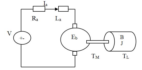
wheelchair system. Kinematical model of the motor is madeintermsofthespeedandangle.MATLAB/SIMULINK is then used to formulate the required Kinematical model and the different characteristics are studied by using proportional-integral-derivative (PID), Fuzzy logic Controller and particle-swarm optimized PID controller. Figure1depictstheschematicblockdiagramofDCmotor with all necessary hardware components like controller, powersupply,motordriverandwheelchair.
The design of efficient and reliable motor drives is a very crucial aspect in various processes and applications used in industries, factories, workshops and robotics. DC motors are commonly used in many industrial purposes because of their simplicity, high efficiency, and controllability. Speed control of a DC motor is an importantaspectofmotorcontrol,asitdirectlyaffectsthe system'sresponsetime,stability,andenergyconsumption. Huma khan, Shahida Khatoon et al. [2] developed a simplified model of motor using controllers such as PI , PID and LQR design strategy. In this paper LQR yields a better and efficient performance compared to PI and PID controllers. Soft-computing techniques like Fuzzy logic playacrucialroleinvelocitycontrolofDCmotors.Umesh KumarBansaletal.[3]presentedaworkonspeedcontrol ofDCmotorusingFuzzy-PIDcontroller.Heresteadystate characteristics and various other characteristics like torque-speedandtorque-currentcharacteristicsoftheDC motor utilizing PID-Fuzzy controller are thoroughly studied.RekhaKushwahet al.[5],K.Premkumaretal.[6] and S. Ushakumari[8] suggested a Fuzzy logic and an Adaptive Neuro-fuzzy approach to regulate the speed of brushless DC motor drive. The proposed strategy is compared with other techniques and various system parameters like Peak overshoot, Rise time, Delay time, Recovery time and Steady state characteristics has been noted and compared. Modeling and analysis of PMDC motor is done by Pragesen Pillay [9] and M.A.Jabbar [14]. Heremoreattentionispaidonsignaldynamicsandmotor torque characteristics. The simulation model is prepared in State Space and at every instance during on and off positionstheresultingCurrentandTorqueoscillationsare measured. Optimization techniques like PSO, ANN, ACO plays an important role in optimization of different parametersinaprocessorplant.Inthisresearchworkwe usedPSOcontroltechniquetooptimizetheparametersof PID control strategy to enhance the speed control characteristics. Particle Swarm Optimization (PSO) is a computationalstochasticoptimizationtechniquebasedon natureinspiredintelligentbehaviorofsomeanimals,birds andinsectslikebird-flocks,antcoloniesandfishschooling. It is a swarm based optimization originally formulated by Eberhart and kennedy [10]. Ruchi V. Jain et al. [12] presented PID and Fractional order PID controllers using PSOtocomparethespeedofDCmotor.Hereitwasshown
that Fractional order PID technique is more robust and efficientcomparedtonormalPIDcontroller.
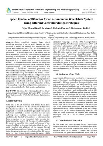
DC motors with permanent magnet use Commutator and other components like Brushes to achieve the commutation. But in case of brush-less motor, Hall Effect sensors are used to get the required mechanical commutation.InBLDCmotors,statorconsistsofacoiland therotorisapermanentmagnet.Thestatorcoilproduces the required magnetic field that interacts with the rotor magnetic field to give the rotor a resultant rotation. The equivalent electromechanical circuit diagram of DC motor canbedescribedbythecircuitasshowninfigure1,where La and Ra is the equivalent Inductance and Resistance of the DC motor coil respectively. Let the Torque produced by the motor be T and terminal voltage be V. By using Kirchhoff’s and Newtonian Laws the equations governing thesystemareasunder[14]:
ByconvertingtheaboveequationsintoequivalentLaplace transformation and solving these equations we get the followingtransferfunctionsasshownbelow:
International Research Journal of Engineering and Technology (IRJET) e-ISSN:2395-0056
Volume: 11 Issue: 03 | Mar 2024 www.irjet.net p-ISSN:2395-0072
G1(s)= = (9)
G2(s)= = (10)
Where, V is the given applied voltage, is the rotor speed,i(t)isthearmaturecurrent,Eb isthebackemf,Tis the torque, Kt is the motor time constant, R is the resistance,Listheinductance,JistheInertiacoefficient,B istheviscouscoefficientofmotor.Theotherspecifications ofthemotoraresummarizedinthetable1
Table 1 12VDCMotorSpecifications
Inductance 0.50
Inertia constant 0.02 Kg-m2
Viscous constant 0.10 Nm-sec
Themethodologyfollowedinthisstudyforcomparingthe performance of different controller design strategies for the speed regulation of a DC motor used in a smart wheelchairsystemisoutlinedbelow:
(a) System setup: A prototype smart wheelchair system with a DC motor was used for the study. The system's specifications, including the motor's voltage rating, currentrating,andspeedrange,werenoted.
(b)Controlsystemdesign:Thethreedifferentcontrollers, i.e.,PIDcontroller,FLC,and PSO-OptimizedPIDcontroller weredesignedandimplementedusingMATLAB/Simulink. The design parameters for each controller, such as gains, rules, and other parameters, were set based on the literaturereviewandsimulationresults.
(c) Data analysis: The collected data was analyzed to evaluate the performance of each controller in terms of tracking accuracy, response time, and stability. The
performance metrics were calculated based on the error between the desired and actual speed, the settling time, andtheovershoot.
The above methodology was followed for each controller, and the results were compared to evaluate the performanceofdifferentcontrollers.Thestudyprovidesa comprehensivecomparisonofdifferentcontrollersforthe speed control of a DC motor used in a smart wheelchair system, which can help researchers and practitioners to select an appropriate controller for their specific applications.
This Controller is considered as one of the simple and robust controller and it works on a feedback strategy to controlthegivenPlantorProcess.ItisacombinationofP, IandDcontroller.Itisaclassicalcontrollerwhichisused to change the motor velocity by taking different values of Kp,Ki andKd.Thesummationofallthesecomponentsgives the required signal that is utilized to get the optimum efficiencyofthesystem.ThebasicideabehindusingaPID controller for speed control of a DC motor is to use feedback from the motor's actual speed to adapt the control signal sent to the motor. The Proportional, Integral,andDerivative(PID)termsareusedtoadjustthe controlsignalbasedonthedifferencebetweenthedesired speedandtheactualspeed.Thisallowsforprecisecontrol of the motor's speed and ensures that it remains at the desired speed, even when external factors such as load changes or disturbances are present [12][13]. For the optimum result, the different controllers are tuned accordingly based on the given transfer function. The activatingsignalobtainedbythePIDcontrollerisgivenby thefollowingdynamicequation:
C(t)=Kpe(t)+Ki∫ +Kd (11)
Transfer function of the above controller in‘s’ domain can besimplifiedas:
C(s)=Kp +Ki/s+Kd s (12)
DesigningaPID(Proportional-Integral-Derivative) controllerforthespeedcontrolofaDCmotorusedina smartwheelchairsysteminvolvesthefollowingsteps:
(a) DCmotormodeling:Developamathematicalmodelof the motor that represents its dynamic behavior. This canbedonethroughexperimentsorsimulations.
(b) System identification: Determine the parameters of the DC motor model, such as the resistance, inductance, and back-emf constant, through experimentaltests.
(c) Controller design:DesignthePIDcontrollerusing the mathematical model of the DC motor. The PID
Volume: 11 Issue: 03 | Mar 2024 www.irjet.net p-ISSN:2395-0072
controllerismadeofthreecomponents:proportional, integral, and derivative. The proportional term provides a control output proportional to the error betweenthedesiredspeedandtheactualspeedofthe motor. The integral term integrates the error over time to reduce steady-state errors. The derivative term anticipates the future behavior of the system based on its current rate of change and helps to dampenoscillations.
(d) Parameter tuning: Determine the values of the PID controller gains (Kp, Ki, Kd) to get the desired performance. The tuning can be done through simulationsorexperimentaltrials.
(e) Implementation and testing: Implement the PID controllerontheDCmotorusingamicrocontrolleror a dedicated motor controller. Test the system under various operating conditions to evaluate its efficiency in terms of tracking accuracy, response time, and stability.
(f) Performance evaluation: Collect data on the system's performanceandevaluatetheperformanceofthePID controllerincomparisontoothercontrollertypes,
Fuzzy logic approach mimics the human behavior takes into consideration all the required formalities that are absent in other conventional controllers like PID controller. Fuzzy logic is a very effective and efficient technique in solving different control problems. The design of an FLC used in a smart wheelchair system involves a good understanding of the system's dynamics, controller theory, and tuning methods. The FLC is a popular controller that can handle uncertainties and nonlinearities in the system, making it suitable for regulating the speed of the motor. Fuzzy logic Controller for the speed control of a DC motor used in a smart wheelchairsysteminvolvesthefollowingsteps:
(a) DCmotormodeling:Developamathematicalmodelof the motor that represents its dynamic behavior. This canbedonethroughexperimentsorsimulations.
(b) System-identification: Determine the parameters of the DC motor model, such as the resistance, inductance, and back-emf constant, through experimentaltests.
(c) Fuzzyrulebasedesign:Definethefuzzysetsandrules for the FLC. The different inputs to the FLC are the error and the change in error, while the output is the control signal. The fuzzy inference sets for the input and output are defined based on the system's operating range and control objectives. The rules for theFLCareformulatedbasedonexpertknowledgeor experimentaldata.
(d) Fuzzy inference system design: Design the fuzzy inference system that maps the input variables to the output variable using the fuzzy rule base. The fuzzy inference part includes the fuzzification, rule evaluation,anddefuzzificationstages.
(e) Parameter tuning: Get the values of the FLC parameters, such as the membership functions and therulebase,toachievethedesiredperformance.The tuning can be done through simulations or experimentaltrials.
(f) Implementation and testing: Implement the FLC on the DC motor using a microcontroller or a dedicated motor controller. Test the system under various operatingconditionstoevaluateitsefficiencyinterms oftrackingaccuracy,responsetime,andstability.
(g) Performance evaluation: Collect data on the system's performance and find the performance of the FLC in comparisontoothercontrollertypes,suchasPIDand PSO optimized PID controller, using appropriate metrics.
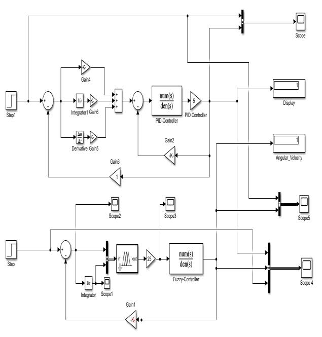
This section of the paper presents a rule base intelligent controller known as Fuzzy logic controller which is designed using the FIS editor. Fuzzy logic tool box is utilized to construct a rule base with the help of some linguistic rules framed in accordance with the requirements.Thedifferent variablestoframea rulebase forgettingthedesiredoutputareenlistedintable2.Here a twoinput andoneoutput controllerisdesignedandthe variousmembershipfunctionsandfuzzyrulesareframed. The two inputs are error and sum_error and output is speed. Figure 3 shows the fuzzy logic interface for different rules and three dimensional view of different ruleswhichareframedbyusingthetoolbox.
Table 2 Rulebasetableforinputsandoutput Error/Sum_error CEN CEZ CEP EN N N Z
International Research Journal of Engineering and Technology (IRJET) e-ISSN:2395-0056
Volume: 11 Issue: 03 | Mar 2024 www.irjet.net p-ISSN:2395-0072
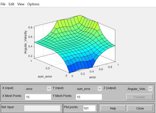
Figure 3: FuzzyControllerinterfaceusing“FuzzyLogic Designer”inMATLAB:(a)Fuzzylogicinterfaceforrules; (b)ThreedimensionalviewofInputsandoutputforspeed control
PSO or Particle Swarm Optimization is a metaheuristic optimization technique that is often used to optimize PID controller parameters. PSO works by simulating the characteristics of a union of particles moving through a search space and searching for the optimal parameter valuesthatminimizeagivencostfunction.ByusingPSOto optimize the PID controller parameters, it is possible to findthevaluesthatwillprovidethebestperformancefora givenDCmotorspeedregulationapplication.
The PSO (Particle Swarm Optimization) algorithm is a stochastic optimization algorithm that is based on the motionofbirdflocksorfishschools.Itwasfirstproposed byKennedyandEberhart[10]andhassincebeenusedin many optimization problems, including the optimization ofPIDcontrollertoregulate thespeedofa DCmotor.The PSO technique starts by initializing a group of members,
where each individual member represents a local best solution to the optimization problem. Each member has a position and a velocity in the search domain, and the position gives the current solution to the optimization problem. The velocity represents the direction and magnitudeofthemember'smovementinthesearchspace. During each iteration of the algorithm, the fitness of each particle is evaluated based on a fitness function that measures how well the particle solves the optimization problem. In the case of optimizing the PID controller parameters for the motor speed control, the fitness function measures the efficiency of the PID controller in the form of accuracy, stability, and robustness . After evaluating the fitness of each member, the member with the best fitness, is identified as the "global best" particle. Theglobal bestlocationisthenupdatedtotheposition of the global best particle. The velocity and position of each particlearethenchangedusingthefollowingequations:
whereV_ijisthevelocityofmemberiindimensionj,w is theinertiaweight,c1 andc2 areaccelerationcoefficients,r1 andr2 arerandomnumbers,Pbest_ijisthebestpositionof memberiindimensionj,Gbest_jistheglobalbestposition indimensionj,andX_ijisthecurrentpositionofparticlei in dimension j. The PSO algorithm continues for a certain number of iterations or until a stopping criterion is fulfilled.The working of PSO-Optimized PID controller is executedbythefollowingsteps:
Step 1. The parameters of the technique like maximum number of iterations (itermax), number of generations, swarm size, minimum inertia weight (wmin), maximum inertiaweight(wmax).
Step 2. Theinertiaweightiscalculatedas: w = wmax –(wmax – wmin)/itermax
Step 3. The values of Kp, Kd and Ki are initialized with a certainoptimumrange.
Step 4. The fitness of each agent is evaluated based on Integralofsquareerror(ISE)parameterandisgivenas:
ISE=∫
Step 5. The personal-best, Pbest and global-best, Gbest of particles are evaluated based on fitness function counted instep4.
Step 6. The velocity and position of the particles are updatedaccordingtoequationsgivenin13and14.
International Research Journal of Engineering and Technology (IRJET) e-ISSN:2395-0056
Volume: 11 Issue: 03 | Mar 2024 www.irjet.net p-ISSN:2395-0072
Step 7. The steps from 2 to 6 are repeated until a terminationcriterionismet.
The performance of the DC motor speed control can be evaluated using several performance metrics. These metrics are used to assess the accuracy, stability, and robustness of the controller, as well as its potential to respondtovariousoperatingconditionsanddisturbances. The following are some of the common performance metricsusedtoevaluatethePSOoptimizedPIDcontroller formotorspeedcontrol
(a) Steady-stateerror:Thismetricmeasurethedifference betweenthedesiredandtheactualspeedofthemotor after the controller has reached a steady-state condition. A smaller steady-state error indicates betterperformance.
(b) Rise time: This metric measure the time it takes for themotortoreach90%ofthedesiredspeedfromthe initial state. A shorter rise time indicates faster responseandbetterperformance.
(c) Settlingtime:Thismetricmeasurethetimeittakesfor the motor to settle to within a specified range of the desired speed after reaching the steady-state condition. A shorter settling time indicates better performance.
(d) Overshoot: This metric measures the extent to which the motor speed overshoots the desired speed before settling to the steady-state condition. A smaller overshootindicatesbetterperformance.
(e) Robustness: This metric measures the ability of the controller to maintain stable and accurate speed control in the presence of disturbances or variations in the system parameters. A more robust controller can handle a wider range of operating conditions and disturbances.
Theseperformancemetricscanbeutilizedtocomparethe working efficiency of different controllers or to optimize thePIDcontrollerparametersusingthePSOalgorithm.By evaluating the performance of the different controllers using these metrics, researchers can assess the effectiveness of the different controllers and PSO optimization technique and its ability to improve the performanceoftheDCmotorspeedcharacteristics.
The experimental or simulation results of the different controllers and PSO optimized PID controller can be representedinvariousforms,includinggraphs,tables,and charts. These results can be used to demonstrate the effectiveness of the different controllers and PSO algorithminoptimizingthePIDcontrollerparametersand improving the performance of the motor speed control system.Astepresponsegraphcanbeusedtoillustratethe performance of the different controllers and PSO
optimized PID controller under a step response in the desired speed. The step response graph shows how the actualspeedofthemotorrespondstoastepchangeinthe desired speed. The graph shows the actual speed of the motor as it responds to the change, and can highlight the steady-state error, rise time, settling time, and peak overshootofthecontroller.
ThePSOalgorithmisaprolificoptimizationtechniquethat can be used to optimize the PID controller parameters used in different applications. The algorithm works by simulating the behavior of particles moving through a search space and searching for the optimal parameter values that minimize a given fitness function. The PSO algorithm has numerous advantages over other optimization types. It is easy to implement, computationally efficient, and can handle non-linear and multi-objective optimization problems. Additionally, PSO can avoid getting stuck in local optima, which can be a common problem in gradient-based optimization techniques. In the context of motor speed regulation, the PSO algorithm can be used to optimize the PID controller parameters to achieve better performance compared to manual tuning or other optimization techniques. The PSO optimized PID controller can provide accurate and stable control of the motor speed, as well as robustness to external disturbances or variations in the system parameters.
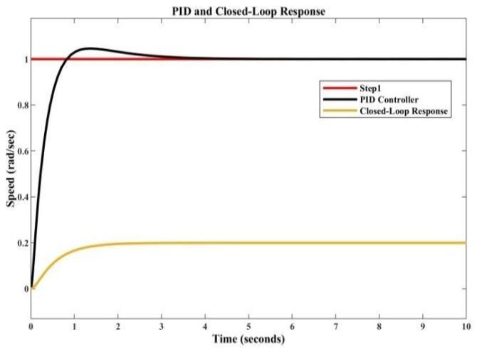
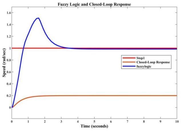
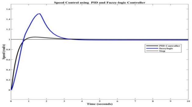
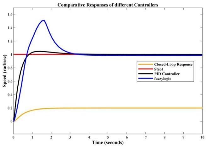
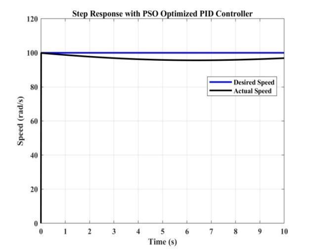
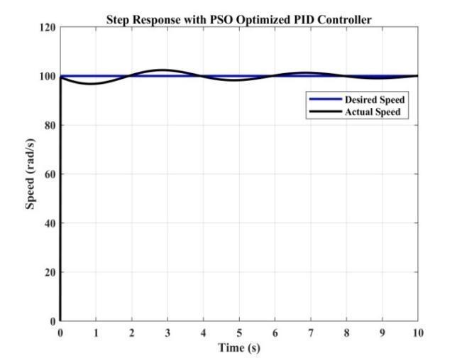
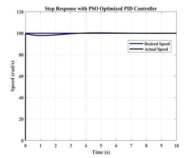
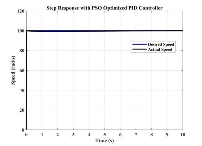
PID controller is one of the versatile controller used to control the speed of motors. Without using the controller the open loop and closed loop responses have totally undesirable transient and steady-state characteristics. By usingthePIcontrollerthesteady-stateerrorisminimized but there is considerable error in other parameters. PID and Fuzzy logic controllers makes the desired response smooth and reduces all the drawbacks which are present in P and PI controller.The complete analysis shows that the PSO optimized PID controller has better performance ascomparedtoothercontrollerswhichisclearlydepicted from the given responses. From the design constraint pointofviewasweincreasethevalueofKp theoscillatory response of the system increases and if it is decreased settlingtimelimitwillnotbeinadesignedrange.Figure4 shows the open-loop, closed-loop, PID and Fuzzy-logic controller responses of DC motor. Figure 5 shows the comparative step responses of different configurations using PID and Closed-loop response, Fuzzy-logic and Closed-loop response, PID and Fuzzy-logic response, and PID, Fuzzy-logic and Closed-loop responses. Figure 6 shows the step responses of DC motor using PSOOptimized PID controller. From all these characteristics it is clear that PID and PSO-Optimized PID controller shows better response. Overall the use of PSO-Optimized PID controller shows better responses with good tracking accuracy, steady state error and better rise time and settlingtimewhich ishighlightedintable3.
International Research Journal of Engineering and Technology (IRJET) e-ISSN:2395-0056
Volume: 11 Issue: 03 | Mar 2024 www.irjet.net p-ISSN:2395-0072
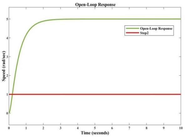
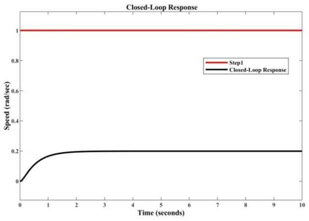
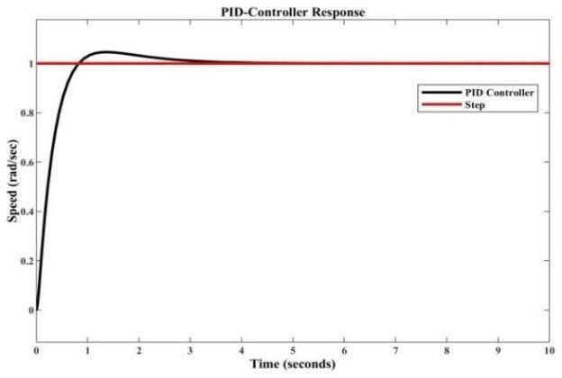
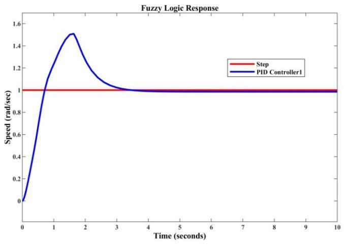
Figure 4: Stepresponseofdifferentconfigurations:(a) Open-loopresponse;(b)Closed-loopresponse;(c)PID controllerresponse;(d)Fuzzy-logicresponse
(b) (c) (d)
Figure 5: Comparativestepresponsesofdifferent configurations:(a)PIDandClosed-loopresponse;(b) Fuzzy-logicandClosed-loopresponse;(c)PIDandFuzzylogicresponse;(d)PID,Fuzzy-logicandClosed-loop response.
© 2024, IRJET | Impact Factor value: 8.226 | ISO 9001:2008 Certified Journal | Page925
Volume: 11 Issue: 03 | Mar 2024 www.irjet.net
2395-0072
Figure 6: StepresponsebyusingPSO-OptimizedPID controllerwithc1=c2 =1.5:(a)Responseforswarmsize 20andmaximumiteration50,w=0.8,r1=r2=0.8;(b) Responseforswarmsize30andmaximumiteration80,w =0.8,r1=r2=0.7;(c)Responseforswarmsize50and maximumiteration100,w=0.8,r1=r2=0.6;(d)Response forswarmsize80andmaximumiteration100,w=0.8, r1=r2=0.9.
Table 3 ComparativeAnalysisofdifferentControllers
Controller
The kinematical model of the motor is simplified and modified using different controllers like PID, Fuzzy and PSO-Optimized PID controller. To improve the working efficiency,differentparametersofthecontrollerarevaried and an optimum performance is found out. Open loop system and closed loop system give totally undesired responses with large steady-state error, delay time and settling time. Thesecharacteristicsare modifiedusingthe PID, Fuzzy logic and PSO-Optimized PID controller. Further fuzzy logic controller is added individually and alsowithPIDcontrollerfortherelativeperformance.After comparing the responses as shown in figures above, PSOOptimized PID controller gave better performance in terms of robustness, tracking accuracy, stability, undesirableovershootsanddelaytimesascomparedtoall other controllers. Future work involves Model Predictive Control (MPC), Artificial Neural network (ANN) and GAInternational Research Journal of Engineering and Technology (IRJET)
International Research Journal of Engineering and Technology (IRJET) e-ISSN:2395-0056
Volume: 11 Issue: 03 | Mar 2024 www.irjet.net p-ISSN:2395-0072
Optimized PID controller approaches. From the robustnesspointofview,wehavetoincludemorenumber of plots, observations and tables for the better understanding and comparison of different strategies. Overall, the PSO optimized PID controller for DC motor speedcontrolisapromisingresearchareathatcanleadto improvedperformanceandefficiencyinvariousindustrial androboticapplications.
[1] Montesano, L. Díaz, M. Bhaskar, S. Minguez, J. “Towards an intelligent wheelchair system for users with cerebral palsy”. IEEE Transactions on Neural Systems and Rehabilitation,vol. 18, pp. 193–202, 2010.
[2] Huma khan, Shahida Khatoon and Prena Gaur, “Comparision of various controller design for the speed control of DC motors used in two wheeled mobile robots”. International Journal of Information Technology,vol.13,pp.713-720,2021.
[3] Umesh Kumar Bansal and Rakesh Narvey, “Speed Control of DC Motor Using Fuzzy PID Controller”. Advance in Electronic and Electric Engineering, vol.3, no.9,pp.1209-1220,2013.
[4] Philip A. Adewuyi, “ DC Motor Speed Control: A Case between PID Controller and Fuzzy Logic Controller”. InternationalJournalofMultidisciplinarysciencesand engineering,vol.4,no.4,pp.36-40,2013.
[5] Rekha Kushwah and SulochanaWaadhwani, “Speed Control of Separately Excited DC motor using Fuzzy LogicController”.InternationalJournalofEngineering Trends and Technology (IJETT), vol. 4,pp. 25182523,2013.
[6] K.PremkumarandB.V.Manikandan,“AdaptiveNeuroFuzzy Inference System based speed controller for brushless DC motor”. Neurocomputing, vol. 138,pp. 260-270,2014.
[7] Ruey-Jing Lian, “Intelligent Controller for Robotic Motion Control”.IEEE Transactions on Industrial Electronics,vol.58,pp.5220-5230,2011.
[8] S.Ushakumari, R. Sankaran and P.S Chandramohanan Nair, “Adaptive Neuro-Fuzzy Controller for Improved Performance of a Permanent Magnet Brushless DC Motor”. IEEE International Fuzzy Systems Conference,pp.493-496,2001.
[9] Pragasen Pillay and Ramu Krishnan, “Modeling,Simulation and Analysis of PermanentMagnet MotorDrives”.IEEE TransactionsonIndustry Applications,vol.25,pp.274-279,1989.
[10] James Kennedy and Russell Eberhart “Particle Swarm Optimization”. Proceedings of ICNN’95-International conference on neural networks 4, pp. 1942-1948, 1995.
[11] DongshuWang,DapeiTanandLeiLiu“Particleswarm optimizationalgorithm:anoverview”.SoftComputing, Springer,pp.387-408,2018.
[12] Ruchi V. Jain, M.V. Aware and A.S. Junghare, “Tuning of Fractional Order PID Controller Using Particle Swarm Optimization Technique for DC Motor Speed Control”. IEEE International Conference on Power Electronics, Intelligent Control and Energy Systems (ICPEICES-2016),pp.1-4,2016.
[13] K. Premkumar and B.V.Manikandan, “Stability and Performance Analysis of ANFIS Tuned PID Based Speed Controller for Brushless DC Motor”. Current SignalTransductionTherapy,vol.13,pp.19-30,2018.
[14] M.A.Jabbar,Hla Nu Phyu and Chao Bi, “Modeling and Numerical Simulation of a Brushless PermanentMagnet DC Motor in Dynamic Conditions by TimeStepping Technique”. IEEE Transactions on Industry Applications,vol.40,pp.763-770,2004.
[15] Ang, K.H. And Chong, G.C.Y. And Li, Y. ,”PID Control System analysis,design and technology” in IEEE Transactions onControl Systems Technology,pp.559576,2005.
[16] SalmiahAhmad,Nazmul H.Siddique and M. Osman Tokhi, “A Modular Fuzzy Control Approach for TwoWheeled Wheelchair”. Journal of Intelligent Robot Systems,vol.64,pp.401-426,2011.
[17] Manoj Dhondiram Patil,K.Vadirajacharya and Swapnil W.Khubalkar,“DesignandTuningofDigitalFractionalOrder PID Controller for Permanent Magnet DC Motor”. IETE Journal of Research,Taylor and Francis,vol.20,pp.1-11,2021.
[18] Do KhacTiep, Kinam Lee, Dae-Yeong Im and YoungJae Ryoo, “Design of Fuzzy-PID Controller for Path Tracking of Mobile Robot with Differential Drive’. International Journal of Fuzzy Logic and Intelligent Systems,vol.18,pp.220-228,2018.