
International Research Journal of Engineering and Technology (IRJET) e-ISSN:2395-0056
Volume:11Issue:03| Mar2024 www.irjet.net p-ISSN:2395-0072
International Research Journal of Engineering and Technology (IRJET) e-ISSN:2395-0056
Volume:11Issue:03| Mar2024 www.irjet.net p-ISSN:2395-0072
Archana R1 , L Govindaraju2
1Post graduate student, Dept. of civil engineering, UVCE Bangalore University, Bengaluru
2Professor, Dept. of Civil Engineering, UVCE Bangalore University, Bengaluru-560056
Abstract - Deep excavation is a common practice of construction in denselypopulatedareas,uncertaintyproblems can arise due to the significant settlement at the ground surface and large movements at the facing of the excavation walls. Stabilizing these excavations can be achieved by the most popular methods such as micropile and nailing system. This method has also been widely used to stabilize natural slopes and earth retaining structures. In the present study, numerical modelling and the analysis of an 8m deep excavation supported with different earth retaining systems has been carried out by adopting finite element-based software PLAXIS 2D. A parametric study is conducted using a double row micropile system and a composite system using micropile and nail system. The behavior of the soil body, the forces generated in the micropile, nails, and global safety factors are compared for eachcase in both static anddynamic conditions. In the case of a double row micropile, the soil body collapse during the final excavation indicating instability condition. To overcome this problem, a composite system has been adopted The influence ofbuilding load on the stabilityof deep excavation has also been investigated in the present study. The building is placed at different offsets from the excavation line and the behavior of the soil body is compared for all the cases. It is found that when the building is at the edge of the excavation line without any offset, the maximum displacement and bending moment are observed and vice versa.
Key Words: Deepexcavation,Compositesystem,Double rowmicropile,Groutednail,PLAXIS2D
1.INTRODUCTION
Duetorapidurbandevelopmentsandgrowingpopulationin themajorcitiesaroundtheworld,theneedforunderground space has increased. Therefore, deep excavations for development of underground space, such as subway transportation networks, tall buildings basements, underground car parks, and shopping centres have been widely used [2]. However, due to scarcity of land, major developments are increasingly being carried out in peripheralareasofthecity.Thissituationpresentedunique challenges and opportunities for innovative design as the selling price is not enough for conventional basement excavation technique (e.g. Diaphragm wall) to be economically feasible. However, with larger development
area,someflexibilityinbasementlayoutanddesignallow techniquessuchassoilnailandmicropiletobe employed even for deep excavation with basement of greater depth. Now a days in Earth retention or Deep excavations stabilizationaregenerallyfollowedbymanymethodshere wefollowedMicropileandSoilnailingtechnique.
InthispresentstudyaCompositesystemusingdouble rowmicropilewithandwithoutnailingsystemisanalysed for a deep excavation of 8m using finite element package PLAXIS2D.ThesystemconsistoftheDoublerowmicropile withgroutednailingtechniqueisadoptedinthewaysuch that the system retains the soil and prevent the soil from cave-inorcollapse.
Amicropileisasmall-diameter(typicallylessthan300mm), drilled and grouted replacement pile that is typically reinforced.Generally,micropilesareapplicablewhenthere are problems with using conventional deep foundation systems. These problem conditions include: obstructions, adjacentstructures,limitedaccessjobsites,andothershaky areaslikecaves,sinkholes,undergroundrivers.Forexample, micropilesarecommonlythepreferredfoundationchoicein the challenging areas that feature nearby buildings and difficultaccess[3].Installationtechniquesvarydepending on the load bearing specifications of the project. The selectionoftheinstallationtechniquedependslargelyonsoil conditionsandloadtransferrequirements.
Generally,micropileconsistsoftwogeneralapplications, a) Structuralsupport
b) In-situreinforcement
Soil nail walls are particularly well suited to excavation applicationsforgroundconditionsthatrequireverticalor near-vertical cuts. They have been used successfully in highway cuts; end slope removal under existing bridge abutments during underpass widening; for the repair, stabilization, and reconstruction of existing retaining structures; and tunnel portals [13]. Soil nailing is an economicaltechniqueusedtostabilizeexistingslopesandto construct retaining walls from top down. The soil reinforcementprocessusessteeltendonswhicharedrilled
International Research Journal of Engineering and Technology (IRJET) e-ISSN:2395-0056
Volume:11Issue:03| Mar2024 www.irjet.net p-ISSN:2395-0072
andgroutedintothesoiltocreateacompositemasssimilar to a gravity wall. Soil nails are usually installed at an inclination of 10 to 20 degrees with horizontal and are primarilysubjectedtotensilestress.
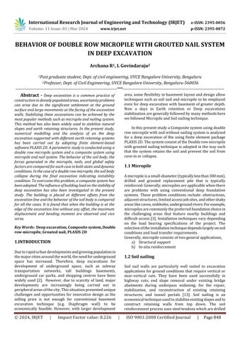
8m vertical deep excavation in a homogeneous soil strata supportedbyusingdoublerowmicropilewithandwithout groutednailingtechniques.Takingsurchargeofuniformly distributedload50kPa(buildingload)alongtheexcavation line.
Table-1: Soilproperties
Table-3: PropertiesofGroutednailforDoublerow micropile(FHWA-NHI-14-007)
Table-4: PropertiesofCappingbeamandBasement (PLAXISmanual)
3
Table-5: PropertiesofRestofbuilding(PLAXISmanual)
Table-2: PropertiesofMicropileforDoublerow micropile(FHWA-SA-97-070)
Poisson’s ratio v 0
Thedeepexcavationisanalyzedforvariouscasesbyvarying the parameters of the Micropile and soil nailing, the parameters for which the analysis is performed are listed below.
a] PropertiesofMicropile.
b] Length,spacingandpropertiesofsoilnailing.
c] Positionofbuildingsurchargefromexcavationline.
d] Staticanddynamicanalysis.
PLAXIS version 23 is used for the simulation of 8m deep vertical cut in soil using staged construction of composite systemandanalyzingtheresponseofmicropileandnailing, understaticandseismiccondition.Numericalmodellingis carriedouttakingtheplanestrainstateofstresses.The15nodetriangularelementwithfinermeshdensityareusedfor thefiniteelementdiscretization.Thein-situsoilissimulated
International Research Journal of Engineering and Technology (IRJET) e-ISSN:2395-0056
Volume:11Issue:03| Mar2024 www.irjet.net p-ISSN:2395-0072
asMohr-coulomb(MC)materialforthestaticanddynamic analysis.Figure3showsthedynamicanalysis,strongmotion record of upland earthquake respectively is used. Nailing and micropile are simulated as the linear elastic material. Plate element is used to model the micropile and nailing system. The analysis is performed for a 8m deep vertical excavationsupportedbycompositesystemusingdoublerow micropilewithandwithoutnailing,consideringasurcharge loadof50kPa(buildingload)startingfromtheexcavation line.Thedeepexcavationisperformedasstagedexcavation, Excavationsequencesaresimulatedasthestagedexcavation with2-mexcavationliftineachstage.Theanalysisiscarried outinthesequenceindicatedbelow.
1.Startinganewproject.
2.Creatingsoilstratigraphyusingthegeometrylinefeature.
3.Creatingandassigningofmaterialdatasetsforsoilstrata (MCmodel).
4.Assigningthedynamiclineloadtomodel.
5. Creating and assigning of properties for double row micropile(plateelement).
6. Creating and assigning of properties for grouted nails (plateelement).
7 Assigningadistributedloadtomodelthesurchargeload.
8.Meshgeneration.
9 Calculation of staged excavation
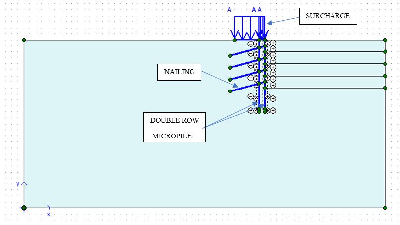
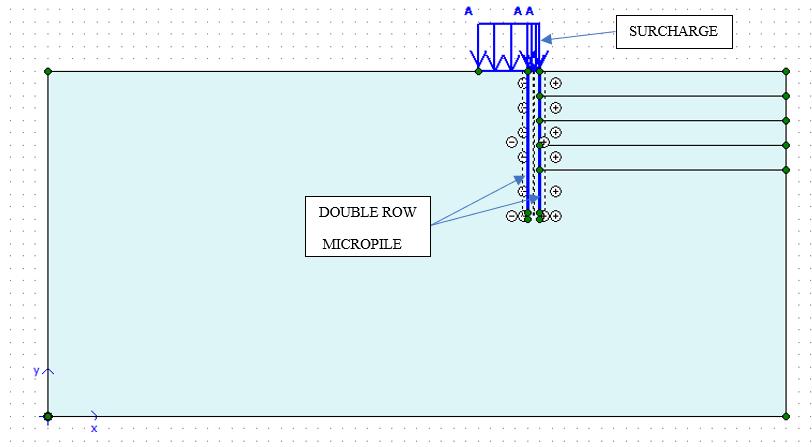
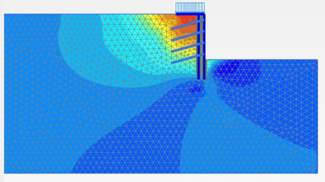
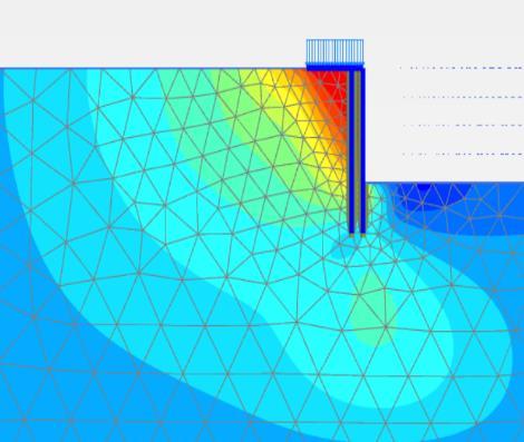
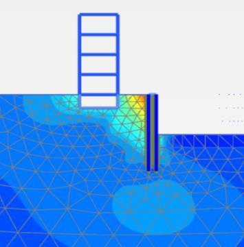
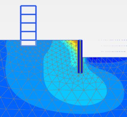
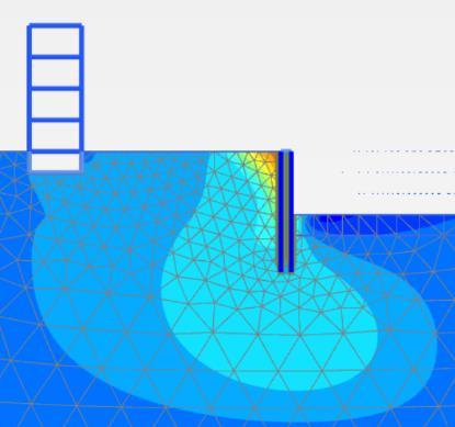
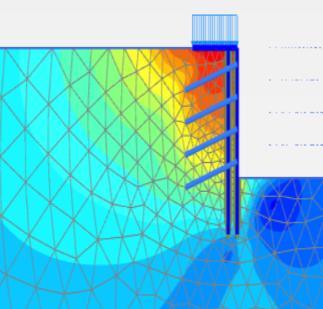
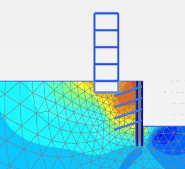
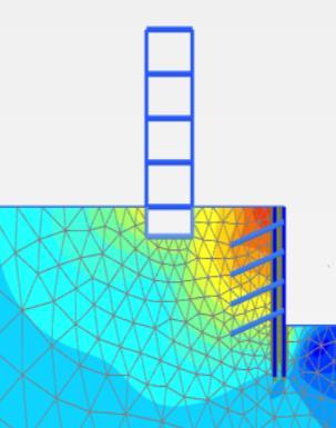
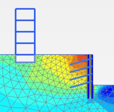
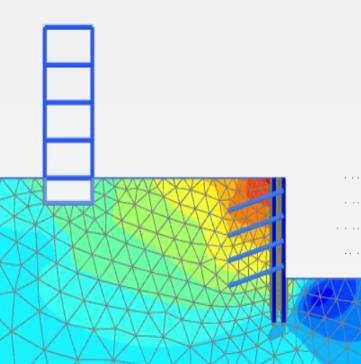
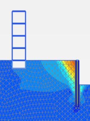
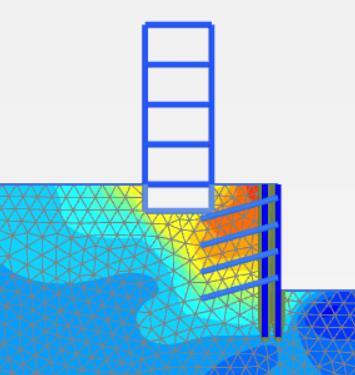
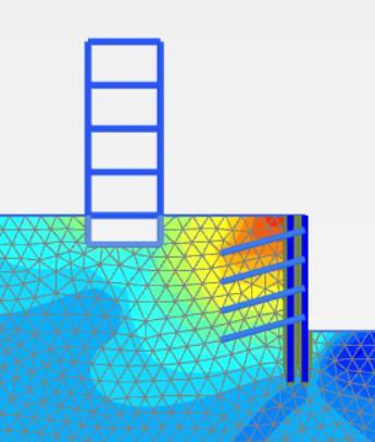
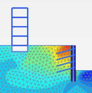
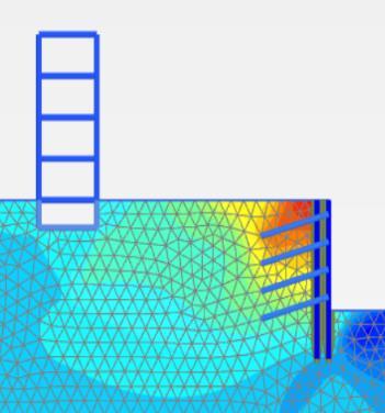
Figure1showstypicalmodelofthehomogeneoussoilstrata and the support system provided for the proposed excavation,byadoptingdoublerowmicropilewithgrouted nailingsystemandfigure2showsthetypicalmodelofthe double row micropile without nailing system is prepared usingnumericalmodelingtoolPLAXIS2D.
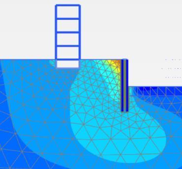
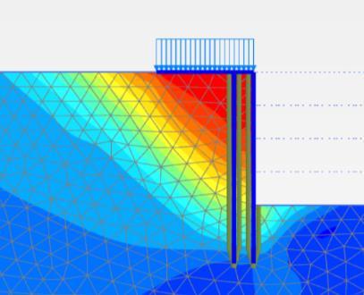
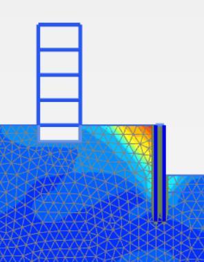
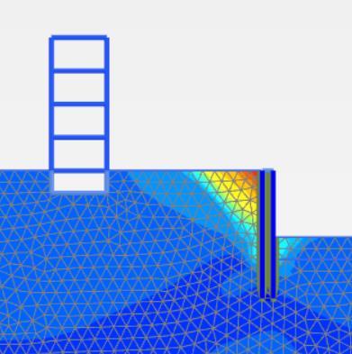
Figure3and4showsthedeformedmesh,howthesoilbody deformsaftertheexcavationof8mdeepismadeusingthe double row micropile with grouted nails. The double row micropile with grouted nails deflects due to the earth pressureandthebuildingload,bottomheaveisobservedat thefinalexcavationlevel.
2.3
In this present study a Composite system using micropile andnailingsystemisanalysedforadeepexcavationof8m usingfiniteelementpackagePLAXIS2D.Thesystemconsists of the Double row micropile with and without nailing techniqueisadoptedinthewaysuchthatthesystemretains the soil and prevent the soil from cave-in or collapse. Micropileandnailingsystemisanalysedfordifferentcases, varyingtheconfigurationofthesystemsuchasthedouble rowmicropilewithorwithoutNailsandalteringthelength andspacingofnails.Thedifferentcaseswerealsoanalysed byvaryingthebuildingloadlocation.Theseallcaseswere analysed by both Static and Dynamic conditions. In Static conditionstheforcesactingonthesystemsuchasthelateral
International Research Journal of Engineering and Technology (IRJET) e-ISSN:2395-0056
Volume:11Issue:03| Mar2024 www.irjet.net p-ISSN:2395-0072
earthpressureiscalculatedandthesystemismadesuchthat is resist all the forces acting on the system. In dynamic conditiontheforcesgeneratedduetothedynamicloading werecalculatedandthesystemismadesuchthatitresists the forces effectively without any failure. The various parametersthatwerevariedduringanalysisareasfollows
1.Doublerowmicropilewithorwithoutnails.
2.Buildingloadlocation.
3.TypeofAnalysis. Staticanalysis
Instaticanalysistheloadswhichareactingonthesystemis constantwithrespecttotime.So,ateveryinstanceoftime the magnitude of the forces acting on the micropile is constant.Toperformstaticanalysisinfiniteelementanalysis programme the geometry of the problem is defined, the double row micropile with and without grouted nailing systemismodelledandtheanalysisiscarriedoutinstage manner.
1. Doublerowmicropile
Inthiscase,theuseofadoublerowmicropilewasnecessary because the various cases were done with a single row micropile, butthesoil wasnotstrongenough tocarry the load. The systems are designed based on the FHWA micropiledesignandconstruction.Micro-pilesintheformof steel pipesof300mmdiawith16mmthickness,spacedat 50cm and 11.5m length are considered. Horizontal component of shear resistance provides resistance for induced shear forces due to excavating and loading. In addition6rodsof32mmdiameterofsteelrodsareprovided, intheannularspaceofmicropiletoprovideadditionalshear resistanceandcanbepositionedinthecentralspaceofthe pile.Thespaceinthepileandbetweenthesteelrodscanbe filledupwithgrouting.Andtheanalysishasbeencarriedout fordifferentoffsetofbuildingfromthelineofexcavation.
a)Surchargeloadatexcavationline
(a) (b) (c)
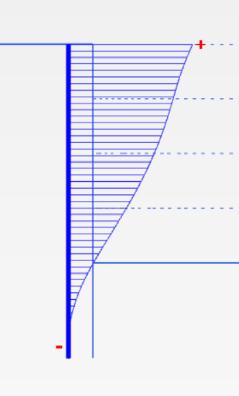
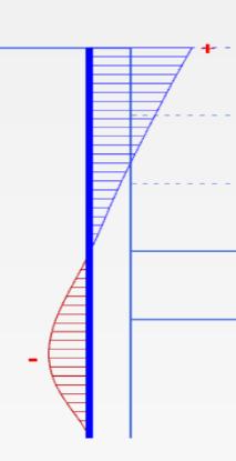
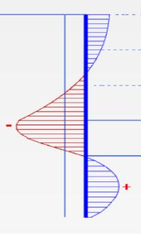
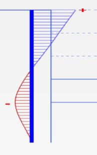
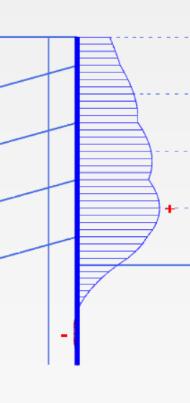
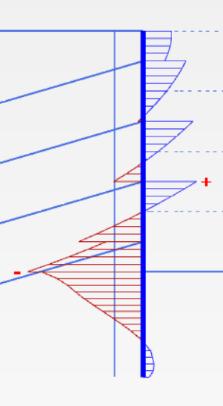
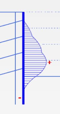
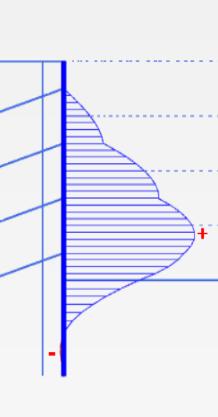
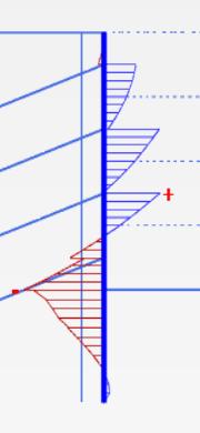
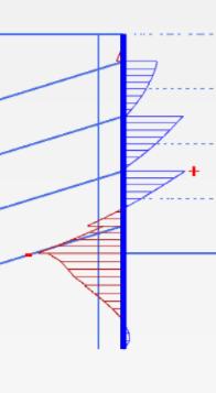
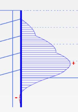
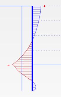
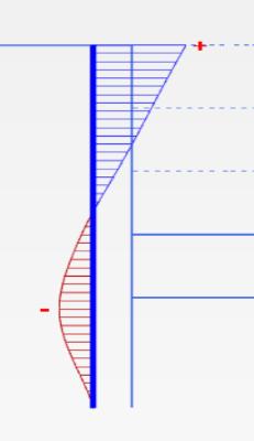
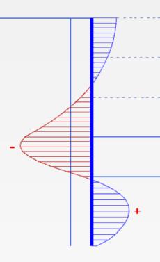
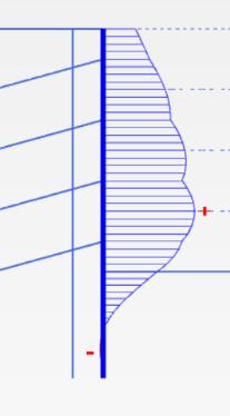
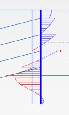
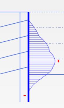
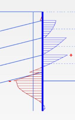
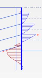
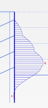
Fig-5: (a)Bendingmomentdiagram(backpile)(b)Shear forcediagram(frontpile)(c)Horizontaldisplacement
Itisseenfromthefigure5thatthesystemissafe,becauseof thecappingbeamisprovidedatthetopitwillactlikeaheld backsystemofferingfixityatthetop.Fromthefigure6(c)it
showsthatthehorizontaldisplacementismaximumatthe topofthewallandisfoundtobe23.76mm(atthestageof excavation4).
b) Building load is located at 5m distance from excavationline
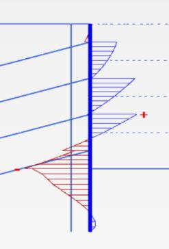
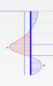
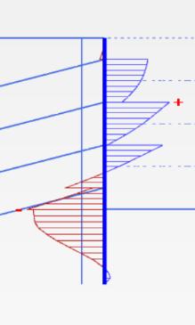
(a) (b) (c)
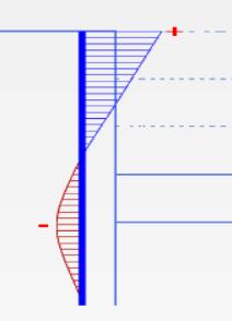
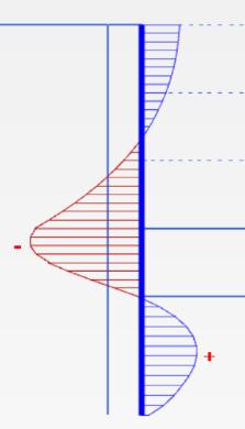
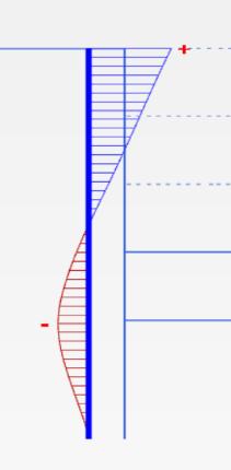
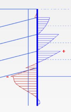
Fig-6: (a)Bendingmomentdiagram(backpile)(b)Shear forcediagram(frontpile)(c)Horizontaldisplacement
c) Building load is located at 10m distance from excavationline
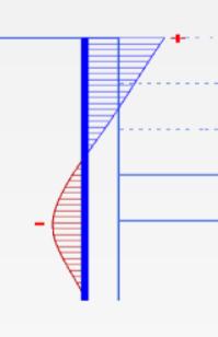
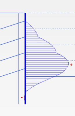
(a) (b) (c)
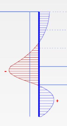
Fig-7: (a)Bendingmomentdiagram(backpile)(b)Shear forcediagram(frontpile)(c)Horizontaldisplacement
d) Building load is located at 15m distance from excavationline
(a) (b) (c)
Fig-8: (a)Bendingmomentdiagram(backpile)(b)Shear forcediagram(frontpile)(c)Horizontaldisplacement
International Research Journal of Engineering and Technology (IRJET)
Volume:11Issue:03| Mar2024 www.irjet.net
e) Building load is located at 20m distance from excavationline
(a) (b) (c)
Fig-9: (a)Bendingmomentdiagram(backpile) (b)Shearforcediagram(frontpile)(c)Horizontal displacement
Itisseenfromthefigure6to9thatthesystemfailsatthe excavationof8m.Thereasonforthefailureisthesoilbody collapse (at the stage of excavation 4). It shows that the horizontal displacement of the double row micropile is maximum at the top of the wall and that the system so providedfortheexcavationof8misnotsufficienttoresist theexternalloads,andthesystemhastoberedefined.
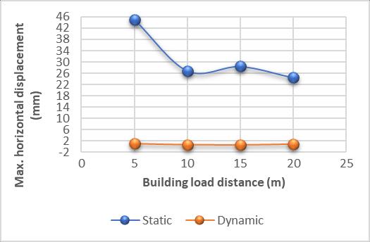
Chart 1 shows that the building load distance from excavationlineandthecorrespondingmaximumhorizontal displacementinthewallafterthefinalstageofexcavation. From the graph we can see that the displacement is not maximum when the Surcharge load is placed at the excavation line but it is maximum when the surcharge is placedat5m from the excavationline in the caseof static analysis and is maximum when the load is placed at excavation line in the case of dynamic analysis. When the surchargeplacedfurtherawayfromtheexcavationlinethe displacementkeepsdecreasingandalmostbecomeconstant (i.e.,at8m).
p-ISSN:2395-0072
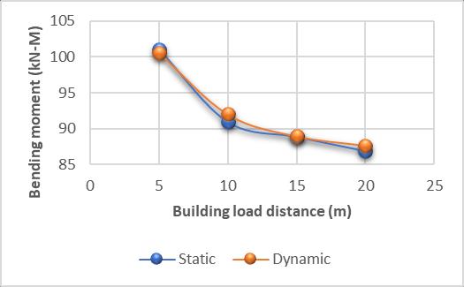
Chart – 2: BuildingloaddistancevsMaximumBending moment(Frontpile)
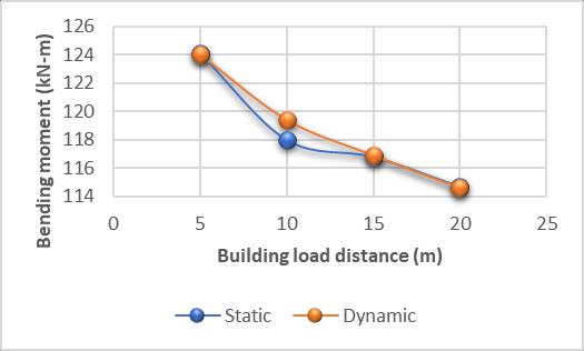
Chart – 3: BuildingloaddistancevsMaximumBending moment(Backpile)
Chart 2 and 3 shows that the building load distance from excavation line and the corresponding maximum bending momentinthewallafterthefinalstageofexcavation.From thegraphwecanseethatthebendingmomentismaximum whentheSurchargeloadisplacedattheexcavationline(i.e., at0m)anditwillgoesondecreasingasthesurchargeloadis placedawayfromtheexcavationline(forstaticanddynamic condition).Aswekeeponmovingthesurchargeawayfrom the excavation line the variation of bending moment will almostbecomeconstant(i.e.,at20m).Thebendingmoment inthebackpileismaximumwhencomparedtofrontpilein caseofdoublerowmicropile.
International Research Journal of Engineering and Technology (IRJET) e-ISSN:2395-0056
Volume:11Issue:03| Mar2024 www.irjet.net p-ISSN:2395-0072
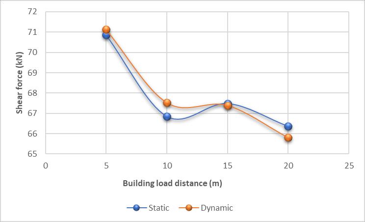
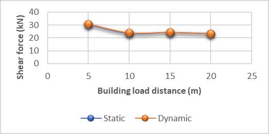
Chart 4 and 5 shows that the building load distance from excavationlineandthecorrespondingMaximumshearforce inthewallafterthefinalstageofexcavation.Fromthegraph we can see that the shear force is maximum when the Surchargeloadisplacedattheexcavationline(i.e.,at0m) anditwillgoesondecreasingasthesurchargeloadisplaced awayfromtheexcavationline(forbothstaticanddynamic condition).Aswekeeponmovingthesurchargeawayfrom theexcavationlinethevariationofshearforcewillalmost become constant (i.e., at 8m). The shear force in the front pile is maximum when compared to back pile in case of doublerowmicropile.
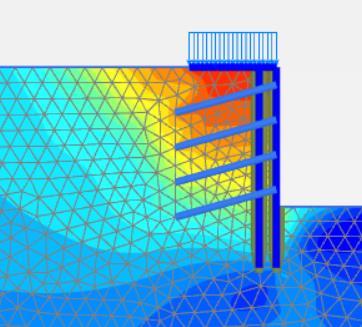
2. Doublerowmicropilewithgroutednail
Doublerowmicropileoptionhasbeentriedandfailedatthe final excavation stage, to overcome this case, adopt compositesystemusingdoublerowmicropilewithnailing and the analysis has been done by inserting 6m nail atan angleof15 inclinationandtheconstructioniscarriedout. Initially2mexcavationiscarriedandfollowedbyinsertion ofnailsatanintervalof2m.ifstabilityisless,thenthenail lengthisincreasedtoachievethefactorofsafetymorethan 1.5. Further another 2 m excavation is carried and the
process is repeated until a depth of 8m. Design of nailing systemdonebyusingFHWAsoilnailreferencemanual.And the analysis has been carried out for different offset of buildingfromthelineofexcavation.
a)Surchargeloadatexcavationline
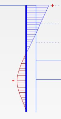
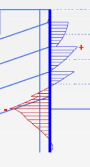
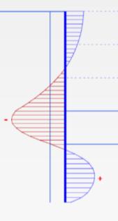
(a) (b) (c)
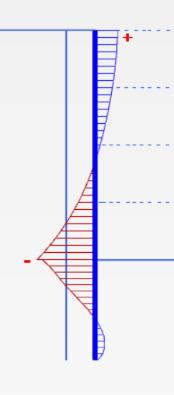
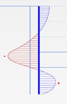
Fig-10: (a)Bendingmomentdiagram(backpile) (b)Shearforcediagram(frontpile)(c)Horizontal displacement
b) Building load is located at 5m distance from excavationline
(a) (b) (c)
Fig-11: (a)Bendingmomentdiagram(backpile) (b)Shearforcediagram(frontpile)(c)Horizontal displacement
c) Building load is located at 10m distance from excavationline
(a) (b) (c)
Fig-12: (a)Bendingmomentdiagram(backpile) (b)Shearforcediagram(frontpile)(c)Horizontal displacement
International Research Journal of Engineering and Technology (IRJET) e-ISSN:2395-0056
Volume:11Issue:03| Mar2024 www.irjet.net
d) Building load is located at 15m distance from excavationline
(a) (b) (c)
Fig-13: (a)Bendingmomentdiagram(backpile)(b) Shearforcediagram(frontpile)(c)Horizontal displacement
e) Building load is located at 20m distance from excavationline
(a) (b) (c)
Fig-14: (a)Bendingmomentdiagram(backpile) (b)Shearforcediagram(frontpile)(c)Horizontal displacement
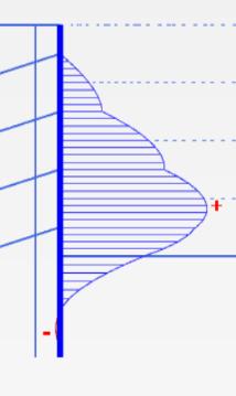
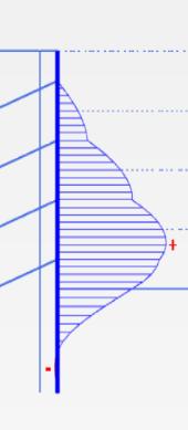
Fromtheabovefigures10to14,itseenthatthehorizontal displacementofthedoublerowmicropileismaximumatthe topofthewall.Fromtheanalysisresultsthatthesystemso providedfortheexcavationof8missufficienttoresistthe externalloads,andthesystemissafe.
p-ISSN:2395-0072
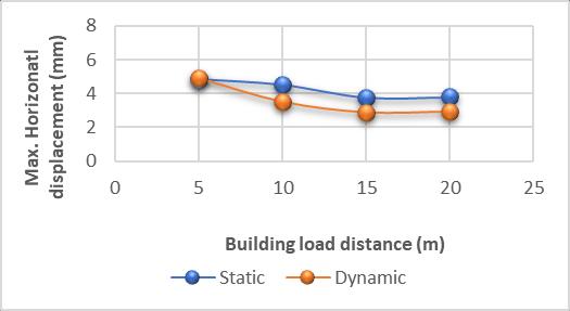
Chart 6 shows that the building load distance from excavationlineandthecorrespondingmaximumhorizontal displacementinthewallafterthefinalstageofexcavation. From the graph we can see that the displacement is not maximumwhenthebuildingloadisplacedattheexcavation linebutitismaximumwhenthebuildingloadisplacedat 5mfromtheexcavationlineinthecaseofdynamicanalysis. When the building load placed further away from the excavation line the displacement keeps decreasing and almostbecomeconstant(i.e.,at8m).
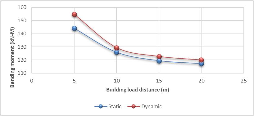
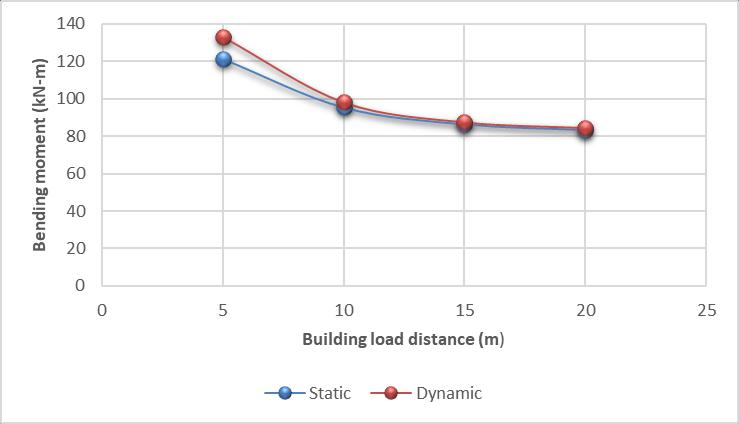
Chart 7 and 8 shows that the building load distance from excavation line and the corresponding maximum bending momentinthewallafterthefinalstageofexcavation.From thegraphwecanseethatthebendingmomentismaximum whenthebuildingloadisplacedattheexcavationline(i.e.,at 0m) and it will goes on decreasing as the building load is placed away from the excavation line (for both static and dynamiccondition).Aswekeeponmovingthebuildingload away from the excavation line the variation of bending moment will almost become constant (i.e., at 8m). The bending moment in the front pile is maximum when comparedtobackpileincaseofdoublerowmicropilewith nailing.
International Research Journal of Engineering and Technology (IRJET)
Volume:11Issue:03| Mar2024 www.irjet.net p-ISSN:2395-0072
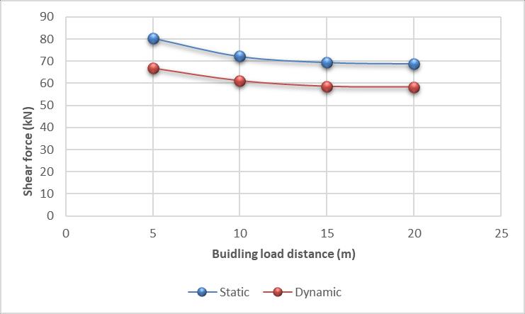

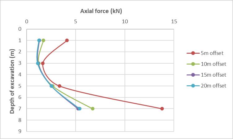
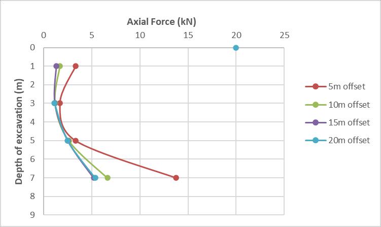
Chart11and12showsthatcomparisonoftheaxialforcein thewall ateverystageof excavation(i.e.,at2mintervals) andforall the casesof buildingload atdifferentlocations from the excavation line (static and dynamic condition). From graph it is seen that the axial force initially will be minimumandgoesonincreasingasthedepthofexcavation increases and it will be maximum at the final stage of excavationi.e.,at8m.Theaxialforcewillbemaximumwhen thesurchargeloadisattheexcavationlinei.e.,at0mandit will be least when the surcharge is at 20m from the excavationline
Chart9and10showsthatthebuildingloaddistancefrom excavationlineandthecorrespondingmaximumshearforce inthewallafterthefinalstageofexcavation.Fromthegraph wecanseethattheshearforceisnotmaximumwhenthe building load is placed at the excavation line but it is maximumwhenthebuildingloadisplacedat5mfromthe excavation line in the case of static analysis. When the building placed further away from the excavation line the shearforcekeepsdecreasingandalmostbecomeconstant (i.e., at 8m). The shear force in the front pile is maximum whencomparedtobackpileincaseofdoublerowmicropile withnailing.
Indynamicanalysistheloadswhichareactingonthesystem arenotconstant buttheyvarywith respectto time. So, at everyinstanceoftimethemagnitudeoftheforcesactingon thecompositesystemis not constant. Dynamicanalysis is studiedtoassesswhetherthestructuralsystemsoprovided issaveinnaturalcalamitiessuchasearthquake.Toperform thedynamicanalysisinfiniteelementanalysisprogramme thegeometryoftheproblemisdefined,andthetime-history analysis is done using the strong ground motion data file whichisavailableinthePLAXIS2Dprogrammefiles.
Thedynamicanalysisisperformedforthosecaseswherethe soilbodyissafeinthestaticanalysis,andforthosecasesin which soil body is collapsing during the excavation stage itself, which is while performing the static analysis the dynamicanalysisisnotperformed.
International Research Journal of Engineering and Technology (IRJET) e-ISSN:2395-0056
Volume:11Issue:03| Mar2024 www.irjet.net p-ISSN:2395-0072
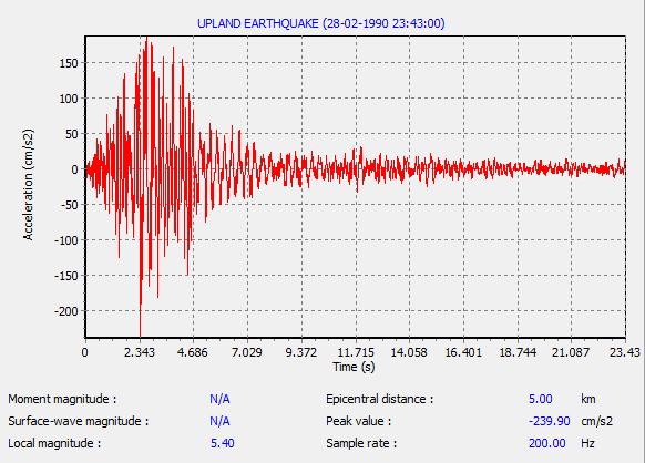
Fig-15:StronggroundmotionrecordofUpland earthquake.
Dynamic analysis is performed using Upland earthquake(occurredduring20th Feb1990at3.44pmin SouthCalifornia)ofpeakaccelerationof0.245g(0.24m/s2).
1. Doublerowmicropile
a) Surchargeloadatexcavationline
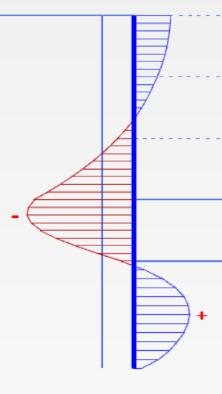
(a) (b) (c)
Fig-16: (a)Bendingmomentdiagram(backpile) (b)Shearforcediagram(frontpile)(c)Horizontal displacement
b) Building load is located at 5m distance from excavationline

(a) (b) (c)
Fig-17: (a)Bendingmomentdiagram(backpile) (b)Shearforcediagram(frontpile)(c)Horizontal displacement
c) Building load is located at 10m distance from excavationline
(a) (b) (c)
Fig-18: (a)Bendingmomentdiagram(backpile) (b)Shearforcediagram(frontpile)(c)Horizontal displacement
d) Building load is located at 15m distance from excavationline
(a) (b) (c)
Fig-19: (a)Bendingmomentdiagram(backpile) (b)Shearforcediagram(frontpile)(c)Horizontal displacement
e) Building load is located at 20m distance from excavationline
(a) (b) (c)
Fig-20: (a)Bendingmomentdiagram(backpile) (b)Shearforcediagram(frontpile)(c)Horizontal displacement
Fromtheanalysisresultsitisseenthatthesystemisnotsafe fordynamicanalysisaswell.Fromthefigure16to20itseen thatwhenthedynamicloadsareappliedthecompletesoil body displaces horizontally along with the double row
International Research Journal of Engineering and Technology (IRJET) e-ISSN:2395-0056
Volume:11Issue:03| Mar2024 www.irjet.net p-ISSN:2395-0072
micropile system. The maximum horizontal displacement recordedisatthestageofexcavation3,andthesystemisnot sufficienttoresisttheexternalload.
a) Surchargeloadatexcavationline
(a) (b) (c)
Fig-21: (a)Bendingmomentdiagram(b)Shearforce diagram(c)Horizontaldisplacement
b) Building load is located at 5m distance from excavationline
(a) (b) (c)
Fig-22: (a)Bendingmomentdiagram(b)Shearforce diagram(c)Horizontaldisplacement
c) Building load is located at 10m distance from excavationline
(a) (b) (c)
Fig-23: (a)Bendingmomentdiagram(b)Shearforce diagram(c)Horizontaldisplacement
d) Building load is located at 15m distance from excavationline
(a) (b) (c)
Fig-24: (a)Bendingmomentdiagram(b)Shearforce diagram(c)Horizontaldisplacement
e) Building load is located at 20m distance from excavationline
(a) (b) (c)
Fig-25: (a)Bendingmomentdiagram(b)Shearforce diagram(c)Horizontaldisplacement
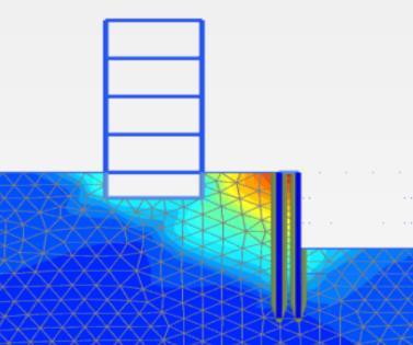
From the Figure 21 to 25 it seen that when the dynamic loads are applied the complete soil body displaces horizontallyalongwiththedoublerowmicropilewithnails. The maximum horizontal displacement is recorded. From theanalysisthatthesystemsoprovidedfortheexcavationof 8missufficienttoresisttheexternalloads,andthesystemis safe.
1. Inadoublerowmicropile,thecappingbeamwillactlike aheldbacksystemofferingfixityatthetop.
2. The minimum bending moments in the micropile are observedinthecaseofthefrontpilewiththemaximum shear force and maximum bending moments are observedinthecaseofabackpilewithminimumshear forceandthesystemfoundtobenotsafetoretaina8m deepexcavation.
3. Due to the enhanced strength of double row micropile with nailing, the maximum horizontal displacement is almostnearerinbothstaticanddynamicconditions.It wasobservedthatthemaximumbendingmomentand shear force occur at the front pile, while the minimum bendingmomentandshearforcetakeplaceattheback pile.
International Research Journal of Engineering and Technology (IRJET) e-ISSN:2395-0056
Volume:11Issue:03| Mar2024 www.irjet.net p-ISSN:2395-0072
4. Theeffectofbuildingloadontheexcavationisstudiedby varyingthebuildingloadoffsetfromtheexcavationline, and it is found that closer the building load to the excavationareagreaterwillbethedisplacementscaused and vice-versa. It was found that, the maximum axial forceisdevelopedatthebottomandminimumatthetop. 5. Indynamiccondition,thedisplacementsandtheforcesin the micropile are more when compared to static condition.
[1]AhmadAlkhdour,AmjadA.Yasin,OleksiiTiutkin(2023), “Rational design solutions for deep excavations using soil nail wall systems”, Mining of mineral deposits Volume 17 (2023), Issue 3, 110-11, https://doi.org/10.33271/mining17.03.110
[2] AliPak,JafarMaleki,NimaAghakhani,MojtabaYousefi (2019), “Numerical investigation of stability of deep excavations supported by soil-nailing method”, Geomechanics and Geoengineering, pp. 1-18. DOI: https://doi.org/10.1080/17486025.2019.1680878
[3] AmitSrivastava, PawanKumar,G.L.ShivakumarBabu (2012), “Stability analysis of 18 m deep excavation using micropiles”,ProceedingsofIndianGeotechnicalConference, Delhi. DOI: https://www.researchgate.net/publication/266602023
[4] André Querelli, Tiago de Jesus Souza, André Augusto Cepeda (2022), “Soil nailing wall with vertical nails to displacement reduction: Brazilian Practice”, licensee UniversidadNacionaldeColombia.RevistaDYNA,89(223), pp. 61-66, ISSN 0012-7353 DOI: https://doi.org/10.15446/dyna.v89n223.97405
[5] Binu Sharma (2009), “A model study of micropiles subjectedtolateralloadingcondition”,IndianGeotechnical Conference,Guntur.pp.371-375.
[6]DeepakHooda,AnupamMittal(2017),“Studyofmicropiles subjected to lateral loading and oblique pull”, International journal of advance research in science and engineering.Volumeno6,issueno1,pp.369-374.
[7] FHWA (1997), Micropile Design and Construction Guidelines Implementation Manual FHWA-SA-97-070 FHWA’s Geotechnical website: http://www.fhwa.dot.gov/bridge/geo.htm
[8] FHWA (2015), “Soil Nail Walls Reference Manual”, AASHTOLRFDBridgeDesignSpecifications,7thEdition, U.S. Department of Transportation Federal Highway Administration,PublicationNo.FHWA-NHI-14-007.
[9] Md. Khaja Moniuddin, P. Manjularani, L. Govindaraju (2016), “Seismic analysis of soil nail performance in deep excavation”,InternationjournalofGeo-engineering,no.7:16, pp.1-10.DOI:10.1186/s40703-016-0030-y
[10] Murthy, B.R. Srinivasa (2010), “Case Studies on Soil Nailed Retaining Systems for Deep Excavations”, Indian GeotechnicalConference,pp.57-62.
[11] Noha El-Shamy, Sayed M. Ahmed, M. A. Abdel-Motaal (2020), “ Seismic Response of Multi-Story Structure Strengthened with Micropiles”, International Journal of EngineeringandAdvancedTechnology(IJEAT)ISSN:22498958 (Online), Volume-9 Issue-6. DOI: 10.35940/ijeat.F1511.089620
[12]PereC.Prat(2016),“Numericalinvestigationintothe failure of a micropile retaining wall”, Computers and Geotechnics 81, pp. 262–273. http://dx.doi.org/10.1016/j.compgeo.2016.08.026
[13]Shivakumarbabu(2009),“Stabilizationofverticalcut usingsoilnailing”,Plaxispractice.pp.6-9.
[14] WenfengLiu, JieMao, HongxingZhao,andGuangbiao Shao(2022),“ExperimentalStudyonDoubleRowMicropiles andAnchorsCompositeRetainingStructureinDeepFillSite” , Hindawi,AdvancesinCivilEngineering,ArticleID5662220, 11pages.https://doi.org/10.1155/2022/5662220